EP0070350B1 - Expanding gate valve with position responsive interlock - Google Patents
Expanding gate valve with position responsive interlock Download PDFInfo
- Publication number
- EP0070350B1 EP0070350B1 EP81890124A EP81890124A EP0070350B1 EP 0070350 B1 EP0070350 B1 EP 0070350B1 EP 81890124 A EP81890124 A EP 81890124A EP 81890124 A EP81890124 A EP 81890124A EP 0070350 B1 EP0070350 B1 EP 0070350B1
- Authority
- EP
- European Patent Office
- Prior art keywords
- gate
- rocker arm
- segment
- assembly
- slot
- Prior art date
- Legal status (The legal status is an assumption and is not a legal conclusion. Google has not performed a legal analysis and makes no representation as to the accuracy of the status listed.)
- Expired
Links
- 230000009471 action Effects 0.000 claims abstract description 3
- 230000004048 modification Effects 0.000 abstract description 2
- 238000012986 modification Methods 0.000 abstract description 2
- 238000006073 displacement reaction Methods 0.000 description 4
- 239000012530 fluid Substances 0.000 description 2
- 238000004519 manufacturing process Methods 0.000 description 2
- 230000004044 response Effects 0.000 description 2
- 238000013459 approach Methods 0.000 description 1
- 230000000712 assembly Effects 0.000 description 1
- 238000000429 assembly Methods 0.000 description 1
- 230000000295 complement effect Effects 0.000 description 1
- 238000012423 maintenance Methods 0.000 description 1
- 230000007246 mechanism Effects 0.000 description 1
- 230000002028 premature Effects 0.000 description 1
- 238000007789 sealing Methods 0.000 description 1
- 238000011144 upstream manufacturing Methods 0.000 description 1
Images


Classifications
-
- F—MECHANICAL ENGINEERING; LIGHTING; HEATING; WEAPONS; BLASTING
- F16—ENGINEERING ELEMENTS AND UNITS; GENERAL MEASURES FOR PRODUCING AND MAINTAINING EFFECTIVE FUNCTIONING OF MACHINES OR INSTALLATIONS; THERMAL INSULATION IN GENERAL
- F16K—VALVES; TAPS; COCKS; ACTUATING-FLOATS; DEVICES FOR VENTING OR AERATING
- F16K3/00—Gate valves or sliding valves, i.e. cut-off apparatus with closing members having a sliding movement along the seat for opening and closing
- F16K3/02—Gate valves or sliding valves, i.e. cut-off apparatus with closing members having a sliding movement along the seat for opening and closing with flat sealing faces; Packings therefor
- F16K3/16—Gate valves or sliding valves, i.e. cut-off apparatus with closing members having a sliding movement along the seat for opening and closing with flat sealing faces; Packings therefor with special arrangements for separating the sealing faces or for pressing them together
- F16K3/18—Gate valves or sliding valves, i.e. cut-off apparatus with closing members having a sliding movement along the seat for opening and closing with flat sealing faces; Packings therefor with special arrangements for separating the sealing faces or for pressing them together by movement of the closure members
- F16K3/184—Gate valves or sliding valves, i.e. cut-off apparatus with closing members having a sliding movement along the seat for opening and closing with flat sealing faces; Packings therefor with special arrangements for separating the sealing faces or for pressing them together by movement of the closure members by means of cams
- F16K3/186—Gate valves or sliding valves, i.e. cut-off apparatus with closing members having a sliding movement along the seat for opening and closing with flat sealing faces; Packings therefor with special arrangements for separating the sealing faces or for pressing them together by movement of the closure members by means of cams by means of cams of wedge from
Definitions
- the invention relates to a gate valve structure of the expanding type having a valve chamber and an expanding gate assembly mounted in the valve chamber for movement between open and closed positions, the gate assembly including a gate member connected to a valve stem and a segment member carried by the gate member with wedging surfaces between the members permitting a wedging action to provide lateral expansion therebetween at fully open and closed positions, a rocker arm pivotally mounted to a side of said gate member and having opposite ends, said rocker arm having a slot, a bearing pin extending from a side of said segment member through said slot, and an elongate sliding surface contained within said valve chamber and extending generally parallel to the direction of movement of the gate assembly and cooperating with projections at the opposite ends of the rocker arm to hold the latter in its locking position for preventing any expansion of the gate assembly on its travel between the ends of its stroke.
- position responsive interlock assemblies have been utilized with an expanding gate valve to maintain the gate and segment members in a collapsed position during travel between open and closed positions and to permit the gate and segment members to expand at the open and closed positions of the gate valve assembly.
- Specific examples thereof are disclosed by US-A-2 583 512, US-A-2 855 175 and US-A-4188 014.
- the pivot axis of the rocker arm was located adjacent said sliding surface and the pin and slot or similar cooperating means were remote therefrom.
- the rocker arm has a tendency to pivot about the point where it engages the sliding surface. This tendency impedes the rocker arm from quickly moving into a locking position upon displacement of the gate assembly from its expanded position.
- the invention is intended to remedy these drawbacks. It solves the problem in that the rocker arm is pivotally and slidably connected to the segment member by means of a slidable bearing member provided between said bearing pin and said slot, and that said slot is adjacent said sliding surface and said pivot axis is remote from said sliding surface.
- the advantages offered by the invention are mainly that the moment arm of the force acting between the respective end of the rocker arm and the sliding surface is substantially increased in comparison with the prior art, the wear resistance of the pin and slot arrangement is remarkably increased, and there is no need to use a sliding surface having cut-out portions between its ends so that any special and relatively expensive manufacturing operations are eliminated and a sliding surface of optimum strength along its entire length is provided.
- Gate valve 10 includes a valve body 12 having a valve chamber 14, therein. Inlet and outlet flow passages 16 and 18 communicate with valve chamber 14. Flanges 20 and 22 at the ends of valve body 12 may be suitably connected to a pipeline or other flow system as is well known in the art.
- a bonnet 24 is bolted to valve housing 12.
- a valve stem 28 is positioned within the bonnet 24 in a conventional fashion for reciprocating movement with respect thereto, and has the outward end thereof (not illustrated) connected to a handwheel 30 and the inward end 32 thereof connected to a gate member 44 in a conventional fashion.
- Valve housing 12 includes a pair of annular recesses 36 and 38 formed or cut therein and extending around the portions of inlet and outlet flow passages 16 and 18, respectively, adjacent valve chamber 14.
- a seat element 40 is positioned or fit within each one of annular recesses 36 and 38.
- the expanding gate valve assembly generally designated at 34 is positioned within valve chamber 14 for reciprocal movement therein in a direction generally transverse to the direction of flow between open and closed positions.
- Gate assembly 34 is generally comprises of a gate or gate member 44, a segment or segment member 52, and the position responsive interlock assembly generally designated at 42. Gate 44 and segment 52 have parts therein which allow for the passage of fluid therethrough when gate assembly 34 is in an open position.
- Gate 44 includes a V-shaped recess 46 which defines upper and lower faces 47 and 48 that intersect to form a recess apex 51, opposite sides 49, and a generally planar sealing surface 50 facing the downstream seat element 40.
- Segment 52 is positioned opposite gate 44 and has a complementary V-shaped face 54 which defines upper and lower faces 55 and 56 that intersect to form a face apex 59, a pair of opposite sides 57, and an outwardly facing surface 58.
- the V-shaped surfaces of gate 44 and segment 52 fit together so that recess and face apices 51 and 59 are generally coincident.
- Position responsive interlock assembly 42 is primarily comprised of a seat skirt 60 and a rocker arm 80 and the accompanying structure connecting rocker arm 80 to gate 44 and segment 52.
- Seat skirt 60 is positioned between segment 52 and the downstream seat element 40.
- Seat skirt 60 has a pair of generally parallel and spaced apart inwardly extending elongate flanges 62 joined by a generally planar skirt body 74.
- Flange 62 includes an elevated smooth sliding surface 64 with beveled portions 70 and 72 adjacent the opposite ends 66 and 68 thereof, respectively.
- An elongate member or rocker arm 80 has opposite ends 82 and 84, and edges 85 and 86.
- a pair of projections 87 and 88 extend downwardly from one edge 86 (the right hand edge as viewed in Figs. 1, 34) adjacent opposite ends 82 and 84, respectively.
- Projections 87 and 88 have respective smooth sliding surfaces 92 and 94.
- Rocker arm 80 further includes a circular aperture 100 and a rectangular slot 102.
- a bearing block 104 has a cylindrically shaped passageway 106 therein and is slidably received within slot 102 for only longitudinal movement therein.
- a pivot pin 108 extends from side 49 of gate 44 and is journaled within aperture 100.
- a bearing pin 110 extends from side 57 of segment 52 and is journaled within bearing block passageway 106.
- rocker arm 80 is aligned in the general direction of movement of expanding gate valve assembly 34 so as to be in its so-called locking position.
- Sliding surfaces 92 and 94 of projections 87 and 88, respectively, are generally parallel to and slidingly engage elevated sliding surface 64 of skirt flange 62 so that rocker arm 80 slides along skirt flange 62 and is prevented from pivoting. Consequently, gate 44 and segment 52 are maintained in their collapsed position as along as sliding surfaces 92 and 94 engage the elevated sliding surface 64.
- valve stem 28 that displaces gate valve assembly 34 from its closed position
- gate 44 moves upwardly relative to segment 52.
- pivot pin 108 and bearing pin 110 move the general transverse alignment and rocker arm 80 simultaneously rotates clockwise into its locking position.
- rocker arm 80 and skirt flange 62 are dimensioned so that rocker arm 80 strikes skirt flange 62 at a location where it is supported by valve seat 40 and thus, reduces the possiblity that skirt flange 62 would be damaged.
- rocker arm 80 when gate valve assembly 34 is collapsed from its closed position, rocker arm 80 tends to rotate about the point (point “b”).
- the rocker arm projection 88 engages the beveled portion of skirt flange 62, and provides a resistive force at point "a” to rocker arm 80 pivoting about its intended pivot point which is the point where rocker arm 80 is pivotally connected to gate 44 (illustrated as point “b”).
- the force represented by force vector F2 that pushes on the rocker arm 80 acts over the perpendicular distance "c” to aid in overcoming the resistance of the gate 44 and segment 52 to remain in the wedged position.
- United States Patent No. 4,188,014 shows a device that has the pivotal connection between the gate assembly and rocker arm at a point (point "d") substantially closer to the edge of the rocker arm adjacent the seat skirt flange than applicants' pivotal connection point "b".
- the moment of force F2 about point “d” equals the magnitude of force F2 times distance "e". Since distance "c" is greater than distance "e” by distance "f", applicants' force F2 does not have to be as great as similar forces associated with an earlier device (United States Patent No. 4,188,014) to overcome the same resistive force at point "a"; and applicants' invention provides an improved ability to overcome any tendency on the part of the rocker arm to rotate about point a
- the rocker arm displays the same tendency to improperly rotate when the gate valve is displaced from its open position as when displaced from its closed position. It is overcome in a fashion similar to that described above so that the above discusion will suffice for any further discussion of this aspect of applicants' invention when the gate valve is displaced from its open position.
- upper projection 87 of rocker arm 80 passes one end 66 of flange 62 just prior to segment 52 encountering the bonnet so that rocker arm 80 is free to rotate in a clockwise direction in response to the displacement of pivot pin 108 when gate 44 moves upwardly relative to segment 52.
- Gate 44 and segment 52 also expand away from each other by movement of bearing block 104 and bearing pin 110 through slot 102.
- valve stem 28 causes gate 44 to move downwardly relative to segment 52 which in turn causes pivot pin 108 and bearing pin 110 to move into general transverse alignment and rocker arm 80 to rotate counter clockwise back into its locking position while gate 44 and segment 52 simultaneously collapse together.
- Fig. 6 illustrates a modification of the rocker arm and adjacent sides of the gate and segment of the previously described specific embodiment.
- Recess 120 has a bottom surface 122 and an upstanding side surface 124.
- Pivot pin 108A and bearing pin 110A extend outwardly from those portions of bottom surface 122 contained in gate 44A and segment 52A, respectively.
- Rocker arm 80A includes a shoulder 126 protruding therefrom. Shoulder 126 has a cylindrical passageway 128 therein that joins aperture 100A, and a square passageway 130 therein that joins slot 102A.
- Pivot pin 108A is journaled within cylindrical passageway 128 and aperture 100A.
- Bearing block 104A is slidably received within square passageway 130 and the slot 102A.
- Bearing pin 110 A is journaled within passageway 106A.
- Recess 120 and shoulder 126 are dimensioned so as to not restrict the operative movement of rocker arm 80A so that the modified structure functions in a manner identical to that of the unmodified specific embodiment described above. Shoulder 126 in cooperation with recess 120 provides additional support to rocker arm 80A so that it may adequately perform its intended function in larger sized applications.
- applicants' invention provides an expanding gate valve assembly that has an improved position responsive interlock assembly that reduces contact stresses that occur when the gate and segment move laterally of each other.
- seat skirt is relatively inexpensive to manufacture, and is of an optimum strength along its length thereof. The rocker arm and seat skirt are positioned so that upon displacement of the valve from its closed position the rocker arm strikes the seat skirt at a point where it is supported by the seat. Finally, applicants' rocker arm more easily overcomes its tendency to rotate about the point where it engages the skirt flange when the gate valve assembly is displaced from its fully expanded position.
Landscapes
- Engineering & Computer Science (AREA)
- General Engineering & Computer Science (AREA)
- Mechanical Engineering (AREA)
- Valve-Gear Or Valve Arrangements (AREA)
Abstract
Description
- The invention relates to a gate valve structure of the expanding type having a valve chamber and an expanding gate assembly mounted in the valve chamber for movement between open and closed positions, the gate assembly including a gate member connected to a valve stem and a segment member carried by the gate member with wedging surfaces between the members permitting a wedging action to provide lateral expansion therebetween at fully open and closed positions, a rocker arm pivotally mounted to a side of said gate member and having opposite ends, said rocker arm having a slot, a bearing pin extending from a side of said segment member through said slot, and an elongate sliding surface contained within said valve chamber and extending generally parallel to the direction of movement of the gate assembly and cooperating with projections at the opposite ends of the rocker arm to hold the latter in its locking position for preventing any expansion of the gate assembly on its travel between the ends of its stroke.
- Heretofore, position responsive interlock assemblies have been utilized with an expanding gate valve to maintain the gate and segment members in a collapsed position during travel between open and closed positions and to permit the gate and segment members to expand at the open and closed positions of the gate valve assembly. Specific examples thereof are disclosed by US-A-2 583 512, US-A-2 855 175 and US-A-4188 014.
- In earlier devices the rocker arm was actuated either by cooperating curved end faces at the opposite ends of the rocker arm and lugs on the side of the gate member (US-A-2 855 175) or by a pin-slot arrangement (US-A-4 188 014). While the former is subject to great and uncontrollable friction, one disadvantage of the latter was that the stresses between the pin and the slot acted on a relatively small area which resulted in galling of the pin and the slot even though the movement through this arrangement was less unsatisfactory. Another criterion for reliable operation of the mechanism for expanding the gate assembly in its open and closed positions is the size of the moment arm of the force acting between the respective end of the rocker arm and the sliding surface. Heretofore, the pivot axis of the rocker arm was located adjacent said sliding surface and the pin and slot or similar cooperating means were remote therefrom. In a structure of that kind the rocker arm has a tendency to pivot about the point where it engages the sliding surface. This tendency impedes the rocker arm from quickly moving into a locking position upon displacement of the gate assembly from its expanded position.
- The invention is intended to remedy these drawbacks. It solves the problem in that the rocker arm is pivotally and slidably connected to the segment member by means of a slidable bearing member provided between said bearing pin and said slot, and that said slot is adjacent said sliding surface and said pivot axis is remote from said sliding surface. The advantages offered by the invention are mainly that the moment arm of the force acting between the respective end of the rocker arm and the sliding surface is substantially increased in comparison with the prior art, the wear resistance of the pin and slot arrangement is remarkably increased, and there is no need to use a sliding surface having cut-out portions between its ends so that any special and relatively expensive manufacturing operations are eliminated and a sliding surface of optimum strength along its entire length is provided.
- The invention is described in detail below with reference to drawings which illustrate specific embodiments, in which:
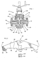
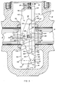
- Fig. 1 is a sectional view, certain portions shown in elevation, of the gate valve structure embodying the present invention shown in the embodiment illustrated in Figs. 3 and 4; Fig. 2 is a front view of the rocker arm and bearing block shown in Figs. 1, 3 and 4 removed from the valve chamber and with the bearing block and pin removed from the slot of the rocker arm; Fig. 3 is a sectional view of a portion of the gate valve assembly shown in Fig. 1 with the gate assembly in an intermediate position wherein the position responsive interlock assembly maintains the gate and segment in their fully collapsed position; Fig. 4 is a sectional view of a portion of the gate valve assembly shown in Fig. 1 with the dashed lines showing the gate assembly in its open position, and the solid lines showing the gate assembly in its closed position wherein the position responsive interlock allows the gate and segment to reach their expanded position; Fig. 5 is a plan view of a rocker arm and seat skirt comparatively illustrating the forces acting on the rocker arm when displaced from its closed position for the specific embodiment of the present invention and the embodiment illustrated in US-A-4. 188 014; and Fig. 6 is a perspective view of a modified rocker arm, gate and segment designed for use with the remainder of the gate assembly as shown in Figs. 1, 3 and 4 wherein the rocker arm and bearing block are exploded away from the gate and segment.
- In Figs. 1-4, there is illustrated the gate valve of the invention generally designated at 10.
Gate valve 10 includes avalve body 12 having avalve chamber 14, therein. Inlet andoutlet flow passages valve chamber 14.Flanges valve body 12 may be suitably connected to a pipeline or other flow system as is well known in the art. Abonnet 24 is bolted tovalve housing 12. Avalve stem 28 is positioned within thebonnet 24 in a conventional fashion for reciprocating movement with respect thereto, and has the outward end thereof (not illustrated) connected to ahandwheel 30 and theinward end 32 thereof connected to agate member 44 in a conventional fashion. Valvehousing 12 includes a pair ofannular recesses outlet flow passages adjacent valve chamber 14. Aseat element 40 is positioned or fit within each one ofannular recesses valve chamber 14 for reciprocal movement therein in a direction generally transverse to the direction of flow between open and closed positions.Gate assembly 34 is generally comprises of a gate orgate member 44, a segment orsegment member 52, and the position responsive interlock assembly generally designated at 42.Gate 44 andsegment 52 have parts therein which allow for the passage of fluid therethrough whengate assembly 34 is in an open position. -
Gate 44 includes a V-shaped recess 46 which defines upper andlower faces recess apex 51,opposite sides 49, and a generallyplanar sealing surface 50 facing thedownstream seat element 40.Segment 52 is positioned oppositegate 44 and has a complementary V-shaped face 54 which defines upper andlower faces face apex 59, a pair ofopposite sides 57, and an outwardly facingsurface 58. Whengate valve assembly 34 is collapsed, the V-shaped surfaces ofgate 44 andsegment 52 fit together so that recess andface apices - Forming an important feature of applicants' invention is the position responsive interlock assembly which allows
gate 44 andsegment 52 to expand whengate assembly 34 is in either an open or closed position thereby forming an effective seal between it andseats 40; but maintaininggate 42 andsegment 52 in collapsed position when traveling between the open and closed positions thereby reducing the chances thatseats 40 will bindgate assembly 34. Positionresponsive interlock assembly 42 is primarily comprised of aseat skirt 60 and arocker arm 80 and the accompanying structure connectingrocker arm 80 togate 44 andsegment 52.Seat skirt 60 is positioned betweensegment 52 and thedownstream seat element 40.Seat skirt 60 has a pair of generally parallel and spaced apart inwardly extendingelongate flanges 62 joined by a generallyplanar skirt body 74. Figs. 1 and 3-4 illustrate only oneflange 62 and hereinafter only the illustratedflange 62 and the structure associated therewith will be discussed.Flange 62 includes an elevated smooth slidingsurface 64 withbeveled portions opposite ends - An elongate member or
rocker arm 80 hasopposite ends edges projections opposite ends Projections sliding surfaces Rocker arm 80 further includes acircular aperture 100 and arectangular slot 102. Abearing block 104 has a cylindricallyshaped passageway 106 therein and is slidably received withinslot 102 for only longitudinal movement therein. Apivot pin 108 extends fromside 49 ofgate 44 and is journaled withinaperture 100. Abearing pin 110 extends fromside 57 ofsegment 52 and is journaled withinbearing block passageway 106. Thus,rocker arm 80 is pivotally connected togate 44, and pivotally and slidably connected tosegment 52. - Referring to Fig. 3,
rocker arm 80 is aligned in the general direction of movement of expandinggate valve assembly 34 so as to be in its so-called locking position.Sliding surfaces projections surface 64 ofskirt flange 62 so thatrocker arm 80 slides alongskirt flange 62 and is prevented from pivoting. Consequently,gate 44 andsegment 52 are maintained in their collapsed position as along assliding surfaces surface 64. - Referring to Fig. 4, when expanding
gate valve assembly 34 approaches its closed position,segment 52 encounters the lower portion ofvalve chamber 14 and ceases its downward movement.Skirt flange 62 is dimensioned so that just prior tosegment 52 encounteringvalve chamber 14,lower projection 88 passes the flange end 68 (the end nearest the bottom of valve chamber 14) wherebyrocker arm 80 is then free to pivot aboutpivot pin 108 in a counter clockwise direction as viewed in Figs. 1, 3 and 4. Aftersegment 52 has ceased moving,gate 44 continues to move downward a slight distance relative thereto which displacespivot pin 108 relative to bearingpin 110 from their original alignment. In response to this displacement,rocker arm 80 rotates in a counter clockwise direction as viewed in Figs. 1, 3 and 4. Asgate valve assembly 34 moves into its closed position the upper faces of V-shaped recess 46 andface 54 wedge together wherebygate 44 andsegment 52 expand away from each other bybearing block 104 and bearingpin 110 moving through aslot 102. The contact stresses associated with this movement are distributed bybearing block 104 to a sufficient degree such that no galling ofbearing pin 110,bearing block 104 orslot 102 occurs whereby premature maintenance and shutdown of the valve are reduced. - Upon the initial upward movement of
valve stem 28 that displacesgate valve assembly 34 from its closed position,gate 44 moves upwardly relative tosegment 52. As a result thereof,pivot pin 108 and bearingpin 110 move the general transverse alignment androcker arm 80 simultaneously rotates clockwise into its locking position. - While in its closed position, a significant fluid pressure is built up on the upstream side of expanding
gate valve assembly 34 which causesrocker arm 80 to exert a potentially damaging blow to skirtflange 62. Thus, it is advantageous that applicants'rocker arm 80 andskirt flange 62 are dimensioned so thatrocker arm 80strikes skirt flange 62 at a location where it is supported byvalve seat 40 and thus, reduces the possiblity thatskirt flange 62 would be damaged. - Referring to Fig. 5, when
gate valve assembly 34 is collapsed from its closed position,rocker arm 80 tends to rotate about the point (point "b"). Therocker arm projection 88 engages the beveled portion ofskirt flange 62, and provides a resistive force at point "a" torocker arm 80 pivoting about its intended pivot point which is the point whererocker arm 80 is pivotally connected to gate 44 (illustrated as point "b"). The force (represented by force vector F2) that pushes on therocker arm 80 acts over the perpendicular distance "c" to aid in overcoming the resistance of thegate 44 andsegment 52 to remain in the wedged position. - Still referring to Fig. 5, United States Patent No. 4,188,014 shows a device that has the pivotal connection between the gate assembly and rocker arm at a point (point "d") substantially closer to the edge of the rocker arm adjacent the seat skirt flange than applicants' pivotal connection point "b". The moment of force F2 about point "d" equals the magnitude of force F2 times distance "e". Since distance "c" is greater than distance "e" by distance "f", applicants' force F2 does not have to be as great as similar forces associated with an earlier device (United States Patent No. 4,188,014) to overcome the same resistive force at point "a"; and applicants' invention provides an improved ability to overcome any tendency on the part of the rocker arm to rotate about point a
- The rocker arm displays the same tendency to improperly rotate when the gate valve is displaced from its open position as when displaced from its closed position. It is overcome in a fashion similar to that described above so that the above discusion will suffice for any further discussion of this aspect of applicants' invention when the gate valve is displaced from its open position.
- In a manner generally similar to that previously described for
gate valve assembly 34 moving into its closed position,upper projection 87 ofrocker arm 80 passes oneend 66 offlange 62 just prior tosegment 52 encountering the bonnet so thatrocker arm 80 is free to rotate in a clockwise direction in response to the displacement ofpivot pin 108 whengate 44 moves upwardly relative tosegment 52.Gate 44 andsegment 52 also expand away from each other by movement ofbearing block 104 and bearingpin 110 throughslot 102. - The initial downward movement of valve stem 28
causes gate 44 to move downwardly relative tosegment 52 which in turn causespivot pin 108 andbearing pin 110 to move into general transverse alignment androcker arm 80 to rotate counter clockwise back into its locking position whilegate 44 andsegment 52 simultaneously collapse together. - Fig. 6 illustrates a modification of the rocker arm and adjacent sides of the gate and segment of the previously described specific embodiment. The
adjacent sides gate 44A andsegment 52A, respectively, contain arecess 120 therein.Recess 120 has abottom surface 122 and anupstanding side surface 124. Pivot pin 108A andbearing pin 110A extend outwardly from those portions ofbottom surface 122 contained ingate 44A andsegment 52A, respectively. Rocker arm 80A includes ashoulder 126 protruding therefrom.Shoulder 126 has acylindrical passageway 128 therein that joins aperture 100A, and asquare passageway 130 therein that joins slot 102A. Pivot pin 108A is journaled withincylindrical passageway 128 and aperture 100A.Bearing block 104A is slidably received withinsquare passageway 130 and the slot 102A.Bearing pin 110 A is journaled withinpassageway 106A. -
Recess 120 andshoulder 126 are dimensioned so as to not restrict the operative movement of rocker arm 80A so that the modified structure functions in a manner identical to that of the unmodified specific embodiment described above.Shoulder 126 in cooperation withrecess 120 provides additional support to rocker arm 80A so that it may adequately perform its intended function in larger sized applications. - It is seen that applicants' invention provides an expanding gate valve assembly that has an improved position responsive interlock assembly that reduces contact stresses that occur when the gate and segment move laterally of each other. Further, applicants' seat skirt is relatively inexpensive to manufacture, and is of an optimum strength along its length thereof. The rocker arm and seat skirt are positioned so that upon displacement of the valve from its closed position the rocker arm strikes the seat skirt at a point where it is supported by the seat. Finally, applicants' rocker arm more easily overcomes its tendency to rotate about the point where it engages the skirt flange when the gate valve assembly is displaced from its fully expanded position.
Claims (3)
Priority Applications (2)
| Application Number | Priority Date | Filing Date | Title |
|---|---|---|---|
| EP81890124A EP0070350B1 (en) | 1981-07-21 | 1981-07-21 | Expanding gate valve with position responsive interlock |
| AT81890124T ATE16842T1 (en) | 1981-07-21 | 1981-07-21 | EXPANSION VALVE WITH POSITIONAL LOCKING. |
Applications Claiming Priority (1)
| Application Number | Priority Date | Filing Date | Title |
|---|---|---|---|
| EP81890124A EP0070350B1 (en) | 1981-07-21 | 1981-07-21 | Expanding gate valve with position responsive interlock |
Publications (2)
| Publication Number | Publication Date |
|---|---|
| EP0070350A1 EP0070350A1 (en) | 1983-01-26 |
| EP0070350B1 true EP0070350B1 (en) | 1985-12-04 |
Family
ID=8188761
Family Applications (1)
| Application Number | Title | Priority Date | Filing Date |
|---|---|---|---|
| EP81890124A Expired EP0070350B1 (en) | 1981-07-21 | 1981-07-21 | Expanding gate valve with position responsive interlock |
Country Status (2)
| Country | Link |
|---|---|
| EP (1) | EP0070350B1 (en) |
| AT (1) | ATE16842T1 (en) |
Families Citing this family (1)
| Publication number | Priority date | Publication date | Assignee | Title |
|---|---|---|---|---|
| US6164622A (en) * | 1999-10-22 | 2000-12-26 | Daniel Valve Company, Inc. | Compact expanding gate valve |
Family Cites Families (5)
| Publication number | Priority date | Publication date | Assignee | Title |
|---|---|---|---|---|
| US2855175A (en) * | 1953-06-19 | 1958-10-07 | Calvin D Dunbar | Gate valve |
| US3006601A (en) * | 1958-03-28 | 1961-10-31 | Acf Ind Inc | Seat for gate valve |
| US3051434A (en) * | 1959-01-09 | 1962-08-28 | Acf Ind Inc | Back seating for valve stems |
| US4193577A (en) * | 1978-10-10 | 1980-03-18 | Acf Industries, Incorporated | Expanding gate valve with axially flexed spring plate |
| US4188014A (en) * | 1978-10-11 | 1980-02-12 | Acf Industries, Incorporated | Gate valve with position responsive interlock |
-
1981
- 1981-07-21 AT AT81890124T patent/ATE16842T1/en not_active IP Right Cessation
- 1981-07-21 EP EP81890124A patent/EP0070350B1/en not_active Expired
Also Published As
| Publication number | Publication date |
|---|---|
| EP0070350A1 (en) | 1983-01-26 |
| ATE16842T1 (en) | 1985-12-15 |
Similar Documents
| Publication | Publication Date | Title |
|---|---|---|
| US4350179A (en) | Valve assembly with relief groove | |
| US4428396A (en) | Adjustable valve assembly | |
| US5449144A (en) | Faucet valve with safety handle | |
| EP0898672B1 (en) | Protected soft seat with secondary hard seat | |
| EP0237681B1 (en) | Check valve | |
| US4881719A (en) | Gate valve | |
| US3289694A (en) | Ball check valve with particular cage means | |
| US7931251B2 (en) | Expanding gate valve | |
| US5211373A (en) | Gate valve having expanding gate and floating seats | |
| US4231549A (en) | Valve stem and valve disc connection for a diaphragm valve | |
| CA2002747C (en) | Gate valve with supplemental actuator | |
| US3930515A (en) | Pneumatic control system and valve construction therefor or the like | |
| EP0886091B1 (en) | Asymmetric seal segment configuration for a valve | |
| US4334666A (en) | Expanding gate valve with position responsive interlock | |
| US4188014A (en) | Gate valve with position responsive interlock | |
| US5169123A (en) | Steel ball valve | |
| US20040011986A1 (en) | Combination face and plug seal | |
| EP0404341B1 (en) | Sealing shroud port timing valve for two-stroke cycle engine | |
| US4700782A (en) | Flow control valve for use in oil and gas wells and the like | |
| US4480659A (en) | Gate stop valve | |
| US6349920B1 (en) | Poppet valve shaping for quick valve opening | |
| GB2075637A (en) | Expanding gate valve | |
| EP0070350A1 (en) | Expanding gate valve with position responsive interlock | |
| EP0465651B1 (en) | Pressure control valve | |
| US4279404A (en) | Guide arrangement for expanding gate valves |
Legal Events
| Date | Code | Title | Description |
|---|---|---|---|
| PUAI | Public reference made under article 153(3) epc to a published international application that has entered the european phase |
Free format text: ORIGINAL CODE: 0009012 |
|
| AK | Designated contracting states |
Designated state(s): AT GB IT |
|
| 17P | Request for examination filed |
Effective date: 19830716 |
|
| GRAA | (expected) grant |
Free format text: ORIGINAL CODE: 0009210 |
|
| ITF | It: translation for a ep patent filed | ||
| AK | Designated contracting states |
Designated state(s): AT GB IT |
|
| REF | Corresponds to: |
Ref document number: 16842 Country of ref document: AT Date of ref document: 19851215 Kind code of ref document: T |
|
| PGFP | Annual fee paid to national office [announced via postgrant information from national office to epo] |
Ref country code: AT Payment date: 19860627 Year of fee payment: 6 |
|
| PLBE | No opposition filed within time limit |
Free format text: ORIGINAL CODE: 0009261 |
|
| STAA | Information on the status of an ep patent application or granted ep patent |
Free format text: STATUS: NO OPPOSITION FILED WITHIN TIME LIMIT |
|
| 26N | No opposition filed | ||
| PG25 | Lapsed in a contracting state [announced via postgrant information from national office to epo] |
Ref country code: AT Effective date: 19880721 |
|
| PGFP | Annual fee paid to national office [announced via postgrant information from national office to epo] |
Ref country code: GB Payment date: 19930611 Year of fee payment: 13 |
|
| PG25 | Lapsed in a contracting state [announced via postgrant information from national office to epo] |
Ref country code: GB Effective date: 19940721 |
|
| GBPC | Gb: european patent ceased through non-payment of renewal fee |
Effective date: 19940721 |