EP0070129B1 - Continuous filled envelope assembly - Google Patents
Continuous filled envelope assembly Download PDFInfo
- Publication number
- EP0070129B1 EP0070129B1 EP82303483A EP82303483A EP0070129B1 EP 0070129 B1 EP0070129 B1 EP 0070129B1 EP 82303483 A EP82303483 A EP 82303483A EP 82303483 A EP82303483 A EP 82303483A EP 0070129 B1 EP0070129 B1 EP 0070129B1
- Authority
- EP
- European Patent Office
- Prior art keywords
- web
- marginal
- perforations
- webs
- continuous
- Prior art date
- Legal status (The legal status is an assumption and is not a legal conclusion. Google has not performed a legal analysis and makes no representation as to the accuracy of the status listed.)
- Expired
Links
Images

Classifications
-
- B—PERFORMING OPERATIONS; TRANSPORTING
- B42—BOOKBINDING; ALBUMS; FILES; SPECIAL PRINTED MATTER
- B42D—BOOKS; BOOK COVERS; LOOSE LEAVES; PRINTED MATTER CHARACTERISED BY IDENTIFICATION OR SECURITY FEATURES; PRINTED MATTER OF SPECIAL FORMAT OR STYLE NOT OTHERWISE PROVIDED FOR; DEVICES FOR USE THEREWITH AND NOT OTHERWISE PROVIDED FOR; MOVABLE-STRIP WRITING OR READING APPARATUS
- B42D5/00—Sheets united without binding to form pads or blocks
- B42D5/02—Form sets
- B42D5/023—Continuous form sets
- B42D5/025—Mailer assemblies
Definitions
- This invention relates to a continuous business form assembly and, more specifically to a continuous filled envelope assembly.
- Continuous filled envelope assemblies of the type indicated in the pre-characterising portion of Claim 1 are disclosed in U.S. Patent Specification No. 3941308.
- known continuous filled envelope assemblies have included insert webs each including inserts extending laterally from a single continuous, non-marginal feed strip, and insert webs each including inserts extending from two continuous, marginal feed strips. While these assemblies may have proven useful the envelope described in U.S. Patent No. 3941308 does not have an advantage of the envelope described in British Specification No. 1128634 which is accurate feeding of the insert webs with the envelope webs. The British Specification No. 1128634 does not have an advantage of the U.S. Specification No. 3941308 which is laterally abbreviated insert webs capable of being fed and collated independent of the envelope webs.
- U.S. Specification No. 4095695 describes a series of connected stuffed sealed envelope assemblies which may include three invoice plies including an invoice ply and two envelope plies.
- Another object of the invention is to provide a continuous, filled envelope assembly which includes insert webs capable of being accurately fed with the envelope webs and also laterally and/ or longitudinally abbreviated insert webs capable of being fed and collated independent of the envelope webs.
- Another object of the invention is to provide a continuous, filled envelope assembly which is inexpensive of manufacture, pleasing of appearance, and readily useful through ease of removal of insert material.
- Another object of the invention is to provide a continuous filled envelope assembly which is compactly and neatly stored, substantially without tenting.
- a continuous business form assembly constituting a filled envelope assembly comprises at least three webs each of the webs being continuous in a longitudinal direction and having two spaced marginal edges in a transverse direction, a marginal row of spaced feed holes extending along each marginal edge, a line of marginal perforations extending along each marginal row of spaced feed holes, the marginal row of spaced feed holes and marginal perforations thereby defining two continuous, marginal feed strips along two marginal edges and each of the three webs further having a line of non-marginal perforations adjacent a first of the lines of marginal perforations and two spaced transverse lines of perforations, the line of non-marginal perforations defining a non-marginal strip adjacent one of the marginal feed strips and the transverse lines of perforations defining a sheet on the webs;
- the intermediate third web defining transversely extending die cuts along the transverse lines of perforations of the intermediate third web between the marginal lines of perforations thereof, the die cuts thereby interrupting the transverse lines of perforations of the intermediate web between the marginal lines of perforations thereof;
- the first web being attached to the second web along the transverse lines of perforations and through the die cuts, to form an envelope of the sheets of the first and second webs and an envelope insert of the third web;
- the intermediate third web has a non-marginal row of spaced feed holes extending along the line of non-marginal perforations of the intermediate third web in the non-marginal strip of the intermediate third web, the non-marginal strip of the third web thereby being a non-marginal feed strip;
- the continuous business forms assembly further comprises a non-continuous fourth web superimposed on the intermediate third web between the intermediate third web and the first web, the non-continuous fourth web having transverse edges in the transverse direction along the die cuts and marginal edges spaced in the transverse direction, one of the marginal edges of the non-continuous fourth web extending along the first of the lines of marginal perforations of the third web, the fourth web further having a line of marginal perforations superimposed upon the line of non-marginal perforations of the third web and a row of spaced feed holes superimposed on the non-marginal row of spaced feed holes of the third web, the non-continuous fourth web being attached along the non-marginal strip of the third web, to the third web.
- Figure 1 is a plan view of the preferred embodiment of the invention, with portions of the webs of the embodiment cut away to reveal underlying details and
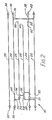
- Figure 2 is a cross-section, schematic view of the preferred embodiment, taken along line 2-2 in Figure 1.
- the preferred embodiment of the invention is a continuous, filled envelope assembly 10.
- the assembly 10 provides a series of separate, filled envelopes, such as envelope 12 in Figure 1, and a series of separable record forms, such as form 14 in Fig. 1.
- the envelopes 12 are filled with insert material including insert forms, such as insert form 16 in Fig. 1, and an insert envelope, such as insert envelope 18 in Fig. 1.
- the record forms 14, envelopes 12 and insert forms 16 are imprinted in one operation with address and other information. Imprinting is accomplished through the use of pressure-sensitive transfer material on the backs of the record forms 14 and within the envelopes 12.
- the envelopes 12 and forms 14 are separated, with the envelope 12 delivered to recipients and the forms 14 retained as evidence records of delivery. The recipients may open the envelope 12 and use the inserts as desired or instructed.
- the insert envelope 18 may be used as a return envelope for a message on the insert form 16.
- the insert envelope 18 may be used as a return envelope for payment of an account, where two insert forms 16 are provided as statements of the account, one for retention and one for return.
- the assembly 10 includes first and second webs, respectively 20, 22 which form the envelopes 12, third, fourth and fifth webs respectively 24, 26, 28, which form the inserts 16, 18; and sixth web 30, which forms the record forms 14.
- the third web 24 is intermediate, or between, the first and second webs 20, 22.
- the fourth and fifth webs 26, 28 are atop the third web 24, and the sixth web 30 is atop the first web 20.
- the first, second, third and sixth webs 20,22,24 and 30 are each continuous in a longitudinal direction, which is the vertical direction in Fig. 1.
- Each web 20, 22, 24, 30 has two longitudinally extended marginal edges 32, 34 which are spaced apart in a transverse direction, perpendicular to the longitudinal direction.
- a marginal row of spaced feed holes 36 extends along each edge 32, 34 of the webs 20, 22, 24, 30.
- a marginal line of perforations 38 extends along each marginal row 36.
- the marginal lines and rows 38, 36 define marginal feed stripes 40, and thus, each web 20, 22, 24, 30 has two removable marginal feed strips 40.
- the webs 20, 22, 24, 30 each further has a series of longitudinally spaced, transverse lines of perforations 42 as in Figure 1.
- the lines 42 of the webs 20, 22 and 30 extend across the webs from edge 32 to edge 34.
- the lines 42 of the third web 24 extend inward of the edges 32, 34 of the web 24, to rectangular die cuts 44.
- the lines 42 of the webs 20, 22, 24, 30 all define sheets 46 on the webs, and thus, each web 20, 22, 24, 30 has a series of separable sheets 46.
- the sheets 46 of the web 24 are joined only along the marginal strips 40.
- the die cuts 44 eliminate any joint between the sheets 46 of the web 24 between the perforation lines 38.
- the longitudinal width of the die cuts 44 provides space for two glue lines 80, to be described, adjacent the transverse lines of perforations 42. Space is provided such that the sheets 46 of the web 24 are free of the glue lines 80.
- the webs 20, 22 and 24 have a non-marginal line of perforations 48 extending along a single marginal feed strip 40.
- the lines 48 define removable non-marginal strips 50 on the webs 20, 22, 24.
- the web 30 has no line 48, or strip 50.
- the webs 20, 22, 24 and 30 are superimposed. That is, the webs 20, 22, 24, 30 overlie one another, in the sequence previously described, with their common features superimposed, aligned or matched, one atop the other. Thus, the edges 32, 34 of the webs 20, 22, 24 and 30 are superimposed; the perforation lines 38, 42, 48 of the webs 20, 22, and 24 and 30 are aligned; the feed hole rows 36 are matched; and the sheets 46 and strips 40, 50 are placed on atop another.
- the sheets 46 of the sixth web 30 form the record forms 14.
- the sheets 46 of the first and second webs 20, 22 form the envelopes 12.
- the sheets 46 of the third web 24, in combination with the remaining webs 26, 28 forms the inserts.
- the web 30 is not attached to the webs 20, 22.
- the webs 20, 22 are attached to each other through the die cuts 44.
- the webs 20, 22, 24, 26 and 28 are all attached as a unit, as will be described.
- the webs 26, 28 are non-continuous. Each web 26, 28 has a first marginal edge 54 extending along and between one of the marginal perforation lines 38, and the non-marginal perforation line 48, of the web 24. The web 26 extends transversely across the web 24 to a marginal edge 56 adjacent a second non-marginal perforation line 58 of the web 24, and the web 28 extends a lesser distance across the web 24 to a marginal edge 60 of the web 28 adjacent a non-marginal fold line 62 of the web 24. In the longitudinal direction, each web 26, 28 has spaced transverse edges 64 aligned with the edges of the die cuts 44.
- the non-continuous webs 26, 28 are thus formed in series of unconnected sheets 66.
- Each sheet 66 has a marginal row of spaced feed holes 68 along the edge 54, which are superimposed with a non-marginal row of spaced feed holes 70 of the web 24.
- Each sheet 66 has a marginal line of perforations 72 superimposed on the non-marginal lines 48.
- the non-marginal strip 50 of the third web 24 is thus a feed strip, and the sheets 66 define discontinuous feed strips 74 superimposed on the feed strip 50 of the third web 24.
- the webs 20, 22, 24, 26 and 28 are all attached, as a unit.
- Continuous glue lines 76 extend along the marginal perforation lines 38 of the webs 20 and 22, inward of the feed strips 40.
- the glue lines 76 attach the web 20 to the webs 22, 24 and 26, and the web 22 to the web 24.
- the web 20 is attached to the web 22 in the area of the die cuts 44, to the web 24 adjacent the non-marginal perforation line 58 of the web 24, and to the web 26 in the area of the feed strip 74 of the web 26.
- The, web 22 is attached to the web 24 in the area of the non-marginal feed strip 50 and to the web 24 between the non-marginal perforation line 58 and the adjacent feed strip 40 of the web 24.
- a discontinuous glue line on the webs 24, 28 superimposed on one of the continuous glue lines 76 attaches the feed strip 74 of the web 26 to the feed strip 74 of the web 28, and the feed strip 74 of the web 28 to the web 24.
- Transverse glue lines 80 further join the webs 20, 22.
- the lines 80 extend between the lines 76, in the area of the die cuts 44.
- the lines 80 are paired to a die cut 44, one on either side of each transverse perforation line 42.
- Final glue lines 82, 84 join the web 28 to the web 24, forming insert envelopes 18 of the sheets 66, 46 of the two webs.
- the webs 26 and 28 may be fed together and attached to the web 24 through the use of the feed strips 50, 74 of the webs 24, 26, 28.
- the unit of webs 24, 26, 28 may then be fed and attached to the webs 20, 22 and fed to the web 30, through the feed strips 40 of the webs 20, 22, 24, 30.
- the assembly 10 may then be fed by strips 40 through a printer and such other equipment as desired.
- Separate envelopes 12 and record sheets 14 may be formed by perforation of the lines 38, 42. This perforation removes the strips 40, and separates the envelopes from each other.
- a recipient of an envelope 12 may receive a neat, sealed envelope 12.
- the recipient may open the envelope 12 by removing the non-marginal feed strips 50 of the webs 20, 22, thereby simultaneously removing the feed strips 50, 74 of the webs 24, 26, 28.
- the inserts 16,18 can then be pulled and separated at the perforation 58 to remove these inserts from the envelope 12 for use.
- the perforation line 58 of the web 24 is weakened such that it separates upon the application of less transverse force than required to separate perforation line 62 of web 24.
- a user may then, as most preferred, pull the insert form and envelope 16, 18 from the envelope by application of force to the strips 50, 74 of the webs 20, 22, 24, 26, 28. As so constructed, form and envelope 16, 18 and strips 50, 74 separate from the envelope 12 as a unit.
Landscapes
- Making Paper Articles (AREA)
- Packages (AREA)
- Containers And Plastic Fillers For Packaging (AREA)
- Buffer Packaging (AREA)
- Preparation Of Compounds By Using Micro-Organisms (AREA)
- Medicines Containing Material From Animals Or Micro-Organisms (AREA)
- Compounds Of Unknown Constitution (AREA)
- Diaphragms For Electromechanical Transducers (AREA)
- Revetment (AREA)
- Container Filling Or Packaging Operations (AREA)
- Sheets, Magazines, And Separation Thereof (AREA)
- Paper (AREA)
- Supply Devices, Intensifiers, Converters, And Telemotors (AREA)
- Acyclic And Carbocyclic Compounds In Medicinal Compositions (AREA)
- Error Detection And Correction (AREA)
Abstract
Description
- This invention relates to a continuous business form assembly and, more specifically to a continuous filled envelope assembly.
- Continuous filled envelope assemblies of the type indicated in the pre-characterising portion of
Claim 1 are disclosed in U.S. Patent Specification No. 3941308. As shown in U.S. Patent 3941308, known continuous filled envelope assemblies have included insert webs each including inserts extending laterally from a single continuous, non-marginal feed strip, and insert webs each including inserts extending from two continuous, marginal feed strips. While these assemblies may have proven useful the envelope described in U.S. Patent No. 3941308 does not have an advantage of the envelope described in British Specification No. 1128634 which is accurate feeding of the insert webs with the envelope webs. The British Specification No. 1128634 does not have an advantage of the U.S. Specification No. 3941308 which is laterally abbreviated insert webs capable of being fed and collated independent of the envelope webs. - Also U.S. Specification No. 4095695 describes a series of connected stuffed sealed envelope assemblies which may include three invoice plies including an invoice ply and two envelope plies.
- It is an object of the present invention to provide a business form assembly constituting an improved, continuous, filled envelope assembly.
- Another object of the invention is to provide a continuous, filled envelope assembly which includes insert webs capable of being accurately fed with the envelope webs and also laterally and/ or longitudinally abbreviated insert webs capable of being fed and collated independent of the envelope webs.
- Another object of the invention is to provide a continuous, filled envelope assembly which is inexpensive of manufacture, pleasing of appearance, and readily useful through ease of removal of insert material.
- Another object of the invention is to provide a continuous filled envelope assembly which is compactly and neatly stored, substantially without tenting.
- According to the present invention a continuous business form assembly constituting a filled envelope assembly comprises at least three webs each of the webs being continuous in a longitudinal direction and having two spaced marginal edges in a transverse direction, a marginal row of spaced feed holes extending along each marginal edge, a line of marginal perforations extending along each marginal row of spaced feed holes, the marginal row of spaced feed holes and marginal perforations thereby defining two continuous, marginal feed strips along two marginal edges and each of the three webs further having a line of non-marginal perforations adjacent a first of the lines of marginal perforations and two spaced transverse lines of perforations, the line of non-marginal perforations defining a non-marginal strip adjacent one of the marginal feed strips and the transverse lines of perforations defining a sheet on the webs;
- the three webs being superimposed with the feed holes, perforations, feed strips, and sheets thereof superimposed and the three webs being attached along the non-marginal strips;
- two of the three webs being first and second webs and the other of the three webs being an intermediate third web located between the first and second webs, the intermediate third web defining transversely extending die cuts along the transverse lines of perforations of the intermediate third web between the marginal lines of perforations thereof, the die cuts thereby interrupting the transverse lines of perforations of the intermediate web between the marginal lines of perforations thereof;
- the first web being attached to the second web along the transverse lines of perforations and through the die cuts, to form an envelope of the sheets of the first and second webs and an envelope insert of the third web;
- characterised in that the intermediate third web has a non-marginal row of spaced feed holes extending along the line of non-marginal perforations of the intermediate third web in the non-marginal strip of the intermediate third web, the non-marginal strip of the third web thereby being a non-marginal feed strip;
- the continuous business forms assembly further comprises a non-continuous fourth web superimposed on the intermediate third web between the intermediate third web and the first web, the non-continuous fourth web having transverse edges in the transverse direction along the die cuts and marginal edges spaced in the transverse direction, one of the marginal edges of the non-continuous fourth web extending along the first of the lines of marginal perforations of the third web, the fourth web further having a line of marginal perforations superimposed upon the line of non-marginal perforations of the third web and a row of spaced feed holes superimposed on the non-marginal row of spaced feed holes of the third web, the non-continuous fourth web being attached along the non-marginal strip of the third web, to the third web.
- The preferred embodiment of the invention is described in relation to the accompanying drawing. The drawing includes two figures, briefly described as follows:
- Figure 1 is a plan view of the preferred embodiment of the invention, with portions of the webs of the embodiment cut away to reveal underlying details and
- Figure 2 is a cross-section, schematic view of the preferred embodiment, taken along line 2-2 in Figure 1.
- Referring to the accompanying drawing, the preferred embodiment of the invention is a continuous, filled
envelope assembly 10. - The
assembly 10 provides a series of separate, filled envelopes, such asenvelope 12 in Figure 1, and a series of separable record forms, such asform 14 in Fig. 1. Theenvelopes 12 are filled with insert material including insert forms, such asinsert form 16 in Fig. 1, and an insert envelope, such asinsert envelope 18 in Fig. 1. As conventional, the record forms 14,envelopes 12 and insertforms 16 are imprinted in one operation with address and other information. Imprinting is accomplished through the use of pressure-sensitive transfer material on the backs of the record forms 14 and within theenvelopes 12. Afterward, theenvelopes 12 andforms 14 are separated, with theenvelope 12 delivered to recipients and theforms 14 retained as evidence records of delivery. The recipients may open theenvelope 12 and use the inserts as desired or instructed. As an example, theinsert envelope 18 may be used as a return envelope for a message on theinsert form 16. As another example, theinsert envelope 18 may be used as a return envelope for payment of an account, where two insertforms 16 are provided as statements of the account, one for retention and one for return. - To provide the filled
envelopes 12 and record forms 14, theassembly 10 includes first and second webs, respectively 20, 22 which form theenvelopes 12, third, fourth and fifth webs respectively 24, 26, 28, which form theinserts sixth web 30, which forms the record forms 14. Thethird web 24 is intermediate, or between, the first andsecond webs fifth webs third web 24, and thesixth web 30 is atop thefirst web 20. - The first, second, third and
sixth webs web marginal edges edge webs perforations 38 extends along eachmarginal row 36. The marginal lines androws marginal feed stripes 40, and thus, eachweb - The
webs perforations 42 as in Figure 1. Thelines 42 of thewebs edge 32 to edge 34. Thelines 42 of thethird web 24 extend inward of theedges web 24, to rectangular die cuts 44. Thelines 42 of thewebs sheets 46 on the webs, and thus, eachweb separable sheets 46. - The
sheets 46 of theweb 24 are joined only along the marginal strips 40. The die cuts 44 eliminate any joint between thesheets 46 of theweb 24 between the perforation lines 38. The longitudinal width of the die cuts 44 provides space for twoglue lines 80, to be described, adjacent the transverse lines ofperforations 42. Space is provided such that thesheets 46 of theweb 24 are free of the glue lines 80. - The
webs perforations 48 extending along a singlemarginal feed strip 40. Thelines 48 define removablenon-marginal strips 50 on thewebs web 30 has noline 48, orstrip 50. - The
webs webs edges webs webs feed hole rows 36 are matched; and thesheets 46 and strips 40, 50 are placed on atop another. - The
sheets 46 of thesixth web 30 form the record forms 14. Thesheets 46 of the first andsecond webs envelopes 12. Thesheets 46 of thethird web 24, in combination with the remainingwebs envelopes 12, theweb 30 is not attached to thewebs envelopes 12, thewebs webs - The
webs web marginal edge 54 extending along and between one of themarginal perforation lines 38, and thenon-marginal perforation line 48, of theweb 24. Theweb 26 extends transversely across theweb 24 to amarginal edge 56 adjacent a secondnon-marginal perforation line 58 of theweb 24, and theweb 28 extends a lesser distance across theweb 24 to amarginal edge 60 of theweb 28 adjacent anon-marginal fold line 62 of theweb 24. In the longitudinal direction, eachweb transverse edges 64 aligned with the edges of the die cuts 44. - The
non-continuous webs unconnected sheets 66. Eachsheet 66 has a marginal row of spacedfeed holes 68 along theedge 54, which are superimposed with a non-marginal row of spacedfeed holes 70 of theweb 24. Eachsheet 66 has a marginal line ofperforations 72 superimposed on thenon-marginal lines 48. Thenon-marginal strip 50 of thethird web 24 is thus a feed strip, and thesheets 66 define discontinuous feed strips 74 superimposed on thefeed strip 50 of thethird web 24. - The
webs Continuous glue lines 76 extend along themarginal perforation lines 38 of thewebs web 20 to thewebs web 22 to theweb 24. Theweb 20 is attached to theweb 22 in the area of the die cuts 44, to theweb 24 adjacent thenon-marginal perforation line 58 of theweb 24, and to theweb 26 in the area of thefeed strip 74 of theweb 26. The,web 22 is attached to theweb 24 in the area of thenon-marginal feed strip 50 and to theweb 24 between thenon-marginal perforation line 58 and theadjacent feed strip 40 of theweb 24. A discontinuous glue line on thewebs continuous glue lines 76, attaches thefeed strip 74 of theweb 26 to thefeed strip 74 of theweb 28, and thefeed strip 74 of theweb 28 to theweb 24. -
Transverse glue lines 80 further join thewebs lines 80 extend between thelines 76, in the area of the die cuts 44. Thelines 80 are paired to a die cut 44, one on either side of eachtransverse perforation line 42. -
Final glue lines web 28 to theweb 24, forminginsert envelopes 18 of thesheets - As should now be apparent, the
webs web 24 through the use of the feed strips 50, 74 of thewebs webs webs web 30, through the feed strips 40 of thewebs assembly 10 may then be fed bystrips 40 through a printer and such other equipment as desired.Separate envelopes 12 andrecord sheets 14 may be formed by perforation of thelines strips 40, and separates the envelopes from each other. - Thus, a recipient of an
envelope 12 may receive a neat, sealedenvelope 12. The recipient may open theenvelope 12 by removing the non-marginal feed strips 50 of thewebs webs inserts perforation 58 to remove these inserts from theenvelope 12 for use. - As most preferred, the
perforation line 58 of theweb 24 is weakened such that it separates upon the application of less transverse force than required to separateperforation line 62 ofweb 24. A user may then, as most preferred, pull the insert form andenvelope strips webs envelope envelope 12 as a unit. - With an assembly as described, accurate feeding of the intermediate web with the other webs is provided by the superimposed, marginal feed strips of the three webs. Independent feeding of the preferred intermediate web is provided by the marginal feed strip. Formation of the sheets of the first and second webs into an envelope with substantial freedom from tenting is provided by the die cuts. Ease of separation of the assembly into units is also provided by the die cuts, since separation of the sheets after removal of the marginal feed strips requires perforation of only. the first and second sheets.
Claims (4)
Priority Applications (1)
| Application Number | Priority Date | Filing Date | Title |
|---|---|---|---|
| AT82303483T ATE13651T1 (en) | 1981-07-13 | 1982-07-02 | CONTINUOUS SET OF ENVELOPES WITH INLAYS. |
Applications Claiming Priority (2)
| Application Number | Priority Date | Filing Date | Title |
|---|---|---|---|
| US06/282,589 US4645123A (en) | 1981-07-13 | 1981-07-13 | Continuous, filled envelope assembly with non-marginal spaced feed holes |
| US282589 | 1981-07-13 |
Publications (2)
| Publication Number | Publication Date |
|---|---|
| EP0070129A1 EP0070129A1 (en) | 1983-01-19 |
| EP0070129B1 true EP0070129B1 (en) | 1985-06-05 |
Family
ID=23082179
Family Applications (1)
| Application Number | Title | Priority Date | Filing Date |
|---|---|---|---|
| EP82303483A Expired EP0070129B1 (en) | 1981-07-13 | 1982-07-02 | Continuous filled envelope assembly |
Country Status (14)
| Country | Link |
|---|---|
| US (1) | US4645123A (en) |
| EP (1) | EP0070129B1 (en) |
| AT (1) | ATE13651T1 (en) |
| AU (1) | AU553182B2 (en) |
| DE (1) | DE3264029D1 (en) |
| DK (1) | DK313782A (en) |
| ES (1) | ES275692U (en) |
| FI (1) | FI75779C (en) |
| GR (1) | GR76207B (en) |
| IE (1) | IE53213B1 (en) |
| NO (1) | NO158213C (en) |
| NZ (1) | NZ201241A (en) |
| PT (1) | PT75231B (en) |
| ZA (1) | ZA824900B (en) |
Families Citing this family (11)
| Publication number | Priority date | Publication date | Assignee | Title |
|---|---|---|---|---|
| USRE32971E (en) * | 1982-03-12 | 1989-07-04 | Bedinghaus Business Forms, Inc. | Envelope assembly |
| US4475747A (en) * | 1983-02-28 | 1984-10-09 | Moore Business Forms, Inc. | Packing form |
| FI851725A7 (en) * | 1984-05-03 | 1986-10-31 | Moore Business Forms Inc | FOENSTERKUVERT MED TRYCKKAENSLIGT ADDRESSARK. |
| EP0223793A4 (en) * | 1985-06-06 | 1987-09-30 | Paper Ltd Comp | Multiple leaf ticket assemblies. |
| US4955526A (en) * | 1989-03-01 | 1990-09-11 | Uarco Inc. | Business form such as an envelope |
| GB2229962B (en) * | 1989-03-30 | 1992-11-11 | Moore Business Forms Inc | Improvements in return business forms assemblies |
| US4896822A (en) * | 1989-04-05 | 1990-01-30 | Moore Business Forms, Inc. | Apparatus and methods for forming mailers with inserts |
| US4938505A (en) * | 1989-08-11 | 1990-07-03 | Ncr Corporation | Business form for use in shipping parcels |
| US5172855A (en) * | 1991-04-01 | 1992-12-22 | Ncr Corporation | Continuous mailer form |
| US5429298A (en) * | 1993-07-30 | 1995-07-04 | Moore Business Forms, Inc. | Universal mailer |
| AU715206B2 (en) * | 1998-06-05 | 2000-01-20 | Axfite Pty. Ltd. | Laminated re-sealable envelope |
Family Cites Families (9)
| Publication number | Priority date | Publication date | Assignee | Title |
|---|---|---|---|---|
| US3104799A (en) * | 1963-09-24 | Envelope assembly | ||
| US3339827A (en) * | 1966-01-17 | 1967-09-05 | Varco Inc | Sealed envelope assembly with interior mailing material |
| US3554438A (en) * | 1968-06-24 | 1971-01-12 | Moore Business Forms Inc | Correspondence assembly |
| US4002290A (en) * | 1974-08-08 | 1977-01-11 | Moore Business Forms, Inc. | Envelope assembly |
| US3941308A (en) * | 1974-10-31 | 1976-03-02 | The Standard Register Company | Continuous mailer envelope assembly with inserts and method |
| US4108352A (en) * | 1976-05-07 | 1978-08-22 | Uarco Incorporated | Continuous business forms assembly with anti-tenting means |
| FR2378635A1 (en) * | 1977-01-26 | 1978-08-25 | Herve & Fils Sa | CONTINUOUS STRIP OF SEALED ENVELOPES WITH INTERIOR DOCUMENTS |
| US4095695A (en) * | 1977-04-18 | 1978-06-20 | Wallace Business Forms, Inc. | Stuffed sealed envelope assembly and method of making |
| US4277016A (en) * | 1978-04-11 | 1981-07-07 | Moore Business Forms | Envelope assembly |
-
1981
- 1981-07-13 US US06/282,589 patent/US4645123A/en not_active Ceased
-
1982
- 1982-07-02 AT AT82303483T patent/ATE13651T1/en not_active IP Right Cessation
- 1982-07-02 IE IE1617/82A patent/IE53213B1/en unknown
- 1982-07-02 EP EP82303483A patent/EP0070129B1/en not_active Expired
- 1982-07-02 DE DE8282303483T patent/DE3264029D1/en not_active Expired
- 1982-07-08 FI FI822435A patent/FI75779C/en not_active IP Right Cessation
- 1982-07-09 ZA ZA824900A patent/ZA824900B/en unknown
- 1982-07-12 NZ NZ201241A patent/NZ201241A/en unknown
- 1982-07-12 PT PT75231A patent/PT75231B/en not_active IP Right Cessation
- 1982-07-12 ES ES1982275692U patent/ES275692U/en active Pending
- 1982-07-12 AU AU85910/82A patent/AU553182B2/en not_active Ceased
- 1982-07-12 NO NO822416A patent/NO158213C/en unknown
- 1982-07-13 DK DK313782A patent/DK313782A/en not_active Application Discontinuation
- 1982-07-13 GR GR68748A patent/GR76207B/el unknown
Also Published As
| Publication number | Publication date |
|---|---|
| ES275692U (en) | 1984-03-16 |
| NO158213C (en) | 1988-08-03 |
| PT75231A (en) | 1982-08-01 |
| FI75779B (en) | 1988-04-29 |
| IE53213B1 (en) | 1988-08-31 |
| NO822416L (en) | 1983-01-14 |
| DK313782A (en) | 1983-01-14 |
| FI75779C (en) | 1988-08-08 |
| DE3264029D1 (en) | 1985-07-11 |
| IE821617L (en) | 1983-01-13 |
| NZ201241A (en) | 1984-08-24 |
| US4645123A (en) | 1987-02-24 |
| EP0070129A1 (en) | 1983-01-19 |
| PT75231B (en) | 1984-10-29 |
| FI822435A0 (en) | 1982-07-08 |
| AU8591082A (en) | 1983-01-20 |
| ZA824900B (en) | 1983-07-27 |
| AU553182B2 (en) | 1986-07-03 |
| NO158213B (en) | 1988-04-25 |
| GR76207B (en) | 1984-08-03 |
| FI822435L (en) | 1983-01-14 |
| ATE13651T1 (en) | 1985-06-15 |
Similar Documents
| Publication | Publication Date | Title |
|---|---|---|
| US3941308A (en) | Continuous mailer envelope assembly with inserts and method | |
| EP0354780B1 (en) | Mailer | |
| US4081127A (en) | Return envelope for mailer and method | |
| US4346916A (en) | Multiple ply business form and manifold assembly | |
| US4645123A (en) | Continuous, filled envelope assembly with non-marginal spaced feed holes | |
| US5040720A (en) | Return envelope mailer | |
| EP0274822B1 (en) | Method of making a personalized folder with pockets and page inserts from a continuous web | |
| US5360159A (en) | Mailers and business form assemblies for producing mailers | |
| US4440341A (en) | Return envelope mailer | |
| AU600926B2 (en) | Folded envelope and blank for forming same | |
| EP0129950B1 (en) | Continuous business assembly of combined mailers and top-opening return envelopes | |
| CA1336611C (en) | Business form such as an envelope | |
| EP0200456B1 (en) | Envelopes | |
| US4213639A (en) | Continuous business form assembly | |
| US4475747A (en) | Packing form | |
| US4171831A (en) | Continuous stationery assemblies | |
| USRE33570E (en) | Continuous filled envelope assembly with non-marginal spaced feed holes | |
| USRE33139E (en) | Packing form | |
| EP0143622A1 (en) | Improvements in business form assemblies | |
| EP0538995B1 (en) | Multiple part business form and related process | |
| US5038999A (en) | Continuous mailer assembly | |
| US5108346A (en) | Retaining a part within a business form | |
| EP0138501A2 (en) | Cut sheet mailer | |
| EP0128738A2 (en) | Mailing wrapper with reply envelope and response device from integral web | |
| US4795193A (en) | Booklet with return envelope |
Legal Events
| Date | Code | Title | Description |
|---|---|---|---|
| PUAI | Public reference made under article 153(3) epc to a published international application that has entered the european phase |
Free format text: ORIGINAL CODE: 0009012 |
|
| AK | Designated contracting states |
Designated state(s): AT BE CH DE FR GB IT LI LU NL SE |
|
| 17P | Request for examination filed |
Effective date: 19830211 |
|
| ITF | It: translation for a ep patent filed | ||
| GRAA | (expected) grant |
Free format text: ORIGINAL CODE: 0009210 |
|
| AK | Designated contracting states |
Designated state(s): AT BE CH DE FR GB IT LI LU NL SE |
|
| REF | Corresponds to: |
Ref document number: 13651 Country of ref document: AT Date of ref document: 19850615 Kind code of ref document: T |
|
| REF | Corresponds to: |
Ref document number: 3264029 Country of ref document: DE Date of ref document: 19850711 |
|
| PG25 | Lapsed in a contracting state [announced via postgrant information from national office to epo] |
Ref country code: LU Free format text: LAPSE BECAUSE OF NON-PAYMENT OF DUE FEES Effective date: 19850731 |
|
| ET | Fr: translation filed | ||
| PLBE | No opposition filed within time limit |
Free format text: ORIGINAL CODE: 0009261 |
|
| STAA | Information on the status of an ep patent application or granted ep patent |
Free format text: STATUS: NO OPPOSITION FILED WITHIN TIME LIMIT |
|
| 26N | No opposition filed | ||
| PGFP | Annual fee paid to national office [announced via postgrant information from national office to epo] |
Ref country code: AT Payment date: 19860609 Year of fee payment: 5 |
|
| PG25 | Lapsed in a contracting state [announced via postgrant information from national office to epo] |
Ref country code: AT Effective date: 19890702 |
|
| PG25 | Lapsed in a contracting state [announced via postgrant information from national office to epo] |
Ref country code: SE Effective date: 19890703 |
|
| PG25 | Lapsed in a contracting state [announced via postgrant information from national office to epo] |
Ref country code: LI Effective date: 19890731 Ref country code: CH Effective date: 19890731 |
|
| REG | Reference to a national code |
Ref country code: CH Ref legal event code: PL |
|
| PG25 | Lapsed in a contracting state [announced via postgrant information from national office to epo] |
Ref country code: DE Effective date: 19900403 |
|
| PGFP | Annual fee paid to national office [announced via postgrant information from national office to epo] |
Ref country code: BE Payment date: 19900626 Year of fee payment: 9 |
|
| PGFP | Annual fee paid to national office [announced via postgrant information from national office to epo] |
Ref country code: LU Payment date: 19900627 Year of fee payment: 9 |
|
| ITTA | It: last paid annual fee | ||
| PG25 | Lapsed in a contracting state [announced via postgrant information from national office to epo] |
Ref country code: BE Effective date: 19910731 |
|
| PGFP | Annual fee paid to national office [announced via postgrant information from national office to epo] |
Ref country code: NL Payment date: 19910731 Year of fee payment: 10 |
|
| BERE | Be: lapsed |
Owner name: MOORE BUSINESS FORMS INC. Effective date: 19910731 |
|
| PGFP | Annual fee paid to national office [announced via postgrant information from national office to epo] |
Ref country code: GB Payment date: 19920617 Year of fee payment: 11 |
|
| PG25 | Lapsed in a contracting state [announced via postgrant information from national office to epo] |
Ref country code: NL Effective date: 19930201 |
|
| NLV4 | Nl: lapsed or anulled due to non-payment of the annual fee | ||
| PG25 | Lapsed in a contracting state [announced via postgrant information from national office to epo] |
Ref country code: GB Effective date: 19930702 |
|
| GBPC | Gb: european patent ceased through non-payment of renewal fee |
Effective date: 19930702 |
|
| EUG | Se: european patent has lapsed |
Ref document number: 82303483.0 Effective date: 19900418 |
|
| PGFP | Annual fee paid to national office [announced via postgrant information from national office to epo] |
Ref country code: FR Payment date: 20000619 Year of fee payment: 19 |
|
| PG25 | Lapsed in a contracting state [announced via postgrant information from national office to epo] |
Ref country code: FR Free format text: LAPSE BECAUSE OF NON-PAYMENT OF DUE FEES Effective date: 20020329 |
|
| REG | Reference to a national code |
Ref country code: FR Ref legal event code: ST |