EP0068420B1 - Convergence distortion correction method and apparatus for color cathode-ray tube - Google Patents
Convergence distortion correction method and apparatus for color cathode-ray tube Download PDFInfo
- Publication number
- EP0068420B1 EP0068420B1 EP82105486A EP82105486A EP0068420B1 EP 0068420 B1 EP0068420 B1 EP 0068420B1 EP 82105486 A EP82105486 A EP 82105486A EP 82105486 A EP82105486 A EP 82105486A EP 0068420 B1 EP0068420 B1 EP 0068420B1
- Authority
- EP
- European Patent Office
- Prior art keywords
- addresses
- digital memory
- zones
- convergence
- zone
- Prior art date
- Legal status (The legal status is an assumption and is not a legal conclusion. Google has not performed a legal analysis and makes no representation as to the accuracy of the status listed.)
- Expired
Links
- 238000012937 correction Methods 0.000 title claims description 95
- 238000000034 method Methods 0.000 title claims description 29
- 238000010894 electron beam technology Methods 0.000 claims description 9
- 238000013500 data storage Methods 0.000 claims description 8
- 238000012545 processing Methods 0.000 claims description 3
- 230000004044 response Effects 0.000 claims description 3
- 238000007493 shaping process Methods 0.000 claims description 2
- 230000001172 regenerating effect Effects 0.000 claims 1
- 238000009125 cardiac resynchronization therapy Methods 0.000 description 27
- 239000013598 vector Substances 0.000 description 10
- 230000003068 static effect Effects 0.000 description 7
- 101150097247 CRT1 gene Proteins 0.000 description 6
- 230000000994 depressogenic effect Effects 0.000 description 5
- 238000010586 diagram Methods 0.000 description 5
- 230000006870 function Effects 0.000 description 4
- 238000013316 zoning Methods 0.000 description 4
- 230000000712 assembly Effects 0.000 description 3
- 238000000429 assembly Methods 0.000 description 3
- 230000008901 benefit Effects 0.000 description 3
- 230000000694 effects Effects 0.000 description 3
- 238000004364 calculation method Methods 0.000 description 2
- 238000010276 construction Methods 0.000 description 2
- 238000013479 data entry Methods 0.000 description 2
- 230000000670 limiting effect Effects 0.000 description 2
- 238000012986 modification Methods 0.000 description 2
- 230000004048 modification Effects 0.000 description 2
- 238000012360 testing method Methods 0.000 description 2
- 238000006243 chemical reaction Methods 0.000 description 1
- HPNSNYBUADCFDR-UHFFFAOYSA-N chromafenozide Chemical compound CC1=CC(C)=CC(C(=O)N(NC(=O)C=2C(=C3CCCOC3=CC=2)C)C(C)(C)C)=C1 HPNSNYBUADCFDR-UHFFFAOYSA-N 0.000 description 1
- 238000000354 decomposition reaction Methods 0.000 description 1
- 230000003247 decreasing effect Effects 0.000 description 1
- 238000004806 packaging method and process Methods 0.000 description 1
- 230000008569 process Effects 0.000 description 1
- 230000002829 reductive effect Effects 0.000 description 1
- 230000002441 reversible effect Effects 0.000 description 1
- 238000000926 separation method Methods 0.000 description 1
- 230000001360 synchronised effect Effects 0.000 description 1
Images



Classifications
-
- H—ELECTRICITY
- H04—ELECTRIC COMMUNICATION TECHNIQUE
- H04N—PICTORIAL COMMUNICATION, e.g. TELEVISION
- H04N17/00—Diagnosis, testing or measuring for television systems or their details
- H04N17/04—Diagnosis, testing or measuring for television systems or their details for receivers
-
- H—ELECTRICITY
- H04—ELECTRIC COMMUNICATION TECHNIQUE
- H04N—PICTORIAL COMMUNICATION, e.g. TELEVISION
- H04N9/00—Details of colour television systems
- H04N9/12—Picture reproducers
- H04N9/16—Picture reproducers using cathode ray tubes
- H04N9/28—Arrangements for convergence or focusing
Definitions
- FIG. 2 A portion of the CRT 1 which relates to the convergence function is shown in Fig. 2.
- the three electron guns (cathodes) for R, G and B are horizontally arranged at a tube neck portion 11 and electron beams 13 emitted therefrom are deflected by the horizontal deflection coil 3 and produce light spots on a display screen 12.
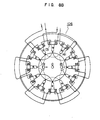
- Fig. 7A shows a construction of the dynamic convergence magnet assembly 100 for the in-line gun type color CRT as shown in Fig. 7B.
- it comprises two four-pole magnets 101 and 102 and two six-pole magnets 103 and 104.
- the four-pole magnets 101 and 102 generate magnetic fields by electromagnetic coils 111 and 121 each having four coil portions as the magnets 21 and 22 of Fig. 4 do.
- the beams R and G are deflected by the magnetic fields in the directions shown by arrows in Fig. 7A like in the case of Fig. 4.
- the correction associated with the indicated direction of correction vector need not always be attained by a single correction coil but it may be attained by a combination of a plurality of correction coils. If the vector can be decomposed, it is desirable that a man-machine characteristic is given a higher priority and the decomposition of the vector and the calculation of the updating quantity for the data memory 230 are done by the CPU 380.
- the correction data stored in the data memory 230 can be copied and stored in the PROM 330.
- the data in the PROM 330 can be recopied to the data memory 230.
- the PROM 330 can be directly used as the data memory 2220. In this case, since the entire adjustment circuit 300 is not necessary, the adjustment circuit 300 may be taken off while leaving only the convergence distortion correction circuit 200.
- Fig. 10 shows a detail of the zone address generator 210 and the guide pattern generator 310.
- the zone address generator 210 comprises a PLL 211, an H (horizontal) zone segment counter 212, an H address counter 213, a sample synchronizer 214, a V (vertical) zone segment counter 215 and a V address counter 216.
- a five-key ADDRESSING switch is used to instruct the shift of the address of the zone to be now subjected to the adjustment of convergence distortion.
- the zone address H4, V90
- the zone address H4, V5
- the zone address H1, V5
- the amounts of shift of the horizontal zone address and the vertical zone address when the respective keys are depressed depend on the selection of the keys of the ZONING switch.
- the CPU 380 calculates the zone address upon each keying operation and sets "1" to the second flag bit of the data memory 230 corresponding to the zone address.
- the guide pattern generator 310 refers to the second flag bit to flicker the guide pattern displayed on the corresponding zone.
- An ENTRY END switch is used to instruct the calculation of interpolation correction data to the CPU 380 in accordance with the programmed algorithm and the writing of the interpolation data in the addresses of the data memory 230 corresponding to the remaining zones.
- a ROM-- ⁇ RAM switch is used to instruct the copying of the data of the PROM 330 to the data memory 230
- a RAM ⁇ ROM switch is used to instruct the copying of the data of the data memory 230 to the PROM 330
- an ON/OFF CONTROL switch is used to selectively validate or invalidate the overall console function.
Landscapes
- Engineering & Computer Science (AREA)
- Multimedia (AREA)
- Signal Processing (AREA)
- Health & Medical Sciences (AREA)
- Biomedical Technology (AREA)
- General Health & Medical Sciences (AREA)
- Video Image Reproduction Devices For Color Tv Systems (AREA)
- Testing, Inspecting, Measuring Of Stereoscopic Televisions And Televisions (AREA)
Description
- The invention refers to a convergence distortion correction method and apparatus as described in the pre-characterizing portion of
claim - Some problems related to a color CRT display will be discussed with reference to Figs. 1 to 5 of the drawings, in which
- Fig. 1 is a block diagram of a color CRT display,
- Fig. 2 shows a structure of the color CRT of Fig. 1,
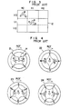
- Fig. 3 illustrates typical examples of convergence distortion,
- Fig. 4 shows an arrangement of static convergence magnets and
- Fig. 5 illustrates the convergence distortion correction when the arrangement of Fig. 4 is used.
- A color CRT display of a television receiver is usually constructed as shown in Fig. 1. On a
CRT 1 are mounted a staticconvergence magnet assembly 2, anauxiliary magnet 8, ahorizontal deflection coil 3 and avertical deflection coil 4. R (red), G (green) and B (blue) signals of aninput video signal 9 are applied through avideo amplifier circuit 6 to three electron guns of theCRT 1. A sync signal is regenerated through separation from theinput video signal 9 and shaping in async separator circuit 7 and applied to the horizontal andvertical deflection coils deflection circuit 5 to effect raster scan. - A portion of the
CRT 1 which relates to the convergence function is shown in Fig. 2. The three electron guns (cathodes) for R, G and B are horizontally arranged at atube neck portion 11 andelectron beams 13 emitted therefrom are deflected by thehorizontal deflection coil 3 and produce light spots on adisplay screen 12. - The R, G and B electron beams should coincide so that the coincident light spot on the
display screen 12 is white when the beams are of equal intensity. In actual, however, the light spots do not coincide but a convergence distortion in the order of several millimeters is included because of mechanical tolerance and a distortion of deflection magnetic fields. The same is true for the vertical convergence. Typical examples of the convergence distortion are shown in Fig. 3 which is a front view of thedisplay screen 12. In Fig. 3, thedisplay screen 12 is divided into nine zones. The degree of convergence distortion differs from zone to zone. - In the prior art, in order to correct the convergence distortion, the static
convergence magnet assembly 2 is coaxially arranged as shown in Fig. 2, which comprises a first four-pole magnet 21, a second four-pole magnet 22, a first six-pole magnet 23 and a second six-pole magnet 24 (see Fig. 4). As shown in Fig. 4, those magnets deflect the beams R and B other than the central beam G in the directions shown by solid line arrows, respectively, by magnetic lines of force H generated thereby. Those four magnets are rotatable around the beams as shown by arcuate broken line arrows ROT so that the deflection directions of the beams R and B may be changed as shown by broken line arrows of Fig. 4 by the rotation of the magnets. Accordingly, the convergence distortion can be corrected by appropriately setting the rotation angles of the magnets. - Fig. 5 shows the correction of the convergence distortion in a central display zone (H1, V1) of Fig. 3 by the static
convergence magnet assembly 2. In the central display zone (H1, V1), the R, B and G light spots coincide, but in the upper left display zone (H0, VO), the R, G and B light spots do not coincide because of the initial convergence distortion as shown in Fig. 3. In order to compensate a difference between the convergence distortions of different display zones, theauxiliary magnet 8 is arranged around thedeflection coils - The above static convergence method has been widely adopted in color CRTs having an in-line arrangement of electron guns. In color CRTs having a delta arrangement of electron guns, a dynamic convergence method has been usually adopted.
- In the typical dynamic convergence method, a dynamic convergence magnet assembly having three radial convergence coils for radially shifting the R, B and G beams and a lateral convergence coil for laterally shifting the B beam is provided. Normally, a dynamic convergence signal is produced by appropriately converting a horizontal deflection output signal and a vertical deflection output signal from the deflection circuits to supply a correction current to the coils. Since the convergence distortion principally is proportional to square of a deflection distance, the dynamic convergence signal can be calculated based on a parabolic curve. In actual, however, the convergence distortion cannot be corrected by a simple parabolic curve and a long time is required to correct the convergence distortion.
- Apart from the analog dynamic convergence distortion correction techniques described above, a digital correction technique to achieve more accurate convergence distortion correction is disclosed in U.S. Patent No. 4,203,051. The correction technique disclosed therein relates to a color CRT having a delta electron gun assembly and a dynamic convergence magnet assembly which comprises convergence coils. The CRT display screen is divided into a plurality of zones and digital correction factor signals for the respective zones are stored in a digital memory.
- When a zone is scanned, the related correction factor signal is applied to the convergence coils. In the example disclosed therein, the display screen is divided into 8 x 8 = 64 zones.
- The content of the memory can be modified by an operator through a CRT display terminal. To this end, the display terminal has a plurality of registers and an address decoder which indicates a zone address of a zone which is selected by the operator for modification and sends it to a control logic. When the control logic receives the zone address from the address decoder, it causes R, B and G grids to be displayed on the corresponding zone and fetches the data of the corresponding zone address from the memory and loads it in the registers. The display terminal further has a set of four-way toggle keys for shifting the displayed R and G grids upwardly, downwardly, leftwardly and rightwardly to align those grids with each other, and another set of four-way toggle keys for shifting the aligned R/G or yellow grid and the B grid upwardly, downwardly, leftwardly and rightwardly. Those keys are connected to the registers. The contents of the registers are modified depending on the manipulation of the toggle keys in the course of the correction to finally align the yellow grid with the B grid to obtain a desired correction, and the data thus modified are retransferred to the memory through the control logic and stored therein.
- The correction factor signals are derived by the operator as described above for each zone separately, which is a long and tedious process.
- US-A-4 203 054 discloses to display test or guide pattern on a number of specified points less than the number of zones into which the display screen is divided, and to carry out the adjustments of convergence distortion for only the specified points.
- However, special connections to the CRT for entering the data derived from the operator's adjustment activities are necessary, and not all CRT's could be adjusted in this manner.
- It is the object of the present invention to provide a convergence correction method and apparatus which are universally usable in all types of color CRT's.
- This object is solved by the method given by the features of
claim 1 and by the apparatus described inclaim 9 in that flags are set to specified zone addresses and guide patterns are displayed on the selected or specified zone having the associated flags. The subject of the invention is applicable to any type of a color CRT, and the convergence distortion is efficiently corrected. The input signal necessary for the convergence distortion correction is the same video signal as that in a conventional color monitor, thus, the dynamic convergence is attained without modifying the interface of the main unit. - Preferred embodiments of the invention are described in
sub-claims 2 to 8 and 10 to 17. - The embodiment according to one of
claims 16 and 17 has the additional advantage that missynchronization can be prevented and that it is compatible with a conventional CRT having no convergence distortion correction. - Some embodiments of the invention are described in conjunction with Figs. 6 to 19 of the drawings, in which
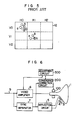
- Fig 6 shows a block diagram of one embodiment of a convergence distortion correction apparatus in accordance with the present invention;
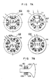
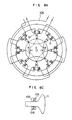
- Figs. 7A and 7B and Figs. 8A, 8B and 8C show dynamic convergence magnet assemblies suitable for use in the present invention;
- Fig. 9 shows a configuration of a convergence distortion correction circuit and an adjustment circuit of the apparatus shown in Fig. 6;
- Fig. 10 shows a detail of a zone address generator and a guide pattern generator shown in Fig. 9;
- Figs. 11 and 12 show waveforms related to the zone address generator in horizontal and vertical zone addresses;
- Fig. 13 shows a correspondence between the horizontal and vertical addresses and a display screen;
- Fig. 14 shows operational waveforms of the guide pattern generator;
- Fig. 15 illustrates an example of display of guide patterns;
- Fig. 16 shows a console shown in Fig. 9;
- Fig. 17 shows a block diagram of another embodiment of the convergence distortion correction apparatus of the present invention;
- Fig. 18 shows a sync regenerator circuit shown in Fig. 17; and
- Fig. 19 shows a chart for explaining advantages of the embodiment of Fig. 17.
- Fig. 6 shows a schematic block diagram of one embodiment of the convergence distortion correction apparatus of the present invention. It differs from Fig. 1 in that a dynamic
convergence magnet assembly 100 instead of the static convergence magnet assembly is used to correct the convergence distortion, that a convergencedistortion correction circuit 200 is provided to supply a correction signal (current correction) to themagnet assembly 100 in synchronism with beam scan, that an output of async separator circuit 7 which produces a sync signal for adeflection circuit 5 is supplied to thecorrection circuit 200, and that anadjustment circuit 300 for supplying a correction data to thecorrection circuit 200 is provided. In actual use of acolor CRT 1, theadjustment circuit 300 is independent. - The
magnet assembly 100 is first explained. While the present invention is applicable to any type of color CRT, a color CRT having an in-line electron gun assembly is specifically explained in the following description. - Fig. 7A shows a construction of the dynamic
convergence magnet assembly 100 for the in-line gun type color CRT as shown in Fig. 7B. In the illustrated example, it comprises two four-pole magnets 101 and 102 and two six-pole magnets pole magnets 101 and 102 generate magnetic fields byelectromagnetic coils 111 and 121 each having four coil portions as themagnets pole magnets electromagnetic coils magnets - Figs. 8A and 8B show another construction of a dynamic
convergence magnet assembly 100 shown in Fig. 8C. In this example, only two magnets are used. Amagnet 105 has the four-pole magnets 101 and 102 shown in Fig. 7B assembled on a common core to form an eight- pole structure having theelectromagnetic coils 111 and 121 arranged alternately, and amagnet 106 has the six-pole magnets electromagnetic coils magnet 105 provides a combined beam deflection of the beam deflections by themagnets 101 and 102 of Figs. 7B and themagnet 106 provides a combined beam deflection of the beam deflections by themagnets electromagnetic coils - The magnet assemblies shown in Figs. 7 and 8 are disclosed in Japanese Laid-Open Patent Application No. 51-71723 laid open on June 21, 1976 (corresponding to Dutch Patent Application No. 7414845 filed on November 14, 1974).
- Referring to Fig. 9, the convergence
distortion correction circuit 200 and theadjustment circuit 300 shown in Fig. 6 are now explained. The convergencedistortion correction circuit 200 comprises azone address generator 210, anaddress selector 220, a digitalcorrection data memory 230 and a digital-to-analog (D/A)converter circuit 210. Thezone address generator 210 receives a sync signal (horizontal and vertical sync signals) from thesync separator circuit 7 and generates addresses for reading out the correction data for the respective zones of the display screen stored in thedata memory 230 in accordance with the electron beam scan. Theaddress selector 220 selectively supplies to thememory 230 the address generated by thezone address generator 210 or the address generated by theadjustment circuit 300. Thedata memory 230 stores therein the correction data necessary to correct the convergence distortion of the CRT. The D/A converter circuit 240 converts the correction data read from thedata memory 230 to an analog signal to supply it to the dynamicconvergence magnet assembly 100 as an exciting current. - On the other hand, the
adjustment circuit 300 comprises aguide pattern generator 310, aconsole 320, agate 350, an effectivedisplay area discriminator 360 and a processing unit (CPU) 380. Theguide pattern generator 310 receives zone information from the convergencedistortion correction circuit 200 and supplies, a signal for displaying a guide pattern on the display screen, to avideo amplifier circuit 6. Theconsole 320 supplies the correction data to thedata memory 230 through theCPU 380 while specifying an address for storing the correction data to thedata memory 230. Theadjustment circuit 300 may include a programmable read-only memory (PROM) 330 for storing a copy of the data stored in thedata memory 230 and aPROM writer 340 for writing the data in thePROM 330 under the instruction from theCPU 380. Thegate 350 selects the read-in of the content of thedata memory 230 to theadjustment circuit 300 or the read-out of the data of theadjustment circuit 300 to thedata memory 230. The effectivedisplay area discriminator 360 receives through the video amplifier circuit 6 a video information signal generated from a display controller (not shown) for displaying any video information over the entire CRT display screen. For example, when the display screen is wholly displayed with white, thediscriminator 360 receives at least one line of video signal components corresponding to R, G and B. When the screen is displayed with red, thediscriminator 360 receives the video signal corresponding to R. The video signal is controlled to generate only at timing when the electron beam scans the effective display area of the CRT screen. By receiving such a video information signal, thediscriminator 360 determines the presence or absence of the video signal in the respective zones and, if it is present, stores the information in flag bit fields of thedata memory 230 at the associated addresses. TheCPU 380 decodes an instruction from theconsole 320 and controls the operations of the respective units in accordance with a programmed control sequence to adjust the convergence distortion. - In the configuration shown in Fig. 9, the operation in the actual use of the CRT after the correction data has been written in the
data memory 230 is explained. - The
zone address generator 210 receives the sync signal from thesync separator circuit 7 and generates a zone address, which is currently scanned by the electron beam, of the display screen which are divided into a plurality of horizontal and vertical matric zones. During this operation, theaddress selector 220 is set to a position to transmit the zone address from thezone address generator 210 to thedata memory 230 so that the correction data at the zone address corresponding to the scanning beam position is read from thedata memory 230 and the correction data is converted to a current signal by the D/A converter circuit 240 to excite the dynamicconvergence magnet assembly 100. - A method for writing the correction data to minimize the convergence distortions at the respective zones of the display screen to the
data memory 230, that is, a method for adjusting the convergence distortion is not explained. - For the adjustment, it is necessary to first display an appropriate test pattern (guide pattern) for the adjustment on the display screen and it is desirable that the number of zones for which the adjustment of convergence distortion is to be made is as small as possible. However, in the actual use of the CRT, the number of zones into which the display screen is divided cannot be reduced because if the number of zones is small the correction data significantly changes from zone to zone and the convergence distortion at the boundary of the zones is conspicious. This trend is remarkable particularly in the vertical direction. Accordingly, it is desirable to obtain the correction data while limiting the number of zones to be subjected to the adjustment of convergence distortion to an extent which allows graspe of the trend of the overall convergence distortion of the display screen, and correction data for the remaining zones are interpolated by means of the correction data based on the adjustment. To this end, it is necessary to discriminate the zones to be subjected to the adjustment and the other zones. Based on the background described above, the characteristic configuration of Fig. 9 and the related adjustment steps are explained below.
- In the
data memory 230, a two-bit flag bit field is associated with each data storage field for storing convergence distortion correction data. Before starting the adjustment steps, the addresses of zones within an effective display of the display . screen are determined by one of the flag bits (first flag bit). To this end, the first flag bits at all of the addresses are initially reset to "0" by theadjustment circuit 300 through theaddress selector 220 and thegate 350. The effectivedisplay area discriminator 360 receives through thevideo amplifier circuit 6 the video information signal from the display controller (not shown), while the addresses are scanned by thezone address generator 210, so that flags are set to the first flag bits through the effectivedisplay area discriminator 360, which responds to a signal level to cause "1" to be set when the video signal is present and "0" to be set when the video signal is absent or blanking. Since the video signal is distributed on the entire display screen, the zone addresses in the effective display area of the display screen can be identified by reading out the first flag bits. As the zone address areas corresponding to the display screen are thus determined, the addresses of the zones which are 'to be preferentially subjected to the adjustment are selected in accordance with an algorithm stored in theCPU 380 with a higher priority being put to corners, and "1"'s (flags A) are set to the first flag bits of thecorrection data memory 230 by theadjustment circuit 300. Since the first flag bits used to identify the effective display area of the display screen are not necessary in this stage, the first flag bits are used again. - As the addresses of the zones to be subjected to the adjustment are determined, the
data memory 230 is again scanned by the output of thezone address generator 210, and theguide pattern generator 310 refers to the first flag bits of thedata memory 230 and the phase of thezone address generator 210 to generate guide pattern signals (to be described later) for only the zones to be subjected to the adjustment. The guide pattern signals are sent to thevideo amplifier circuit 6. The guide pattern signal may have a form which facilitates the adjustment of convergence distortion. The first flag bits of thedata memory 230 are also used as means for limiting the address shift when an address shift instruction is issued by theconsole 320 and identification means in producing the interpolation data. - It is desirable that the guide patterns displayed on the CRT are distinguished from each other in accordance with the sequence of adjustment by the operator. To this end, the other flag bits (second flag bits) of the
data memory 230 are utilized. TheCPU 380 sets a flag B to only one zone address in response to the address shift instruction from theconsole 320. Theguide pattern generator 310 refers to the flag and supplies to the corresponding zone a guide pattern of a different type from those of other zones. As an example, the guide pattern displayed on the corresponding zone is flickered. - When the correction data is to be written in the
data memory 230, it is efficient to indicate the directions of correction vectors for adjustment of convergence distortion on the display screen by a plurality of keys provided on a control panel of theconsole 320 and to cause theCPU 380 to calculate correction data for the indicated direction upon each keying operation, thereby updating the content of thedata memory 230. For example, a program is prepared which causes theCPU 380 to calculate correction data effecting the beam shift or correction of 0.01 mm on the CRT screen by one keying operation (0.1 mm if ten keying operations). For that purpose, it is required that theCPU 380 counts the number of keying operations with respect to each key and the program performs the operation of (the count number) X (a unit vector quantity). The correction associated with the indicated direction of correction vector need not always be attained by a single correction coil but it may be attained by a combination of a plurality of correction coils. If the vector can be decomposed, it is desirable that a man-machine characteristic is given a higher priority and the decomposition of the vector and the calculation of the updating quantity for thedata memory 230 are done by theCPU 380. - When the adjustment of convergence distortions in the zones on which the guide patterns are displayed have been completed or correction data based on the result of adjustment have been written in the
data memory 230 at the addresses corresponding to those zones, these correction data are used by theCPU 380 to produce correction data for the remaining zones in accordance with the programmed interpolation algorithm based on the correction data at the corresponding addresses. If the zones to be subjected to the adjustment of conversion distortion are relatively finely distributed, a low class interpolation algorithm such as linear approximation in two horizontal lines and two vertical lines can be used. For zones out of the effective display area but adjacent to the zones in the effective display area must be provided data interpolated from the data for the zones in the effective display area in order to prevent the affect to the zones in the effective display area. - In this manner, the correction of convergence distortions of the all zones is completed. The correction data stored in the
data memory 230 can be copied and stored in thePROM 330. Thus, if the content of thedata memory 230 is destroyed by the power-off, the data in thePROM 330 can be recopied to thedata memory 230. When thePROM 230 and thedata memory 230 are pin-compatible and packaged by sockets, thePROM 330 can be directly used as the data memory 2220. In this case, since theentire adjustment circuit 300 is not necessary, theadjustment circuit 300 may be taken off while leaving only the convergencedistortion correction circuit 200. - Fig. 10 shows a detail of the
zone address generator 210 and theguide pattern generator 310. Thezone address generator 210 comprises aPLL 211, an H (horizontal)zone segment counter 212, anH address counter 213, asample synchronizer 214, a V (vertical)zone segment counter 215 and aV address counter 216. - The
PLL 211 produces a multiplication-of-21oscillation frequency from a horizontal sync signal produced from thesync separator circuit 7 to cause the Hzone segment counter 212 and the H address counter 213 to complete their cycles during the sync period. The frequency is synchronized with the horizontal sync signal for each cycle. The Hzone segment counter 212 detects a midpoint of one horizontal zone, and the H address counter 213 sets the number of horizontal zone segments to eight and specifies an address of the horizontal zone addresses. TheH address counter 213 includes three stages of shift registers for representing the horizontal zone address (HA) with threebits 2° to 22 (see Fig. 11). The Vzone segment counter 215 sets one of the vertical zone segments by a unit of three rasters and theV address counter 216 generates a vertical segment address. The Vzone segment counter 215 and the V address counter 216 are reset when thesample synchronizer 214 detects a leading edge of the vertical sync signal from thesync separator circuit 7 and cyclically generate the vertical zone addresses in synchronism with the vertical sync signal. Figs. 11 and 12 show waveforms related to thezone address generator 210. In Fig. 12, the total number of rasters in the vertical direction is 529, and the V address counter 216 cycles the address from 0 to 176. Fig. 13 shows a correspondence between the horizontal zone addresses (HA) and the vertical zone addresses (VA), and the display screen. In the horizontal direction, HAO of the addresses HAO to HA7 is in a flyback erase region, and in the vertical direction, VAO to VA3 and a portion of VA4 of the addresses VAO to VA176 are in the flyback erase region, and hence they are not displayed on the display screen. - In the present embodiment, the zones are defined by a unit of eight horizontal segments and three vertical rasters although they are not restrictive.
- Referring back to Fig. 10, the
guide pattern generator 310 comprises adecoder 311, adifferentiator 312, aflicker oscillator 313 andgates 314 to 316. Thedecoder 311, thedifferentiator 312 and thegate 314 detect the midpoint of the zone based on the outputs of the Vzone segment counter 215 and the Hzone segment counter 212 to produce a pulse, which is applied to a first input terminal of the ANDgate 316. To a second input terminal of the ANDgate 316 is applied the first flag bit (flag A) of thedata memory 230. An output of theNAND gate 315 to which an output of theflicker oscillator 313 and the second flag bit (flag B) of thedata memory 230 are applied is applied to an inverted input terminal of the ANDgate 316. Accordingly, the ANDgate 316 produces an output pulse (guide pattern pulse) when the flag A is present, and the guide pattern pulse is flickered when the flag B is present. These pulses are supplied to thevideo amplifier circuit 6. - Fig. 14 shows operational waveforms of the
guide pattern generator 310 and Fig. 15 shows an example of display of the guide patterns on the display screen. In the example of Fig. 15, the guide patterns are displayed in the zones (H1, V5), (H4, V5), (H7, V5), (H1, V90), (H4, V90), (H7, V90), (H1, V175), (H4, V175) and (H7, V175), and the guide pattern in the zone (H4, V90) is flickered. - Fig. 16 shows an example of a control panel of the
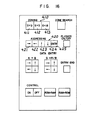
console 320 by functional unit. - A ZONE SEARCH switch is used to instruct the determination of the effective display area of the display screen. The first flag bits of the
data memory 230 at the addresses corresponding to the zone addresses in the effective display area are set to "1" by the effectivedisplay area discriminator 360. - A three-key ZONING switch is used to select the number of the zones to be subjected to the adjustment of convergence distortion. Three zoning levels are provided in the illustration. In the example shown in FIG. 15, 3 x 3 zones are included. By selecting any one of the keys of the ZONING switch, "1"'s are written to the first flag bits of the
data memory 230 corresponding to the addresses of the selected zones. Theguide pattern generator 310 refers to the fi rst flag bits to generate the predetermined guide pattern signals to be displayed. - A five-key ADDRESSING switch is used to instruct the shift of the address of the zone to be now subjected to the adjustment of convergence distortion. Referring to Fig. 15, when a key CNTR is first depressed, the zone address (H4, V90) is selected, and when a vertical up key is then depressed, the zone address (H4, V5) is selected, and when a horizontal left key is then depressed, the zone address (H1, V5) is selected. The amounts of shift of the horizontal zone address and the vertical zone address when the respective keys are depressed depend on the selection of the keys of the ZONING switch. The
CPU 380 calculates the zone address upon each keying operation and sets "1" to the second flag bit of thedata memory 230 corresponding to the zone address. Theguide pattern generator 310 refers to the second flag bit to flicker the guide pattern displayed on the corresponding zone. - A FLICKER ON/OFF switch is used to stop the flicker of the guide pattern as required. The flicker stop function is not specifically illustrated because it can be readily implemented by those skilled in the art.
- An eight-key DATA ENTRY switch is used to indicate the directions of correction vectors for the adjustment of convergence distortion and to update the content of the
data memory 230. The switch comprises an R B key set and a G→ R/B key set. When one of the keys of the ADDRESSING switch is depressed, the guide pattern displayed on the corresponding zone is flickered. At this moment, no data has been written in the corresponding address of thedata memory 230. When the guide pattern does not exhibit a white spot, the operator manipulates right, left, up and down keys (the directions being deflection directions of the R beam with reference to the B beam) of the R B key set until the R beam and the B beam coincide to produce a yellow spot. When the yellow spot is produced, the operator then manipulates right, left, up and down keys (the directions being deflection directions of the G beam with reference to the yellow spot) of the G→ R/B key set until the yellow spot and the G beam coincide to produce a white spot. For each keying operation, theCPU 380 operates to calculate correction data in accordance with a predetermined program so that the content of thedata memory 230 for each keying operation is updated and a current is supplied to related convergence coils through the D/A converter circuit 240 based on the updated content of thedata memory 230. In this manner, final correction data is written or established in the address of thedata memory 230 corresponding to the zone in question. The ADDRESSING switch is then manipulated to shift the zone address and similar operation is carried out with respect to the new zone. - More especially, correction data obtained through the manipulation of the R - B key set is associated with the
coils 111 and 121 shown in Fig. 7 or 8 while correction data obtained through the manipulation of the G-> R/B key set is associated with thecoils coil 121, the left and right keys in the G → R/B key set to thecoil 131, and the up and down keys in the G → R/B key set to thecoil 141. As has been described earlier, theCPU 380 counts the number of keying operations with respect to each key and performs the operation of (the count number) x (a unit vector quantity). - Though the above example has employed the adjustment operation which includes a first step of coinciding the R beam with the B beam and a second step of coinciding the G beam with the R/B spot, there may be used a method which includes a first step of coinciding the R (or B) beam with the G beam and a second step of coinciding B (or R) beam with the G beam. This method may be convenient for the operator since both the steps are made with reference to the G beam. For that purpose, the DATA ENTRY switch may include an R → G four-way key set and a B → G four-way key set. In this case, it will be understood that each key should be related to not a single coil but two or more coils of the
magnet assembly 100. Unit correction vector quantities are associated with the respective directing keys. A program is required which causes to theCPU 380 to perform the operation of (the count number of keying operations) x (the associated unit vector quantity) and to decompose the resultant vector data into correction data components for the related coils. This method can enhance the workability of adjustment since the number of keying operations will be decreased. - An ENTRY END switch is used to instruct the calculation of interpolation correction data to the
CPU 380 in accordance with the programmed algorithm and the writing of the interpolation data in the addresses of thedata memory 230 corresponding to the remaining zones. A ROM--→ RAM switch is used to instruct the copying of the data of thePROM 330 to thedata memory 230, a RAM → ROM switch is used to instruct the copying of the data of thedata memory 230 to thePROM 330, and an ON/OFF CONTROL switch is used to selectively validate or invalidate the overall console function. - As described hereinabove, according to the present invention, the convergence distortion of the color CRT is efficiently corrected. For example, when the data bit width of the
correction data memory 230 is five-bit width (four bits plus one sign bit), a correction precision is as small as 1/16 of the uncorrected maximum convergence distortion. Thus, it can readily attain an appreciable limit of the convergence distortion (approximately 0.1 mm).. - According to the present invention, the input signal necessary for the correction is the same video signal as that in the conventional color monitor and the dynamic convergence is attained without modifying the interface of the main unit. Accordingly, a high quality color monitor which is corrected for the convergence distortion can be employed.
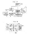
- Fig. 17 shows a configuration of a further embodiment of the present invention. The feature of the present embodiment, to compare with the embodiment of Fig. 6, resides in that the sync signal to the convergence
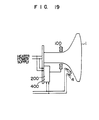
distortion correction circuit 200 is regenerated by async regenerator circuit 400 from drive signals forthe horizontal and vertical deflection coils 3 and 4. Thesync regenerator circuit 400 may be constructed by insulatingtransformers 401 andcomparators 402 as shown in Fig. 18. The present embodiment can prevent missynchronization which may take place when the sync signal is regenerated by the sync separator circuit. - A constructual advantage of the present embodiment is apparent from a packaging diagram shown in Fig. 19. The dynamic
convergence magnet assembly 100, the convergencedistortion correction circuit 200 and thesync regenerator circuit 400, which are minimum functional unit necessary for the correction of the convergence distortion, are integrally mounted at a neck portion of theCRT 1 with the horizontal andvertical coils distortion correction circuit 200 and thesync regenerator circuit 400 is shared with a heater voltage of theCRT 1. As a result a compatibility with the conventional CRT having no convergence distortion correction function is attained and a restriction in applying the present invention is materially relieved. - While the present invention has been described with reference to specific embodiments, it should be understood by those skilled in the art that various modifications can be made. For example, while the flag bit field of the
data memory 230 has two bits in the illustrated embodiment, it may have only one bit (first flag bit) when it is not desired to flicker the guide pattern. While the flags are written into the first flag bits by the effectivedisplay area discriminator 360 prior to the adjustment of convergence, distortion, this step is not necessary if the zones to be subjected to the adjustment of convergence distortion are appropriately selected. While the present invention has been described in connection with the specific dynamic convergence magnet assembly and the in-line electron guns, it should be understood that the present invention is applicable to a color CRT having other types of electron guns and/or dynamic convergence magnet assembly.
Claims (17)
characterized in that between said second and third steps said method comprises:
characterized in that said digital memory (230) has flag bit fields associated with the data storage fields, that said adjustment circuit (300) includes an operator-manipulated address specifying section (320) for supplying addresses of the selected zones of said CRT (1) to be subjected to the adjustment of convergence distortion to a second input terminal of said address selector (220) to set flags to the flag bit fields of said digital memory (230) at the corresponding addresses, and that said guide pattern generator (310) receives said flags from said digital memory (230) as well as the zone addresses from said address generator (210) so that the guide patterns are displayed on the selected zones having the zone addresses, which correspond to the addresses of said digital memory (230) having said flags.
Applications Claiming Priority (2)
| Application Number | Priority Date | Filing Date | Title |
|---|---|---|---|
| JP56098988A JPS57212492A (en) | 1981-06-24 | 1981-06-24 | Color diviation corrector for color braun tube |
| JP98988/81 | 1981-06-24 |
Publications (3)
| Publication Number | Publication Date |
|---|---|
| EP0068420A2 EP0068420A2 (en) | 1983-01-05 |
| EP0068420A3 EP0068420A3 (en) | 1984-09-26 |
| EP0068420B1 true EP0068420B1 (en) | 1987-11-11 |
Family
ID=14234370
Family Applications (1)
| Application Number | Title | Priority Date | Filing Date |
|---|---|---|---|
| EP82105486A Expired EP0068420B1 (en) | 1981-06-24 | 1982-06-22 | Convergence distortion correction method and apparatus for color cathode-ray tube |
Country Status (4)
| Country | Link |
|---|---|
| US (1) | US4401922A (en) |
| EP (1) | EP0068420B1 (en) |
| JP (1) | JPS57212492A (en) |
| DE (1) | DE3277679D1 (en) |
Families Citing this family (30)
| Publication number | Priority date | Publication date | Assignee | Title |
|---|---|---|---|---|
| JPS59167194A (en) * | 1983-03-11 | 1984-09-20 | Hitachi Ltd | Registration correcting circuit of color television camera |
| US4633143A (en) * | 1983-05-31 | 1986-12-30 | Sperry Corporation | Convergence correction apparatus for delta-gun color cathode ray tube displays |
| DE3473201D1 (en) * | 1984-05-23 | 1988-09-08 | Itt Ind Gmbh Deutsche | Method and circuit arrangement for digital deflection correction of television picture tubes |
| JPS6178294A (en) * | 1984-09-25 | 1986-04-21 | Sony Corp | Correcting device for digital convergence |
| US4620136A (en) * | 1984-11-29 | 1986-10-28 | Rca Corporation | Digital vertical beam landing correction circuit |
| JPS61163791A (en) * | 1985-01-16 | 1986-07-24 | Sony Corp | Device for correcting dynamic landing |
| FR2579051B1 (en) * | 1985-03-15 | 1988-06-24 | Loire Electronique | CONVERGENCE ADJUSTING DEVICE FOR VIDEO PROJECTOR |
| US4673847A (en) * | 1985-04-12 | 1987-06-16 | Hazeltine Corporation | Color monitor with improved digital convergence |
| US4680510A (en) * | 1985-04-12 | 1987-07-14 | Hazeltine Corporation | Color monitor with improved synchronization |
| JPS61280191A (en) * | 1985-06-04 | 1986-12-10 | Mitsubishi Electric Corp | Convergence subadjusting device |
| JPS61281791A (en) * | 1985-06-07 | 1986-12-12 | Sony Corp | Digital convergence device |
| US4757239A (en) * | 1985-10-18 | 1988-07-12 | Hilliard-Lyons Patent Management, Inc. | CRT display system with automatic alignment employing personality memory |
| US4687973A (en) * | 1986-07-09 | 1987-08-18 | Electronic Image Systems, Inc. | Digital waveform generator |
| JP2542592B2 (en) * | 1986-12-17 | 1996-10-09 | 株式会社東芝 | Color picture tube device |
| JP2608908B2 (en) * | 1988-01-28 | 1997-05-14 | 株式会社日立製作所 | Digital convergence correction device |
| JP3035912B2 (en) * | 1988-10-14 | 2000-04-24 | ソニー株式会社 | Image display correction waveform data generator |
| US4871948A (en) * | 1988-11-08 | 1989-10-03 | Honeywell Inc. | Memory mapped deflection correction system |
| US5161002A (en) * | 1989-08-23 | 1992-11-03 | Thomson Consumer Electronics, Inc. | Convergence control system for multiple vertical formats |
| SG119127A1 (en) * | 1989-08-23 | 2006-02-27 | Thomson Consumer Electronics | Apparatus and method for displaying letterbox pictures |
| US4977355A (en) * | 1989-08-23 | 1990-12-11 | Rca Licensing Corportion | Convergence control system |
| US5041764A (en) * | 1990-10-22 | 1991-08-20 | Zenith Electronics Corporation | Horizontal misconvergence correction system for color video display |
| EP0516229B1 (en) * | 1991-05-31 | 1996-01-03 | Koninklijke Philips Electronics N.V. | Display tube including a convergence correction device |
| EP0529570B1 (en) * | 1991-08-30 | 1997-10-29 | Hitachi, Ltd. | Digital image correction device |
| US5739870A (en) * | 1996-03-11 | 1998-04-14 | Display Laboratories, Inc. | Math engine for generating font gradients |
| JPH10126799A (en) * | 1996-10-23 | 1998-05-15 | Nec Corp | Convergence adjusting method and convergence adjusting circuit |
| US6281950B1 (en) | 1997-06-16 | 2001-08-28 | Display Laboratories, Inc. | High speed digital zone control |
| JP2983509B2 (en) * | 1998-02-10 | 1999-11-29 | 日本放送協会 | Method and apparatus for detecting flicker of television image |
| KR20010101223A (en) * | 1999-10-15 | 2001-11-14 | 요트.게.아. 롤페즈 | Color display device with deflection means and a co-operating pair of means for influencing the distance between electron beams |
| KR100393559B1 (en) * | 2000-09-30 | 2003-08-02 | 삼성전기주식회사 | Control method for digital dynamic convergence and system for the same |
| US6404146B1 (en) | 2001-01-31 | 2002-06-11 | Innovision Corporation | Method and system for providing two-dimensional color convergence correction |
Family Cites Families (7)
| Publication number | Priority date | Publication date | Assignee | Title |
|---|---|---|---|---|
| US3943279A (en) * | 1974-09-23 | 1976-03-09 | Aeronutronic Ford Corporation | Digital convergence of multiple image projectors |
| NL7414845A (en) * | 1974-11-14 | 1976-05-18 | Philips Nv | DEVICE FOR DISPLAYING COLOR TV IMAGES. |
| GB1517119A (en) * | 1976-12-22 | 1978-07-12 | Ibm | Cathode ray tube control apparatus |
| GB1586201A (en) * | 1977-09-15 | 1981-03-18 | Ibm | Methods of generating correction factor signals for cathode ray tubes |
| DE2805691C3 (en) * | 1978-02-10 | 1983-11-03 | Siemens AG, 1000 Berlin und 8000 München | Digital control unit in a color television receiver to control the deflection output stages |
| JPS55163988A (en) * | 1979-06-07 | 1980-12-20 | Nippon Hoso Kyokai <Nhk> | Digital convergence unit |
| JPS56777A (en) * | 1979-06-18 | 1981-01-07 | Chuo Musen Kk | Corrector for digital convergence |
-
1981
- 1981-06-24 JP JP56098988A patent/JPS57212492A/en active Granted
-
1982
- 1982-06-22 EP EP82105486A patent/EP0068420B1/en not_active Expired
- 1982-06-22 DE DE8282105486T patent/DE3277679D1/en not_active Expired
- 1982-06-24 US US06/391,916 patent/US4401922A/en not_active Expired - Lifetime
Also Published As
| Publication number | Publication date |
|---|---|
| JPS57212492A (en) | 1982-12-27 |
| EP0068420A2 (en) | 1983-01-05 |
| US4401922A (en) | 1983-08-30 |
| DE3277679D1 (en) | 1987-12-17 |
| JPS6216076B2 (en) | 1987-04-10 |
| EP0068420A3 (en) | 1984-09-26 |
Similar Documents
| Publication | Publication Date | Title |
|---|---|---|
| US4401922A (en) | Convergence distortion correction method and apparatus for color cathode-ray tube | |
| US4203051A (en) | Cathode ray tube apparatus | |
| US4672275A (en) | Digital process and apparatus for convergence correction having adjustment points and correction portions determined by the adjustment point selected | |
| JPS61281791A (en) | Digital convergence device | |
| US5506481A (en) | Registration error correction device | |
| US6437829B1 (en) | Alignment of cathode ray tube displays using a video graphics controller | |
| WO1998032277A9 (en) | Alignment of cathode ray tube displays using a video graphics controller | |
| US4673847A (en) | Color monitor with improved digital convergence | |
| US5497054A (en) | Automatic digital convergence correcting method and apparatus therefor | |
| US4680510A (en) | Color monitor with improved synchronization | |
| CA2182546A1 (en) | Digital convergence apparatus | |
| JPH0225594B2 (en) | ||
| JPH04216275A (en) | Raster distortion correcting circuit | |
| JPS6013595B2 (en) | Television camera control device | |
| CN1041045C (en) | graphics generator | |
| US5963274A (en) | Vertical/horizontal interpolation device and method in convergence system | |
| EP0271906B1 (en) | Color image display tube apparatus | |
| CA1224561A (en) | Television receiver | |
| EP1245120B1 (en) | Automated convergence in a projection display apparatus | |
| JP3675357B2 (en) | Registration adjustment apparatus and registration adjustment method | |
| EP0198494A2 (en) | Color cathode ray apparatus | |
| JPS60236380A (en) | Focus correcting device of cathode-ray tube | |
| US5644197A (en) | Cathode ray tube display apparatus with rotatable raster | |
| JPH0126234B2 (en) | ||
| JPH0583719A (en) | Digital Dynamics Convergence Device |
Legal Events
| Date | Code | Title | Description |
|---|---|---|---|
| PUAI | Public reference made under article 153(3) epc to a published international application that has entered the european phase |
Free format text: ORIGINAL CODE: 0009012 |
|
| AK | Designated contracting states |
Designated state(s): BE CH DE FR GB IT LI NL SE |
|
| 17P | Request for examination filed |
Effective date: 19830208 |
|
| PUAL | Search report despatched |
Free format text: ORIGINAL CODE: 0009013 |
|
| AK | Designated contracting states |
Designated state(s): BE CH DE FR GB IT LI NL SE |
|
| GRAA | (expected) grant |
Free format text: ORIGINAL CODE: 0009210 |
|
| AK | Designated contracting states |
Kind code of ref document: B1 Designated state(s): BE DE GB IT NL |
|
| REF | Corresponds to: |
Ref document number: 3277679 Country of ref document: DE Date of ref document: 19871217 |
|
| ITF | It: translation for a ep patent filed | ||
| PLBE | No opposition filed within time limit |
Free format text: ORIGINAL CODE: 0009261 |
|
| STAA | Information on the status of an ep patent application or granted ep patent |
Free format text: STATUS: NO OPPOSITION FILED WITHIN TIME LIMIT |
|
| 26N | No opposition filed | ||
| ITTA | It: last paid annual fee | ||
| PGFP | Annual fee paid to national office [announced via postgrant information from national office to epo] |
Ref country code: BE Payment date: 19920417 Year of fee payment: 11 |
|
| PGFP | Annual fee paid to national office [announced via postgrant information from national office to epo] |
Ref country code: GB Payment date: 19920508 Year of fee payment: 11 |
|
| PGFP | Annual fee paid to national office [announced via postgrant information from national office to epo] |
Ref country code: NL Payment date: 19920630 Year of fee payment: 11 |
|
| PGFP | Annual fee paid to national office [announced via postgrant information from national office to epo] |
Ref country code: DE Payment date: 19920828 Year of fee payment: 11 |
|
| PG25 | Lapsed in a contracting state [announced via postgrant information from national office to epo] |
Ref country code: GB Effective date: 19930622 |
|
| PG25 | Lapsed in a contracting state [announced via postgrant information from national office to epo] |
Ref country code: BE Effective date: 19930630 |
|
| BERE | Be: lapsed |
Owner name: HITACHI LTD Effective date: 19930630 |
|
| PG25 | Lapsed in a contracting state [announced via postgrant information from national office to epo] |
Ref country code: NL Effective date: 19940101 |
|
| GBPC | Gb: european patent ceased through non-payment of renewal fee |
Effective date: 19930622 |
|
| NLV4 | Nl: lapsed or anulled due to non-payment of the annual fee | ||
| PG25 | Lapsed in a contracting state [announced via postgrant information from national office to epo] |
Ref country code: DE Effective date: 19940301 |