EP0068082B1 - Process for measuring the out-of-roundness of rotation-symmetrical articles - Google Patents
Process for measuring the out-of-roundness of rotation-symmetrical articles Download PDFInfo
- Publication number
- EP0068082B1 EP0068082B1 EP82102711A EP82102711A EP0068082B1 EP 0068082 B1 EP0068082 B1 EP 0068082B1 EP 82102711 A EP82102711 A EP 82102711A EP 82102711 A EP82102711 A EP 82102711A EP 0068082 B1 EP0068082 B1 EP 0068082B1
- Authority
- EP
- European Patent Office
- Prior art keywords
- rotation
- roundness
- digital computer
- rotational solid
- axis
- Prior art date
- Legal status (The legal status is an assumption and is not a legal conclusion. Google has not performed a legal analysis and makes no representation as to the accuracy of the status listed.)
- Expired
Links
Images
Classifications
-
- G—PHYSICS
- G01—MEASURING; TESTING
- G01B—MEASURING LENGTH, THICKNESS OR SIMILAR LINEAR DIMENSIONS; MEASURING ANGLES; MEASURING AREAS; MEASURING IRREGULARITIES OF SURFACES OR CONTOURS
- G01B7/00—Measuring arrangements characterised by the use of electric or magnetic techniques
- G01B7/28—Measuring arrangements characterised by the use of electric or magnetic techniques for measuring contours or curvatures
- G01B7/282—Measuring arrangements characterised by the use of electric or magnetic techniques for measuring contours or curvatures for measuring roundness
-
- G—PHYSICS
- G01—MEASURING; TESTING
- G01B—MEASURING LENGTH, THICKNESS OR SIMILAR LINEAR DIMENSIONS; MEASURING ANGLES; MEASURING AREAS; MEASURING IRREGULARITIES OF SURFACES OR CONTOURS
- G01B21/00—Measuring arrangements or details thereof, where the measuring technique is not covered by the other groups of this subclass, unspecified or not relevant
- G01B21/20—Measuring arrangements or details thereof, where the measuring technique is not covered by the other groups of this subclass, unspecified or not relevant for measuring contours or curvatures, e.g. determining profile
-
- G—PHYSICS
- G01—MEASURING; TESTING
- G01B—MEASURING LENGTH, THICKNESS OR SIMILAR LINEAR DIMENSIONS; MEASURING ANGLES; MEASURING AREAS; MEASURING IRREGULARITIES OF SURFACES OR CONTOURS
- G01B7/00—Measuring arrangements characterised by the use of electric or magnetic techniques
- G01B7/34—Measuring arrangements characterised by the use of electric or magnetic techniques for measuring roughness or irregularity of surfaces
- G01B7/345—Measuring arrangements characterised by the use of electric or magnetic techniques for measuring roughness or irregularity of surfaces for measuring evenness
Definitions
- the invention is based on a method for determining the roundness deviations of a rotating body according to the preamble of claim 1 in accordance with DE-A-24 25 226.
- DE-A-24 59 678 describes a device for measuring the roundness of a workpiece, in which the analog output signal of a detector for sensing the workpiece size, which consists of the sum of a signal caused by eccentricity and a signal caused by rounding errors, is provided once via a device for Absolute value determination and, on the other hand, a low-pass filter and a further device for determining the absolute value are fed to a computing device, at whose output the absolute value of the rounding error appears, which can be displayed in a display device in analog or digital form.
- US-A-3 231 979 describes a method for checking the surface shape of a rotating body by means of an analog length measuring probe. that generates an overall electrical measurement that corresponds to the surface profile and the centering error; in addition, an electrical sinusoidal correction quantity is generated that corresponds to the centering error.
- the total measurement quantity and the correction quantity are fed to a difference-forming measuring instrument for the difference formation.
- DE-A-24 25 226 specifies a method for measuring the surface of a workpiece, in which a sensor is guided across the surface in a traverse in order to supply analog signals which are characteristic of the profile of the surface and which are provided by an analog-digital converter implemented and a Dig i are supplied talrechner. From these digital values and from digital signals, which represent the relative angular position between the sensor and the workpiece, parameters for a reference line are determined, which is centered in the middle of the scanned workpiece and can be related to the roundness deviations of the surface of the workpiece. The calculation of the reference line is based on an equation for an eccentric circle that contains only the first-order eccentricity element.
- the invention has the object of providing a method for determining the round i he tsabweichitch a rotary body of the above-mentioned type indicate which allows with simple means, a highly accurate determination of the roundness deviations of the rotating body even without exact centering with respect to the axis of rotation.
- the advantages achieved by the invention consist in particular in that the rotary body can be arranged relatively strongly eccentrically to the axis of rotation, so that a time-consuming and costly accurate centering is unnecessary. All important data such as the size and angle of the roundness deviations and the eccentricity, elliptical errors, triangular errors as well as further Fourier coefficients of the roundness deviations and the concentricity of several rotating surfaces of a rotating body can be determined by the computer. Furthermore, after a single calibration process with a teaching cylinder, the absolute dimension of the radius of the rotating body can be specified.
- a digital electrical scanning device incrementmental or absolute measuring probe
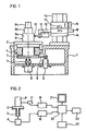
- FIG. 1 a device for measuring the roundness deviations of rotating bodies is shown schematically.
- a rotary table 2 with a spindle 3 is rotatably mounted in a precision bearing 4 in a stationary frame 1.
- the spindle 3 is driven by a belt 5 by a motor 6 fastened in the frame 1.
- the spindle 3 is rigidly connected to an angle measuring device 8 via a coupling 7.
- a rotating body 9 with three rotating surfaces 9a, 9b, 9c is arranged on the surface of the rotary table 2.
- the rotating surfaces 9a. 9b, 9c of the rotating rotary body 9 are scanned according to the invention by the scanning head 10 of a digital scanning device 11 which is carried by an arm 12.
- a vertical column 13 is fastened with a vertical slide 14, which can be adjusted in height by means of an adjusting screw 15.
- a horizontal slide 16 is arranged, which is connected to the arm 12 and can be adjusted horizontally by means of an adjusting screw 17.
- FIG 2 the measuring device according to Figure 1 with the rotary table 2, the spindle 3, the angle measuring device 8, the rotating body 9 and the scanning device 11 is shown in simplified form.
- the digital output signals of the scanning device 11 are fed via an up / down counter 18 and the digital output signals of the angle measuring device 8 via an up / down counter 19 to a digital computer 20 which is connected to a display unit 21 and a printing device 22 and acted upon by an alphanumeric input unit 23 is.
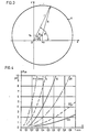
- FIG. 3 shows a circular rotary body K with the radius R, the center A of which is shifted by an eccentricity e with respect to an axis of rotation 0.
- the axis of rotation 0 may be in the origin of a coordinate system y, x, so that the center A of the rotating body K has the coordinates x o , y o .
- the eccentricity e includes the angle ⁇ with the x-axis and the instantaneous beam r includes the angle ⁇ with the x-axis.
- Figure 3 shows the instantaneous beam r as a function of the angle ⁇ from the equation the relationship and after development into a Fourier series
- F 2 F 20 . cos 2 ( ⁇ - a) with the period ⁇ shows an actually circular rotation body K with an eccentric clamping an apparent elliptical error.
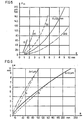
- the size of the maximum elliptical error F 20 is shown as a diagram in FIGS. 4 and 5 as a function of the eccentricity e and the radius R of the rotating body K.
- the dashed lines a and b in FIG. 6 show that the permissible eccentricity e can be roughly applied with R / 10 or R / 20 if ⁇ should remain less than 1 ⁇ m or less than 0.1 ⁇ m. Since the term F 3 and the following terms of the polynomial can be neglected, the instantaneous ray r is a function of the angle ⁇
- the individual measured values M i are regularly distributed over the angle 2 ⁇ .
- 8 n measuring positions are defined by the angle measuring device over the angle 2 ⁇ .
- the number n must be chosen so large that the profile of the rotating surface 9a, 9b, 9c of the rotating body 9 to be tested can be determined with sufficient certainty.
- the number n is limited upwards by the storage capacity of the digital computer 20.
- the number n of measurement positions will be between 200 and 10,000. 200 measured values are to be regarded as a minimum for determining the roundness deviations of the rotating body (9).
- a correction value E is calculated from this the one for calculating the absolute radius R of the rotating body 9 is used.
- the digital computer 20 is used to store the measured values, to eliminate the eccentricity e and the apparent elliptical error F 2 and, if appropriate, the higher-order errors to calculate the roundness deviations and for Fourier analysis of the roundness deviations and, if appropriate, to statistically evaluate a series of roundness measurements; Furthermore, the concentricity of a plurality of rotation surfaces 9a, 9b, 9c of the rotation body 9 or the oblique position of the axis of rotation of the rotation body 9 with respect to the contact surface can be determined.
- the measurement result can be displayed on the printing device 22 in the form of an X-Y recorder or a polar chart recorder or on a display device 21 with a screen in the form of a polar roundness error diagram.
Abstract
Description
Die Erfindung geht von einem Verfahren zur Bestimmung der Rundheitsabweichungen eines Rotationskörpers gemäß dem Oberbegriff des Anspruches 1 entsprechend der DE-A-24 25 226 aus.The invention is based on a method for determining the roundness deviations of a rotating body according to the preamble of
Aus der Druckschrift « Feinwerktechnik und Meßtechnik 87 (1979) 5, Seiten 227-232 ist eine Polarkoordinatenmeßmaschine zur Ermittlung der Polarkoordinaten von Kurvenscheiben mittels einer digitalen Abtasteinrichtung bekannt, bei der ein Digitalrechner die Differenz zwischen vorgegebenen Radiussollwerten und gemessenen Radiusistwerten ermittelt. Die Exzentrizität der Kurvenscheibe bezüglich einer Drehachse wird durch Messen der Lage einer Bezugsbohrung in der Kurvenscheibe auf die Sollkoordinatenwerte umgerechnet oder die Kurvenscheibe wird bezüglich der Drehachse mittels einer x-y-Verstellung zentriert, indem aus den vier Radien der Bezugsbohrung in den x-y-Richtungen die Sollradien in diesen beiden Richtungen ermittelt werden.From the publication "Feinwerktechnik und Meßtechnik 87 (1979) 5, pages 227-232, a polar coordinate measuring machine for determining the polar coordinates of cams by means of a digital scanning device is known, in which a digital computer determines the difference between predetermined radius setpoints and measured radius actual values. The eccentricity of the cam disc with respect to an axis of rotation is converted to the target coordinate values by measuring the position of a reference bore in the cam disc or the cam disc is centered with respect to the axis of rotation by means of an xy adjustment, by using the four radii of the reference bore in the xy directions to determine the target radii in these two directions.
In der DE-A-24 59 678 ist eine Einrichtung zum Messen der Rundheit eines Werkstücks beschrieben, bei der das analoge Ausgangssignal eines Detektors zum Fühlen der WerkstückgröBe, welches aus der Summe eines exzentrizitätsbedingten Signals und eines rundungsfehlerbedingten Signals besteht, einmal über eine Einrichtung zur Absolutwertermittlung und zum anderen über ein Tiefpaßfilter und eine weitere Einrichtung zur Absolutwertermittlung einer Recheneinrichtung zugeleitet wird, an derem Ausgang der Absolutwert des Rundungsfehlers erscheint, der in einer Anzeigeeinrichtung in analoger oder digitaler Form angezeigt werden kann.DE-A-24 59 678 describes a device for measuring the roundness of a workpiece, in which the analog output signal of a detector for sensing the workpiece size, which consists of the sum of a signal caused by eccentricity and a signal caused by rounding errors, is provided once via a device for Absolute value determination and, on the other hand, a low-pass filter and a further device for determining the absolute value are fed to a computing device, at whose output the absolute value of the rounding error appears, which can be displayed in a display device in analog or digital form.
Die US-A-3 231 979 beschreibt ein Verfahren zum Prüfen der Oberflächengestalt eines Rotationskörpers mittels eines analogen Längenmeßtasters. der eine elektrische Gesamtmeßgröße erzeugt, die dem Oberflächenprofil und dem Zentrierfehler entspricht; zusätzlich wird eine elektrische sinusförmige Berichtigungsgröße erzeugt, die dem Zentrierfehler entspricht. Die Gesamtmeßgröße und die BerichtigungsgröBe werden einem differenzbildenen Meßinstrument zur Differenzbildung zugeführt.US-A-3 231 979 describes a method for checking the surface shape of a rotating body by means of an analog length measuring probe. that generates an overall electrical measurement that corresponds to the surface profile and the centering error; in addition, an electrical sinusoidal correction quantity is generated that corresponds to the centering error. The total measurement quantity and the correction quantity are fed to a difference-forming measuring instrument for the difference formation.
In der Zeitschrift « Journal of Physics and Scientlfic Instruments •, Band 9, Nr. 7, Juli 1976, S. 537-544 ist eine Einrichtung zur Ermittlung der Rundheitsabweichungen eines Rotationskörpers beschrieben, dessen Oberflächenprofil von einer analogen Abtasteinrichtung abgetastet wird. Eine Trennung von Spindelfehlern und Profilfehlern wird in Verbindung mit einer Kompensation der Exzentrizität mittels eines Rechners durchgeführt.In the journal "Journal of Physics and Scientlfic Instruments",
In der DE-A-24 25 226 ist ein Verfahren zum Ausmessen der Oberfläche eines Werkstücks angegeben, bei dem ein Fühler in einer Traverse über die Oberfläche geführt wird, um für das Profil der Oberfläche charakteristische Analogsignale zu liefem, die von einem Analog-Digital-Wandler umgesetzt und einem Digitalrechner zugeführt werden. Aus diesen Digitalwerten und aus digitalen Signalen, die die relative Winkellage zwischen dem Fühler und dem Werkstück darstellen, werden Parameter für eine Bezugslinie ermittelt, die in der Mitte des abgetasteten Werkstücks zentriert ist und auf die Rundheitsabweichungen der Oberfläche des Werkstücks bezogen werden können. Bei der Berechnung der Bezugslinie wird von einer Gleichung für einen exzentrischen Kreis ausgegangen, die nur das Exzentrizitätsglied erster Ordnung enthält.DE-A-24 25 226 specifies a method for measuring the surface of a workpiece, in which a sensor is guided across the surface in a traverse in order to supply analog signals which are characteristic of the profile of the surface and which are provided by an analog-digital converter implemented and a Dig i are supplied talrechner. From these digital values and from digital signals, which represent the relative angular position between the sensor and the workpiece, parameters for a reference line are determined, which is centered in the middle of the scanned workpiece and can be related to the roundness deviations of the surface of the workpiece. The calculation of the reference line is based on an equation for an eccentric circle that contains only the first-order eccentricity element.
Bei den Meßeinrichtungen mit analogen meßwertaufnehmern besitzen diese wegen des hohen Auflösungsvermögens zur Ermittlung der Rundheitsabweichungen nur einen begrenzten Meßbereich. Daher muß die Zentrierung des zu prüfenden Werkstücks bezüglich der Drehachse einer MeBspindel möglichst genau sein ; dieser Zentrierungsvorgang ist schwierig, zeit- und kostenaufwendig und erfordert den Einsatz von geschultem Personal.In the case of measuring devices with analog sensors, these have only a limited measuring range due to the high resolution for determining the roundness deviations. The centering of the workpiece to be tested must therefore be as precise as possible with respect to the axis of rotation of a measuring spindle; this centering process is difficult, time-consuming and costly and requires the use of trained personnel.
Der Erfindung liegt die Aufgabe zugrunde, ein Verfahren zur Bestimmung der Rund- heitsabweichungen eines Rotationskörpers der oben genannten Gattung anzugeben, das mit einfachen Mitteln eine hochgenaue Ermittlung der Rundheitsabweichungen des Rotationskörpers auch ohne genaue Zentrierung bezüglich der Drehachse ermöglicht.The invention has the object of providing a method for determining the round i he tsabweichungen a rotary body of the above-mentioned type indicate which allows with simple means, a highly accurate determination of the roundness deviations of the rotating body even without exact centering with respect to the axis of rotation.
Diese Aufgabe wird bei einem Verfahren die eingangs genannten Art erfindungsgemäß durch die kennzeichnenden Merkmale des Anspruchs 1 gelöst.This object is achieved according to the invention in a method of the type mentioned at the outset by the characterizing features of
Die mit der Erfindung erzielten Vorteile bestehen insbesondere darin, daß der Rotationskörper relativ stark exzentrisch zur Drehachse angeordnet sein kann, do daß sich eine Zeit- und kostenaufwendige genaue Zentrierung erübrigt. Alle wichtigen Daten wie Größe und WinkeHage der Rundheitsabweichungen und der Exzentrizität, elliptischer Fehler, Dreiecksfehler sowie weitere FourierKoeffizienten der Rundheitsabweichungen und die Konzentrizität mehrerer Rotationsflächen eines Rotationskörpers können durch den Rechner ermittelt werden. Des weiteren kann nach einem einmaligen Eichvorgang mit einem Lehrzylinder das AbsolutmaB des Radius des Rotationskörpers angegeben werden. Obige Vorteile werden hauptsächlich durch das erfindungsgemäße Vorsehen einer digitalen elektrischen Abtasteinrichtung (inkrementaler oder absoluter Meßtaster) ermöglicht.The advantages achieved by the invention consist in particular in that the rotary body can be arranged relatively strongly eccentrically to the axis of rotation, so that a time-consuming and costly accurate centering is unnecessary. All important data such as the size and angle of the roundness deviations and the eccentricity, elliptical errors, triangular errors as well as further Fourier coefficients of the roundness deviations and the concentricity of several rotating surfaces of a rotating body can be determined by the computer. Furthermore, after a single calibration process with a teaching cylinder, the absolute dimension of the radius of the rotating body can be specified. The above advantages are made possible mainly by the provision according to the invention of a digital electrical scanning device (incremental or absolute measuring probe).
Weitere vorteilhafte Ausgestaltungen des Verfahrens entnimmt man den Unteransprüchen.Further advantageous refinements of the method can be found in the subclaims.
Ausführungsbeispiele der Erfindung werden anhand der Zeichnung näher beschrieben.Embodiments of the invention are described in more detail with reference to the drawing.
Es zeigen
Figur 1 eine schematische Darstellung einer Rundheitsmeßeinrichtung ;Figur 2 eine Schaltungsanordnung zur Auswertung der Meßwerte der Meßeinrichtung nachFigur 1 ;Figur 3 ein Diagramm eines kreisförmigen Rotationskörpers, dessen Mittelpunkt gegenüber einer Drehachse exzentrisch verschoben ist ;Figur 4 ein Diagramm des scheinbaren elliptischen Fehlers als Funktion der Exzentrizität ;Figur 5 ein weiteres Diagramm des scheinbaren elliptischen Fehlers als Funktion der Exzentrizität ;Figur 6 ein Diagramm der Exzentrizität als Funktion des Radius des Rotationskörpers undFigur 7 ein Diagramm eines zu prüfenden, exzentrisch angeordneten Rotationskörpers.
- Figure 1 is a schematic representation of a roundness measuring device;
- FIG. 2 shows a circuit arrangement for evaluating the measured values of the measuring device according to FIG. 1;
- Figure 3 is a diagram of a circular body of revolution, the center of which is eccentrically displaced with respect to an axis of rotation;
- FIG. 4 shows a diagram of the apparent elliptical error as a function of the eccentricity;
- FIG. 5 shows a further diagram of the apparent elliptical error as a function of the eccentricity;
- Figure 6 is a diagram of the eccentricity as a function of the radius of the rotating body and
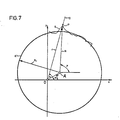
- 7 shows a diagram of an eccentrically arranged rotating body to be tested.
In Figur 1 ist eine Einrichtung zur Messung der Rundheitsabweichungen von Rotationskörpern schematisch dargestellt. In einem ortsfesten Rahmen 1 ist ein Rundtisch 2 mit einer Spindel 3 in einem Präzisionslager 4 drehbar gelagert. Die Spindel 3 wird mittels eines Riemens 5 von einem im Rahmen 1 befestigten Motor 6 angetrieben. Zur Ermittlung der Winkellage des Rundtisches 2 ist die Spindel 3 über eine Kupplung 7 mit einer Winkelmeßeinrichtung 8 starr verbunden. Auf der Oberfläche des Rundtisches 2 ist ein Rotationskörper 9 mit drei Rotationsflächen 9a, 9b, 9c angeordnet.In Figure 1, a device for measuring the roundness deviations of rotating bodies is shown schematically. A rotary table 2 with a
Die Rotationsflächen 9a. 9b, 9c des rotierenden Rotationskörpers 9 werden erfindungsgemäß vom Abtastkopf 10 einer digitalen Abtasteinrichtung 11 abgetastet, die von einem Arm 12 getragen wird. Auf dem Rahmen 1 ist eine senkrechte Säule 13 mit einem Vertikalschlitten 14 befestigt, der mittels einer Verstellschraube 15 höhenverstellbar ist. Im Vertikalschlitten 14 ist ein Horizontalschlitten 16 angeordnet, der mit dem Arm 12 verbunden und mittels einer Verstellschraube 17 horizontal verstellbar ist.The
In Figur 2 ist die Meßeinrichtung nach Figur 1 mit dem Rundtisch 2, der Spindel 3, der Winkelmeßeinrichtung 8, dem Rotationskörper 9 und der Abtasteinrichtung 11 vereinfacht dargestellt. Die digitalen Ausgangssignale der Abtasteinrichtung 11 werden über einen Vorwärts-/Rückwärtszähler 18 und die digitalen Ausgangssignale der Winkelmeßeinrichtung 8 über einen Vorwärts-/Rückwärtszähler 19 einem Digitalrechner 20 zugeleitet, der mit einer Anzeigeeinheit 21 und einer Druckeinrichtung 22 verbunden und von einer alphanumerischen Eingabeeinheit 23 beaufschlagt ist.In Figure 2, the measuring device according to Figure 1 with the rotary table 2, the
In Figur 3 ist ein kreisförmiger Rotationskörper K mit dem Radius R dargestellt, dessen Mittelpunkt A gegenüber einer Drehachse 0 um eine Exzentrizität e verschoben ist. Die Drehachse 0 möge sich im Ursprung eines Koordinatensystems y, x, befinden, so daß der Mittelpunkt A des Rotationskörpers K die Koordinaten xo, yo aufweist. Die Exzentrizität e schließt mit der x-Achse den Winkel α und der Momentanstrahl r mit der x-Achse den Winkel ψ ein.FIG. 3 shows a circular rotary body K with the radius R, the center A of which is shifted by an eccentricity e with respect to an axis of
Aus Figur 3 ergibt sich für den Momentanstrahl r in Abhängigkeit vom Winkel ϕ aus der Gleichung![]()
![]()
![]()
![]()
![]()
![]()
![]()
![]()
Durch den Term F2 = F20. cos 2 (ψ - a) mit der Periode π zeigt ein in Wirklichkeit kreisrunder Rotationskörper K bei exzentrischer Aufspannung einen scheinbaren elliptischen Fehler. Die Größe des maximalen elliptischen Fehlers F20 ist als Diagramm in den Figuren 4 und 5 in Abhängigkeit von der Exzentrizität e und dem Radius R des Rotationskörpers K dargestellt.By the term F 2 = F 20 . cos 2 (ψ - a) with the period π shows an actually circular rotation body K with an eccentric clamping an apparent elliptical error. The size of the maximum elliptical error F 20 is shown as a diagram in FIGS. 4 and 5 as a function of the eccentricity e and the radius R of the rotating body K.
In der Fourier-Entwicklung tritt als nächsthöheres Glied ein Term F3 mit dem maximalen Betrag Δ = e4/8R3 auf. Im allgemeinen resultieren durch dieses und die folgenden Glieder des Polynoms vernachlässigbar kleine Meßfehler. In Figur 6 ist die Exzentrizität e als Funktion des Radius R des Rotationskörpers K dargestellt. Diesem Diagramm ist zu entnehmen, daß beispielsweise für einen Roationskörper K mit einem Radius R = 50 mm und einer Exzentrizität e = 3 mm der maximale Betrag 0 kleiner als 0,1 µm ist. Die gestrichtelten Linien a und b in Figur 6 zeigen, daß die zulässige Exzentrizität e überschlägig mit R/10 bzw. R/20 angesetzt werden kann, wenn Δ kleiner als 1 µm bzw. kleiner als 0,1 µm bleiben soll. Da der Term F3 und die folgenden Glieder des Polynoms vernachlässigt werden können, ergibt sich für den Momentanstrahl r in Abhängigkeit von Winkel ϕ![]()
![]()
Damit ist gezeigt, daß mit den vorgeschlagenen Maßnahmen des visuellen groben Zentrierens des Rotationskörpers 9 bezüglich der Drehachse 0 innerhalb der oben angegebenen Grenzen für die Exzentrizität e, der Verwendung einer Abtasteinrichtung 11 mit großem Meßbereich zur Ermittlung der Rundheitsabweichungen des Rotationskörpers 9 und der Elimination der Exzentrizität e und des elliptischen Fehlers F2 unter Hinzuziehung des Digitalrechners 20 sehr genaue Rundheitsmessungen vorgenommen werden können. Darüberhinaus können gegebenenfalls die oben angegebenen Grenzen für die Exzentrizität e erweitert werden, wenn erfindungsgemäß die nachfolgenden Glieder der Fourier-Entwicklung eliminiert werden.This shows that with the proposed measures of visually coarse centering of the
Zur Messung der Rundheitsabweichungen des Rotationskörpers 9 wird von der digitalen Abtasteinrichtung 11 der Meßwert M in Abhängigkeit von Winkel ϕ![]()
- Mo willkürlich durch den Anfangswert bestimmt wird und
- F die Rundheitsabweichung des
Rotationskörpers 9 bedeutet.
- M o is determined arbitrarily by the initial value and
- F means the roundness deviation of the
rotating body 9.
Die einzelnen Meßwerte Mi werden regelmäßig über den Winkel 2π verteilt ermittelt. Hierfür werden von der Winkelmeßeinrichtung 8 n Meßpositionen über den Winkel 2π definiert. Die Zahl n muß so groß gewählt werden, daß das Profil der zu prüfenden Rotationsfläche 9a, 9b, 9c des Rotationskörpers 9 mit genügender Sicherheit ermittelt werden kann. Nach oben hin ist die Zahl n durch die Speicherkapazität des Digitalrechners 20 begrenzt. Die Zahl n der Meßpositionen wird zwischen 200 und 10000 liegen. 200 Meßwerte sind für die Ermittlung der Rundheitsabweichungen des Rotationskörpers (9) als Minimum anzusehen. Einige 1 000 Meßwerte sind heute in einem Digitalrechner mit vertretbarer Speichergröße in ausreichend kurzer Zeit zu verarbeiten.The individual measured values M i are regularly distributed over the angle 2π. For this purpose, 8 n measuring positions are defined by the angle measuring device over the angle 2π. The number n must be chosen so large that the profile of the
Im Digitalrechner 20 wird zur Ermittlung der Werte Mo, xo und yo (xo und yo sind die Koordinaten des Mittelpunktes A des Rotationskörpers 9 bezüglich der Drehachse 0) folgende Auswertung vorgenommen :![]()
![]()
![]()
![]()
![]()
![]()
Daraus läßt sich die Exzentrizität e![]()
![]()
![]()
![]()
Damit läßt sich die Rundheitsabweichung F des Rotationskörpers 9![]()
![]()
Zur Ermittlung des absoluten Radius R des Rotationskörpers 9 wird die Rundheitsmeßeinrichtung mit Hilfe eines Eichzylinders mit bekannten Radius RE und unter Durchführung einer Rundheitsmessung und Bestimmung der Werte Mo = Moe und e2/4RE geeicht. Daraus errechnet sich ein Korrekturwert E![]()
![]()
![]()
![]()
Der Digitalrechner 20 dient zur Speicherung der Meßwerte, zur Elimination der Exzentrizität e und des scheinbaren elliptischen Fehlers F2 sowie gegebenenfalls der Fehler höherer Ordnung zur Berechnung der Rundheitsabweichungen und zur Fourier-Analyse der Rundheitsabweichungen sowie gegebenenfalls zur statistischen Auswertung einer Reihe von Rundheitsmessungen ; des weiteren kann die Konzentrizität mehrerer Rotationsflächen 9a, 9b, 9c des Rotationskörpers 9 bzw. die Schräglage der Rotationsachse des Rotationskörpers 9 bezüglich der Auflagefläche ermittelt werden.The
Das Meßergebnis kann auf der Druckeinrichtung 22 in Form eines X-Y-Schreibers oder eines Polarschreibers oder auf einer Anzeigeeinrichtung 21 mit einem Bildschirm in Form eines polaren Rundheitsfehlerdiagramms dargestellt werden.The measurement result can be displayed on the
In einer weiteren Ausbildung der Erfindung wird vorgeschlagen, die Parameter Ro, e, a eines an die Profilform des Rotationskörpers 9 bestangepaßten Kreises K' mit den bekannten Verfahren der Ausgleichsrechnung zu ermitteln, wobei Ro der Radius des Kreises K', e die Exzentrizität und a der Winkel zwischen der Richtung der Exzentrizität e und der Richtung x eines vorgegebenen Koordinatensystems x, y bedeuten (Figur 7). Die auf diesen Kreis K' bezogene Rundheitsabweichung F = R - R0 des Rotationskörpers 9 kann dann exakt nach der Gleichung![]()
![]()
Claims (5)
Priority Applications (1)
| Application Number | Priority Date | Filing Date | Title |
|---|---|---|---|
| AT82102711T ATE16636T1 (en) | 1981-06-13 | 1982-03-31 | METHOD OF MEASUREMENT OF THE ROUNDNESS DEVIATIONS OF ROTATIONAL BODIES. |
Applications Claiming Priority (2)
| Application Number | Priority Date | Filing Date | Title |
|---|---|---|---|
| DE3123489 | 1981-06-13 | ||
| DE19813123489 DE3123489A1 (en) | 1981-06-13 | 1981-06-13 | METHOD FOR MEASURING THE ROUNDNESS DIFFERENCES OF ROTATION BODIES AND DEVICES FOR IMPLEMENTING THE METHOD |
Publications (3)
| Publication Number | Publication Date |
|---|---|
| EP0068082A2 EP0068082A2 (en) | 1983-01-05 |
| EP0068082A3 EP0068082A3 (en) | 1983-02-09 |
| EP0068082B1 true EP0068082B1 (en) | 1985-11-21 |
Family
ID=6134632
Family Applications (1)
| Application Number | Title | Priority Date | Filing Date |
|---|---|---|---|
| EP82102711A Expired EP0068082B1 (en) | 1981-06-13 | 1982-03-31 | Process for measuring the out-of-roundness of rotation-symmetrical articles |
Country Status (4)
| Country | Link |
|---|---|
| EP (1) | EP0068082B1 (en) |
| JP (1) | JPS57207813A (en) |
| AT (1) | ATE16636T1 (en) |
| DE (1) | DE3123489A1 (en) |
Families Citing this family (26)
| Publication number | Priority date | Publication date | Assignee | Title |
|---|---|---|---|---|
| GB2148007B (en) * | 1983-10-01 | 1988-02-10 | Rolls Royce Motor Cars | Profile checking apparatus |
| US4642902A (en) * | 1984-06-26 | 1987-02-17 | Siemens Aktiengesellschaft | Apparatus for determining the deviations from a circular form in a dynamically balanced part |
| WO1986002996A1 (en) * | 1984-11-15 | 1986-05-22 | Elgema Gmbh | Device for measuring the profile form of cylindrical workpiece surfaces |
| GB8605324D0 (en) * | 1986-03-04 | 1986-04-09 | Rank Taylor Hobson Ltd | Metrological apparatus |
| US4800652A (en) * | 1987-09-25 | 1989-01-31 | The Timken Company | Machine for measuring generally circular objects in cylindrical coordinates |
| DE3807551A1 (en) * | 1988-03-08 | 1989-09-21 | Teves Gmbh Alfred | Holding (locating, fixing) device for a brake drum |
| DE8817019U1 (en) * | 1988-09-23 | 1991-11-28 | Mauser-Werke Oberndorf Gmbh, 7238 Oberndorf, De | |
| JPH02105007A (en) * | 1988-10-14 | 1990-04-17 | Topy Ind Ltd | Method and device for measuring shape of wheel rim or the like |
| US5151870A (en) * | 1989-11-17 | 1992-09-29 | Illinois Tool Works Inc. | Apparatus and method for determining a center and measuring with reference thereto |
| AT399396B (en) * | 1990-03-29 | 1995-04-25 | Oesterr Forsch Seibersdorf | METHOD FOR DETERMINING THE AXIS OF A LONG-STRETCHED OBJECT |
| GB2294327A (en) * | 1994-10-18 | 1996-04-24 | Rank Taylor Hobson Ltd | Roundness measuring |
| GB2317453B (en) * | 1996-09-20 | 2000-12-06 | Rank Taylor Hobson Ltd | Bearing measurement system |
| DE19851954A1 (en) * | 1998-11-11 | 2000-05-18 | Mahle Gmbh | Measuring method and system for rotating parts, in particular for pistons of piston machines |
| JP3738844B2 (en) * | 2002-09-04 | 2006-01-25 | 株式会社東京精密 | Roundness measuring machine |
| JP4663385B2 (en) * | 2005-04-18 | 2011-04-06 | 株式会社ブリヂストン | Method for correcting irregularities on the surface of a rotating body |
| DE102006015627B4 (en) * | 2006-03-31 | 2008-03-27 | Innovent E.V. | Method and device for determining and measuring shape deviations and undulations on rotationally symmetrical parts |
| JP2008286535A (en) | 2007-05-15 | 2008-11-27 | Mitsutoyo Corp | Apparatus, method and program for measuring roundness |
| DE102009032353A1 (en) | 2009-07-08 | 2011-09-08 | Hommel-Etamic Gmbh | Method for determining the shape of a workpiece |
| US9133750B2 (en) | 2009-07-30 | 2015-09-15 | GM Global Technology Operations LLC | Method and system for verifying the operation of an SCR catalyst |
| DE102009042252B4 (en) | 2009-09-22 | 2014-03-06 | Jenoptik Industrial Metrology Germany Gmbh | measuring device |
| GB2478303B (en) * | 2010-03-02 | 2018-03-07 | Taylor Hobson Ltd | Surface measurement instrument and calibration thereof |
| DE102010013069B4 (en) | 2010-03-26 | 2012-12-06 | Hommel-Etamic Gmbh | measuring device |
| DE102010035147B4 (en) | 2010-08-23 | 2016-07-28 | Jenoptik Industrial Metrology Germany Gmbh | measuring device |
| CN102147331B (en) * | 2010-11-25 | 2012-09-05 | 哈尔滨工业大学 | Mounting eccentric error compensating method based on CNC (Computerized Numerical Control) gear measuring center |
| DE102012018580B4 (en) | 2012-09-20 | 2015-06-11 | Jenoptik Industrial Metrology Germany Gmbh | Measuring device and measuring method for in-process measurement on test specimens during a machining operation on a processing machine, in particular a grinding machine |
| CN110530306B (en) * | 2019-08-27 | 2020-10-20 | 大连理工大学 | Typical revolving body part characterization method based on actually measured run-out data |
Family Cites Families (5)
| Publication number | Priority date | Publication date | Assignee | Title |
|---|---|---|---|---|
| DE1100978B (en) * | 1958-07-11 | 1961-03-02 | Johannes Perthen Dr Ing | Method and device for checking the surface and faulty shape of a workpiece |
| GB981865A (en) * | 1960-02-17 | 1965-01-27 | Rank Precision Ind Ltd | Measuring and recording arrangements |
| GB933785A (en) * | 1960-11-16 | 1963-08-14 | Rank Precision Ind Ltd | Improvements in or relating to testing the profiles of surface sections |
| DE1302862B (en) * | 1962-08-28 | 1971-01-07 | ||
| JPS5698602A (en) * | 1980-01-11 | 1981-08-08 | Mitsubishi Electric Corp | Shape measurement method for cylinder or column |
-
1981
- 1981-06-13 DE DE19813123489 patent/DE3123489A1/en not_active Ceased
-
1982
- 1982-03-31 AT AT82102711T patent/ATE16636T1/en not_active IP Right Cessation
- 1982-03-31 EP EP82102711A patent/EP0068082B1/en not_active Expired
- 1982-05-27 JP JP57088975A patent/JPS57207813A/en active Pending
Non-Patent Citations (1)
| Title |
|---|
| Feinwerktechnik und Messtechnik 87 (1979) 5, Seiten 227-232 * |
Also Published As
| Publication number | Publication date |
|---|---|
| EP0068082A3 (en) | 1983-02-09 |
| DE3123489A1 (en) | 1982-12-30 |
| EP0068082A2 (en) | 1983-01-05 |
| JPS57207813A (en) | 1982-12-20 |
| ATE16636T1 (en) | 1985-12-15 |
Similar Documents
| Publication | Publication Date | Title |
|---|---|---|
| EP0068082B1 (en) | Process for measuring the out-of-roundness of rotation-symmetrical articles | |
| DE60315050T2 (en) | DEVICE AND METHOD FOR MEASURING, COMPENSATING AND TESTING A NUMERICALLY CONTROLLED TOOL HEAD AND / OR TABLE | |
| EP3049758B1 (en) | Reduction of errors of a rotating device used during the determination of co-ordinates of a workpiece or during the machining of a workpiece | |
| EP1923670B1 (en) | Position measuring device | |
| EP2729768B1 (en) | Calibration and operation of rotating devices, in particular for rotating sensing heads and/or probes of coordinate measuring devices | |
| DE60018412T2 (en) | CONTROL UNIT FOR MEASURING INSTRUMENT | |
| DE69532380T2 (en) | ROUNDNESS FAIRS | |
| DE60311527T2 (en) | WORKPIECE INSPECTION PROCESS AND DEVICE | |
| EP2108105B1 (en) | Method for determining an influencing variable on the eccentricity of an angle measuring device | |
| EP0732563A1 (en) | Coordinate measuring machine incorporating a device for roughness measurement | |
| DE10115288B4 (en) | Measuring device for surface structures and measuring methods for surface structures | |
| EP0019075A1 (en) | Process and apparatus for examining the tooth flank profiles of large-diameter gear wheels | |
| DE1302862B (en) | ||
| WO1986002996A1 (en) | Device for measuring the profile form of cylindrical workpiece surfaces | |
| DE3801413C2 (en) | ||
| EP0106181B1 (en) | Control process to determine the exactitude of tooling machines, and device to carry out the process | |
| DE2938662C2 (en) | ||
| DE10056956B4 (en) | Method and device for assessing an eccentric position of an acceleration sensor | |
| DE4134690C2 (en) | Method and device for measuring the shape, size and spatial position of coaxial rotation surfaces and perpendicular end faces on cylindrical workpieces | |
| EP0514726B1 (en) | Method for making allowance for deviation of the crank pin position of a crankshaft during balancing and device therefor | |
| DE102017119488B9 (en) | A method for determining the cumulative pitch deviations of positional incarnations of a workpiece with a circular graduation | |
| DE2354248A1 (en) | Rotating element testing method - tests for irregularity of dimensions when element is slowly rotated about its axis | |
| DE102015201582B4 (en) | Determination and correction of an error in a rotary device for a coordinate measuring machine | |
| DE19818405B4 (en) | Method for detecting geometric deviations of at least one axis of a coordinate measuring machine | |
| DE2615073C2 (en) |
Legal Events
| Date | Code | Title | Description |
|---|---|---|---|
| PUAI | Public reference made under article 153(3) epc to a published international application that has entered the european phase |
Free format text: ORIGINAL CODE: 0009012 |
|
| PUAL | Search report despatched |
Free format text: ORIGINAL CODE: 0009013 |
|
| 17P | Request for examination filed |
Effective date: 19820407 |
|
| AK | Designated contracting states |
Designated state(s): AT CH FR GB IT LI NL SE |
|
| AK | Designated contracting states |
Designated state(s): AT CH FR GB IT LI NL SE |
|
| ITF | It: translation for a ep patent filed |
Owner name: VETTOR GALLETTI DI SAN CATALDO |
|
| GRAA | (expected) grant |
Free format text: ORIGINAL CODE: 0009210 |
|
| AK | Designated contracting states |
Designated state(s): AT CH FR GB IT LI NL SE |
|
| PG25 | Lapsed in a contracting state [announced via postgrant information from national office to epo] |
Ref country code: LI Free format text: LAPSE BECAUSE OF NON-PAYMENT OF DUE FEES Effective date: 19851121 Ref country code: CH Free format text: LAPSE BECAUSE OF NON-PAYMENT OF DUE FEES Effective date: 19851121 |
|
| REF | Corresponds to: |
Ref document number: 16636 Country of ref document: AT Date of ref document: 19851215 Kind code of ref document: T |
|
| ET | Fr: translation filed | ||
| PLBI | Opposition filed |
Free format text: ORIGINAL CODE: 0009260 |
|
| 26 | Opposition filed |
Opponent name: ELGEMA GMBH Effective date: 19860819 |
|
| NLR1 | Nl: opposition has been filed with the epo |
Opponent name: ELGEMA GMBH |
|
| PGFP | Annual fee paid to national office [announced via postgrant information from national office to epo] |
Ref country code: AT Payment date: 19870226 Year of fee payment: 6 |
|
| PGFP | Annual fee paid to national office [announced via postgrant information from national office to epo] |
Ref country code: NL Payment date: 19870331 Year of fee payment: 6 |
|
| PG25 | Lapsed in a contracting state [announced via postgrant information from national office to epo] |
Ref country code: GB Effective date: 19890331 Ref country code: AT Effective date: 19890331 |
|
| PG25 | Lapsed in a contracting state [announced via postgrant information from national office to epo] |
Ref country code: SE Effective date: 19890401 |
|
| PG25 | Lapsed in a contracting state [announced via postgrant information from national office to epo] |
Ref country code: NL Effective date: 19891001 |
|
| NLV4 | Nl: lapsed or anulled due to non-payment of the annual fee | ||
| PG25 | Lapsed in a contracting state [announced via postgrant information from national office to epo] |
Ref country code: FR Free format text: LAPSE BECAUSE OF NON-PAYMENT OF DUE FEES Effective date: 19891130 |
|
| REG | Reference to a national code |
Ref country code: CH Ref legal event code: PL |
|
| GBPC | Gb: european patent ceased through non-payment of renewal fee | ||
| REG | Reference to a national code |
Ref country code: FR Ref legal event code: ST |
|
| RAP4 | Party data changed (patent owner data changed or rights of a patent transferred) |
Owner name: DR. JOHANNES HEIDENHAIN GMBH |
|
| RDAG | Patent revoked |
Free format text: ORIGINAL CODE: 0009271 |
|
| STAA | Information on the status of an ep patent application or granted ep patent |
Free format text: STATUS: PATENT REVOKED |
|
| 27W | Patent revoked |
Effective date: 19901107 |
|
| GBPR | Gb: patent revoked under art. 102 of the ep convention designating the uk as contracting state | ||
| EUG | Se: european patent has lapsed |
Ref document number: 82102711.7 Effective date: 19891114 |