EP0068067A1 - High voltage resistor for open air insulating arrangements - Google Patents
High voltage resistor for open air insulating arrangements Download PDFInfo
- Publication number
- EP0068067A1 EP0068067A1 EP82100844A EP82100844A EP0068067A1 EP 0068067 A1 EP0068067 A1 EP 0068067A1 EP 82100844 A EP82100844 A EP 82100844A EP 82100844 A EP82100844 A EP 82100844A EP 0068067 A1 EP0068067 A1 EP 0068067A1
- Authority
- EP
- European Patent Office
- Prior art keywords
- voltage
- insulator
- voltage resistor
- resistor
- resistor according
- Prior art date
- Legal status (The legal status is an assumption and is not a legal conclusion. Google has not performed a legal analysis and makes no representation as to the accuracy of the status listed.)
- Granted
Links
Images


Classifications
-
- H—ELECTRICITY
- H01—ELECTRIC ELEMENTS
- H01B—CABLES; CONDUCTORS; INSULATORS; SELECTION OF MATERIALS FOR THEIR CONDUCTIVE, INSULATING OR DIELECTRIC PROPERTIES
- H01B17/00—Insulators or insulating bodies characterised by their form
- H01B17/42—Means for obtaining improved distribution of voltage; Protection against arc discharges
Definitions
- the invention relates to a high-voltage resistor to avoid flashovers for outdoor insulation assemblies, consisting of an insulating body and a resistance material, which is connected in series with an insulator.
- a high-voltage resistor to avoid flashovers for outdoor insulation assemblies, consisting of an insulating body and a resistance material, which is connected in series with an insulator.
- one or more high-voltage resistors or high-voltage insulators of any design, such as Long rods, support and cap insulators can be used for both DC and AC voltages.
- the high-voltage resistor is intended to prevent flashovers caused by conductive foreign layers, in particular moistened dirt deposits on the surface of outdoor insulators. With such conductive surfaces, a so-called foreign layer leakage current flows first. With this current, foreign layers are dried out at the points of greatest current density and so-called drying zones are formed. These drying zones are then bridged by partial arcs due to the uneven voltage distribution that arises. If the conductivity of the still wet zones is too high, the partial arcs are extended and there is a flashover in the conductor earth voltage.
- One tries to prevent this flashover by either increasing the creepage distances while maintaining the insulator shape by increasing the overall length or by using insulators with a longer creepage distance while maintaining the overall length.
- a cylindrical resistor in series is assigned to the insulator to avoid flashover. This resistance is dimensioned such that the flowing leakage current over the surface of the insulator remains small and does not exceed a certain value.
- the resistors required for this must have a resistance value in the range of a few megohms to a hundred megohms.
- the disadvantage of this system is that after the formation of a conductive layer on the insulator, almost the entire conductor earth voltage has to be taken over by the resistor, since the value of the surface resistance of the insulator becomes very much lower than that of the resistor connected in series when it is very dirty. Such an insulation arrangement thus becomes very long.
- the arrangement becomes ineffective if a conductive layer forms on the surface of the series resistor due to contamination, so that one is forced, e.g. to install conical covers against pollution, as is apparent from the embodiment of the British patent.
- the object of the present invention is to be seen in specifying a high-voltage resistor for use in a series connection with a high-voltage insulator for outdoor insulation arrangements, in which no flashover occurs on the overall arrangement despite conductive foreign layers and a low overall height can be achieved.
- the object is achieved in that the leakage current pulse characteristic of the high-voltage insulator on the total resistance the high-voltage resistor caused a voltage drop of at least 5, preferably 10-30% of the total conductor earth voltage and its shape is modeled on a shield insulator.
- this high-voltage resistor must be resistant to arcing and breakdown and must be designed so that an electrically parallel conductive layer on its surface changes its total resistance value only slightly.
- this is achieved by means of outer contours with a comparatively high specific creepage distance and, if one wishes to obtain an even shorter overall length of the outdoor insulation arrangement, by forming the outer surface from a hydrophobic material such as polytetrafluoroethylene (PTFE), ethylene propylene monomer (EPM), ethylene propylene diene monomer (EPDM). or silicone rubber reached.
- a hydrophobic material such as polytetrafluoroethylene (PTFE), ethylene propylene monomer (EPM), ethylene propylene diene monomer (EPDM). or silicone rubber reached.
- PTFE polytetrafluoroethylene
- EPM ethylene propylene monomer
- EPDM ethylene propylene diene monomer
- silicone rubber silicone rubber
- the insulating body can consist of ceramic, glass or plastic and the resistance material can be applied to it in the form of spirals or conductive or semiconductive layers.
- a special embodiment of the inventive idea is that the insulating body is hollow.
- Other features regarding the embodiment of the invention go from the subclaims or from the description.
- An advantage of the embodiment of the device according to the invention consists in a small overall length of the entire insulation arrangement, as a result of which an economical and, as a result of the lower mast height of an overhead line, an environmentally friendly design is achieved.
- it proves to be particularly advantageous in the context of the invention that existing insulation arrangements in which the foreign-layer loads have become stronger over time can be prevented from flashover or from constant cleaning by using the high-voltage resistor according to the invention in series built in.
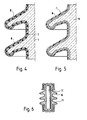
- the device according to the invention of the high-voltage resistor 1, 1a, 1b is shown in series with the actual outdoor insulator 2, 2a, 2b in FIGS. 1 to 3, the outdoor insulator in FIG. 1 as a long bar insulator, in FIG. 2 as a post insulator and in FIG. 3 is shown as a chain of cap insulators.
- a resistor for use with a long bar insulator 2 is shown in section. It consists of a resistance wire 3 which is applied to the surface of an insulating body 4 e.g. a porcelain insulator is applied in a spiral shape and is embedded in a glaze 5. The surface is covered with a hydrophobic layer 6 e.g. made of silicone rubber.
- FIG. 5 Another embodiment is shown in FIG. 5.
- a conductive glaze 7 is applied to the surface of the insulating body 4, on which in turn a hydrophobic layer 6 is applied.
- Wire or film resistors designed in this way can of course not only be used for long-rod insulators, but also for post insulators, a chain of cap insulators or for bushings, since there are no technical difficulties in adapting the shield shape of the resistor to the shape of these insulators.
- an insulating body 4 being used which is cylindrical.
- One or more parallel resistance wires 3 are embedded in the glaze on the cylindrical surface, similar to the conventional glazed wire resistors: Shields 8 made of open-air resistant plastic material such as e.g. Silicone rubber applied in the form of insulator shields.
- FIG. 10 differs from FIG. 9 only in that instead of a wire resistor, a sheet resistor 9 is used, which is either formed by a conductive glaze or by a thin metal layer, the resistor being either continuous or spiral.
- a wire resistor instead of a wire resistor, a sheet resistor 9 is used, which is either formed by a conductive glaze or by a thin metal layer, the resistor being either continuous or spiral.
- FIG. 6 A further embodiment of the resistor can also be seen in FIG. 6.
- a cylindrical resistor 10 inside a hollow insulator 11.
- the surface of the hollow insulator can in turn be coated with a hydrophobic material 6.
- High-voltage resistors in the embodiment according to FIG. 6 can be used for outdoor insulation arrangements with long rods Fig. 1 or supports according to Fig. 2 are used, wherein the insulating body 11 must be mechanically sufficiently strong. 6 can also be used advantageously in outdoor insulation arrangements without meeting high mechanical requirements.
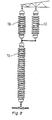
- Such an arrangement of the high-voltage resistor 15 for a long-rod insulator 19 is shown in FIG. 8. The insulator 18 only serves to take over the mechanical forces of the actual insulator 19; it is bridged electrically by the resistor 15 connected in parallel.
- the effectiveness of the cylindrical resistor 10 according to FIG. 6 must not be significantly impaired by the additional electrical parallel connection of the surface of the uppermost long rod insulator 18, which is conductive due to contamination, to the outer surface of the resistor 15, which is conductive due to contamination.
- This requirement can usually be met with a suitable design of the shields and the surfaces of the long rod insulator 18 of the resistor 15 and the inventive dimensioning of the cylindrical resistor 10;
- a resistance value of the cylindrical resistor 10 of 20 kOhm can apply and a resistance value for the surface of the uppermost long rod 18, as well as the resistor 15, which is conductive due to heavy contamination about 100 kOhm.
- the insulating body 11 is also designed as a hollow insulator.
- the resistor 12 is formed in one of the embodiments of FIG. 4 or 5.
- Another embodiment is to integrate the high voltage resistor, as shown in FIG. 11, into the isolator of the outdoor isolation arrangement.
- the resistance can be implemented in the embodiment according to FIG. 4, as shown in FIG. 11, or according to FIG. 5.
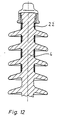
- the resistor is again integrated into the insulator of the outdoor arrangement, but, in contrast to FIG. 11, is arranged distributed.
- the distributed partial resistors 22 can again be constructed as shown in FIG. 4 or 5, as shown in FIG. 11.
- the resistor is constructed on the principle of a plastic composite insulator, with a fiber reinforced core 13 with conductive fibers, e.g. Carbon fiber is used, over which a shield cover 14, e.g. made of silicone rubber.
- a ceramic long rod L 75/22 with a length of 1270 mm and a creepage distance of 2440 mm was used as the insulator, in accordance with the regulations of DIN 48006/2.
- a standing salt content of 28 kg / m 3 at 63 kV was achieved with the resistor according to the invention for the conventional arrangement, that is to say without series connection.
- the critical leakage current pulse at the flashover was measured at 1072 mA (peak value). This leakage current pulse is characteristic of the isolator used. The tests were carried out with a rigid voltage source (short-circuit current 20 A).
- an inventive resistor according to FIG. 6 with an overall length of 160 mm was additionally used, which had a resistance value of 13 kOhm and was connected in series with the insulator L75 / 22.
- the insulator could not even with the highest possible salinity (224 kg / m 3 ) more to roll over.
- the highest leakage current pulse was 2110 mA.
- the comparatively tested arrangement consisted of the isolator chain, to which an inventive high-voltage resistor of 13 kOhm was connected in series. Salinity, 224 kg / m l in the same test voltage of 60.6 kV, the cap chain could not be brought to flashover. In the test without flashover, the highest leakage current pulse was 5515 mA.
Abstract
Die Erfindung bezieht sich auf einen Freiluft-Hochspannungsisolator, bei dem ein Überschlag unter Fremdschichteneinfluß (Schmutzablagerung) verhindert oder zumindest in Richtung auf höheren Verschmutzungsgrad verschoben wird. Erfindungsgemäß wird mit dem eigentlichen Isolator (2) ein Widerstandselement (1) in Reihe geschaltet, an dem der einem Überschlag vorausgehende Fremdschicht-Ableitestrom einen Spannungsabfall erzeugt. Dieser Spannungsabfall reduziert die am Isolator anliegende Spannung und verhindert oder verzögert einen Überschlag.The invention relates to an outdoor high-voltage insulator, in which a flashover under the influence of foreign layers (dirt deposition) is prevented or at least shifted towards a higher degree of contamination. According to the invention, a resistance element (1) is connected in series with the actual insulator (2), on which the foreign layer leakage current preceding a flashover generates a voltage drop. This voltage drop reduces the voltage across the insulator and prevents or delays a flashover.
Description
Die Erfindung betrifft einen Hochspannungswiderstand zur Vermeidung von Fremdschicht-Uberschlägen für Freiluft-Isolieranordnungen, bestehend aus einem Isolierkörper und einem Widerstandsmaterial, der in Reihe mit einem Isolator geschaltet ist. Für solche Anordnungen können ein oder mehrere Hochspannungswiderstände bzw. Hochspannungs-Isolatoren beliebiger Bauform wie z.B. Langstäbe, Stütz- und Kappenisolatoren sowohl für Gleich- als auch Wechselspannungen verwendet werden.The invention relates to a high-voltage resistor to avoid flashovers for outdoor insulation assemblies, consisting of an insulating body and a resistance material, which is connected in series with an insulator. For such arrangements, one or more high-voltage resistors or high-voltage insulators of any design, such as Long rods, support and cap insulators can be used for both DC and AC voltages.
Mit dem Hochspannungswiderstand will man Überschläge vermeiden, die durch leitfähige Fremdschichten, insbesondere befeuchtete Schmutzablagerungen auf der Oberfläche von Freiluft-Isolatoren entstehen. Bei solchen leitfähigen Oberflächen fließt zuerst ein sogenannter Fremdschicht-Ableitstrom. Durch diesen Strom werden an den Stellen größter Stromdichte Fremdschichten ausgetrocknet und sog. Trockenzonen gebildet. Diese Trockenzonen werden dann wegen der sich einstellenden ungleichmäßigen Spannungsverteilung durch Teillichtbögen überbrückt. Ist die Leitfähigkeit der noch feuchten Zonen zu groß, dann verlängern sich die Teillichtbögen und es kommt schließlich zu einem Überschlag bei der Leiter-Erdspannung. Diesen Überschlag versucht man zu verhindern, indem man entweder unter Beibehaltung der Isolatorform durch Vergrößerung der Baulänge die Kriechwege erhöht oder unter Beibehaltung der Baulänge Isolatoren mit größerer Kriechweglänge einsetzt. Diese beiden Maßnahmen sind aber nur im beschränkten Umfang möglich, so daß bei stärkerer Verschmutzung noch Überschläge auftreten können. Bei sehr starker Verschmutzung führen diese Maßnahmen allein zu keinem Erfolg. Deshalb hat man versucht, wie aus der GB-PS 1 039 193 hervorgeht, Hochspannungsisolatoren mit einer leitfähigen Oberfläche zu versehen, um so eine ungleichmäßige Spannungsverteilung zu vermeiden, die für die Ausbildung von Teillichtbögen verantwortlich ist. Insbesondere soll die dort vorgeschlagene halbleitende Glasur erreichen, daß die erforderliche Befeuchtung durch die Erwärmung des Isolators verhindert wird. Der Nachteil dieser Lösung besteht darin, daß ständig hohe Ableitstromverluste entstehen. Außerdem sind solche Oberflächenschichten für große Isolatoren mit der erforderlichen Gleichmäßigkeit, thermischen Stabilität und Alterungsbeständigkeit nur schwer herstellbar.The high-voltage resistor is intended to prevent flashovers caused by conductive foreign layers, in particular moistened dirt deposits on the surface of outdoor insulators. With such conductive surfaces, a so-called foreign layer leakage current flows first. With this current, foreign layers are dried out at the points of greatest current density and so-called drying zones are formed. These drying zones are then bridged by partial arcs due to the uneven voltage distribution that arises. If the conductivity of the still wet zones is too high, the partial arcs are extended and there is a flashover in the conductor earth voltage. One tries to prevent this flashover by either increasing the creepage distances while maintaining the insulator shape by increasing the overall length or by using insulators with a longer creepage distance while maintaining the overall length. However, these two measures are only possible to a limited extent, so that flashovers can still occur in the event of heavy pollution. In the case of very heavy pollution, these measures alone do not lead to success. Therefore, as is apparent from GB-
Eine andere Maßnahme geht aus der GB-PS 1 296 038 hervor. Zur Vermeidung von Fremdschicht-Überschlägen wird dem Isolator ein zylinderförmiger Widerstand in Reihe zugeordnet. Dieser Widerstand ist so bemessen, daß der fließende Ableitstrom über die Oberfläche des Isolators klein bleibt und einen bestimmten Wert nicht überschreitet. Die hierfür erforderlichen Widerstände müssen einen Widerstandswert im Bereich einiger Mega-Ohm bis hundert Mega-Ohm aufweisen. Nachteilig ist bei diesem System, daß nach Bildung einer leitfähigen Schicht am Isolator nahezu die gesamte Leiter-Erdspannung vom Widerstand übernommen werden muß, da der Wert des Oberflächenwiderstands des Isolators bei starker Verschmutzung sehr viel niedriger als der des in Reihe geschalteten Widerstands wird. Damit wird eine solche Isolieranordnung sehr lang. Außerdem wird die Anordnung unwirksam, wenn sich auf der Oberfläche des in Reihe geschalteten Widerstandes durch Verschmutzung eine leitfähige Schicht ausbildet, so daß man gezwungen ist, z.B. kegelförmige Abdeckungen gegen die Verschmutzung anzubringen, wie dies aus dem Ausführungsbeispiel des britischen Patents hervorgeht.Another measure emerges from GB-
Die Aufgabe der vorliegenden Erfindung ist darin zu sehen, einen Hochspannungswiderstand zur Verwendung in einer Reihenschaltung mit einem Hochspannungsisolator für Freiluft-Isolieranordnungen anzugeben, bei dem trotz leitender Fremdschichten kein Überschlag an der Gesamtanordnung mehr auftritt und eine geringe Bauhöhe erreichbar ist.The object of the present invention is to be seen in specifying a high-voltage resistor for use in a series connection with a high-voltage insulator for outdoor insulation arrangements, in which no flashover occurs on the overall arrangement despite conductive foreign layers and a low overall height can be achieved.
Die Aufgabe wird dadurch gelöst, daß der für den HochspannungsIsolator charakteristische Ableitstromimpuls am Gesamtwiderstand des Hochspannungswiderstands einen Spannungsabfall von mindestens 5, vorzugsweise 10 - 30% der gesamten Leiter-Erdspannung hervorruft und seine Form einem Schirmisolator nachgebildet ist. Dieser Hochspannungswiderstand muß für diese Spannung überschlags- und durchschlagsfest sein und so ausgebildet werden, daß eine auf seiner Oberfläche vorhandene elektrisch parallel geschaltete leitfähige Fremdschicht seinen Gesamtwiderstandwert nur geringfügig verändert. Dies wird erfindungsgemäß durch Außenkonturen mit vergleichsweise hohem spezifischen Kriechweg und, wenn man eine noch kürzere Baulänge der Freiluft-Isolieranordnung erhalten will, durch Ausbildung der äußeren Oberfläche aus einem hydrophoben Material wie z.B. Polytetrafluoräthylen (PTFE), Äthylenpropylenmonomer (EPM), Äthylenpropylendienmonomer (EPDM) oder Silikongummi erreicht. Durch die Hydrophobie der genannten Kunststoffe ist gewährleistet, daß der Wert des Oberflächenwiderstandes auch bei Fremdschicht-Beanspruchung wesentlich größer als der Wert des Widerstandes ist. Außerdem ähnelt der Hochspannungswiderstand in äußerer Form und Aufbau einem Schirmisolator. Die Reihenfolge der Anordnung eines solchen Hochspannungswiderstandes in der Freiluft-Isolieranordnung spielt keine Rolle; er kann somit erd- als auch spannungsnah geschaltet, zwischen zwei Isolatoren oder auch aufgeteilt an mehreren Stellen angeordnet werden. Die Wirkung dieser Anordnung beruht in der überraschenden Feststellung, daß durch die auftretende Spannungsabsenkung ein Überschlag auch bei Überschreitung des charakteristischen kritischen Ableitstromimpulses vermieden wird.The object is achieved in that the leakage current pulse characteristic of the high-voltage insulator on the total resistance the high-voltage resistor caused a voltage drop of at least 5, preferably 10-30% of the total conductor earth voltage and its shape is modeled on a shield insulator. For this voltage, this high-voltage resistor must be resistant to arcing and breakdown and must be designed so that an electrically parallel conductive layer on its surface changes its total resistance value only slightly. According to the invention, this is achieved by means of outer contours with a comparatively high specific creepage distance and, if one wishes to obtain an even shorter overall length of the outdoor insulation arrangement, by forming the outer surface from a hydrophobic material such as polytetrafluoroethylene (PTFE), ethylene propylene monomer (EPM), ethylene propylene diene monomer (EPDM). or silicone rubber reached. The hydrophobicity of the plastics mentioned ensures that the value of the surface resistance is significantly greater than the value of the resistance even when exposed to foreign layers. In addition, the high-voltage resistor is similar in shape and structure to a shield insulator. The order in which such a high-voltage resistor is arranged in the outdoor insulation arrangement is irrelevant; it can thus be connected close to ground as well as voltage, between two insulators or also divided at several locations. The effect of this arrangement is based on the surprising finding that a flashover is avoided by the voltage drop occurring even if the characteristic critical leakage current pulse is exceeded.
Im einzelnen kann der Isolierkörper aus Keramik, Glas oder Kunststoff bestehen und das Widerstandsmaterial in Form von den Spiralen oder leitenden bzw. halbleitentSchichten darauf aufgetragen sein.In particular, the insulating body can consist of ceramic, glass or plastic and the resistance material can be applied to it in the form of spirals or conductive or semiconductive layers.
Eine besondere Ausbildung des erfinderischen Gedankens besteht darin, daß der Isolierkörper hohl ausgebildet ist. Weitere Merkmale hinsichtlich der Ausführungsform der Erfindung gehen aus den Unteransprüchen bzw. aus der Beschreibung hervor.A special embodiment of the inventive idea is that the insulating body is hollow. Other features regarding the embodiment of the invention go from the subclaims or from the description.
Ein Vorteil der erfindungsgemäßen Ausführungsform der Vorrichtung besteht in einer geringen Baulänge der gesamten Isolieranordnung, wodurch eine wirtschaftliche und in Folge der geringeren Masthöhe einer Freileitung auch eine umweltschonendere Ausführung erreicht wird. Außerdem erweist es sich im Rahmen der Erfindung als besonders vorteilhaft, daß bestehende Isolieranordnungen, bei denen im Laufe der Zeit die Fremdschicht-Belastungen stärker geworden sind, vor dem Überschlag, bzw. vor ständiger Reinigung bewahrt werden können, indem man den erfindungsgemäßen Hochspannungswiderstand in Reihe einbaut.An advantage of the embodiment of the device according to the invention consists in a small overall length of the entire insulation arrangement, as a result of which an economical and, as a result of the lower mast height of an overhead line, an environmentally friendly design is achieved. In addition, it proves to be particularly advantageous in the context of the invention that existing insulation arrangements in which the foreign-layer loads have become stronger over time can be prevented from flashover or from constant cleaning by using the high-voltage resistor according to the invention in series built in.
Nachfolgend wird die Erfindung anhand der Abbildungen und eines Ausführungsbeispiels näher erläutert. Es zeigen :
- Fig. 1 den erfindungsgemäßen Hochspannungswiderstand in einer erdnahen Anordnung mit einem Langstabisolator.
- Fig. 2 den erfindungsgemäßen Hochspannungswiderstand in einer spannungsnahen Anordnung mit einem Stützisolator.
- Fig. 3 den erfindungsgemäßen Widerstand in einer erdnahen Anordnung mit einer Kette von Kappenisolatoren.
- Fig. 4 einen Schnitt durch den Hochspannungswiderstand, der als Drahtwiderstand ausgebildet ist.
- Fig. 5 einen Schnitt durch den Hochspannungswiderstand mit einer leitenden Glasurschicht.
- Fig. 6 einen Schnitt durch einen Hohlisolator, der im Inneren den Hochspannungswiderstand aufweist.
- Fig. 7 einen Schnitt durch einen Hochspannungswiderstand in spannungsnaher Anordnung mit einer Durchführung.
- Fig. 8 den erfindungsgemäßen Hochspannungswiderstand in einer mechanisch gering beanspruchbaren Ausführung in einer erdnahen Anordnung mit einem Langstabisolator.
- Fig.9 einen Schnitt durch einen Hochspannungswiderstand aus Keramik, der als Drahtwiderstand ausgebildet und mit Kunststoffschirmen versehen ist.
- Fig. 10 einen Schnitt durch den Hochspannungswiderstand aus Keramik, der als Schichtwiderstand ausgebildet und mit Schirmen aus Kunststoff versehen ist.
- Fig. 11 einen Schnitt durch einen Freileitungsisolator, bei dem der Hochspannungswiderstand integriert ist.
- Fig. 12 einen Schnitt durch einen Freileitungsisolator oder Stützer, bei dem der Hochspannungswiderstand integriert und verteilt angeordnet ist.
- Fig. 13 einen Schnitt durch einen Hochspannungswiderstand in der Ausführung wie ein Kunststoff-Verbundisolator, wobei der Strunk aber mit leitfähigen Fasern versehen ist.
- Fig. 1 shows the high-voltage resistor according to the invention in an arrangement close to the earth with a long rod insulator.
- Fig. 2 shows the high-voltage resistor according to the invention in a voltage-close arrangement with a post insulator.
- Fig. 3 shows the resistor according to the invention in an arrangement close to the earth with a chain of cap insulators.
- Fig. 4 shows a section through the high voltage resistor, which is designed as a wire resistor.
- Fig. 5 shows a section through the high voltage resistor with a conductive glaze layer.
- Fig. 6 shows a section through a hollow insulator, which has the high voltage resistor inside.
- Fig. 7 shows a section through a high-voltage resistor in a voltage-close arrangement with a bushing.
- Fig. 8 shows the high-voltage resistor according to the invention in a mechanically low-stress design in an arrangement close to the earth with a long rod insulator.
- 9 shows a section through a high-voltage resistor made of ceramic, which is designed as a wire resistor and provided with plastic shields.
- Fig. 10 is a section through the high voltage resistor made of ceramic, which is designed as a sheet resistor and provided with plastic screens.
- 11 shows a section through an overhead line insulator in which the high-voltage resistor is integrated.
- Fig. 12 shows a section through an overhead line insulator or support, in which the high-voltage resistor is integrated and distributed.
- Fig. 13 shows a section through a high-voltage resistor in the design as a plastic composite insulator, but the trunk is provided with conductive fibers.
Die erfindungsgemäße Vorrichtung des Hochspannungswiderstands 1, 1a, 1b ist in Reihe mit dem eigentlichen Freiluftisolator 2, 2a, 2b in den Figuren 1 bis 3 dargestellt, wobei der Freiluftisolator in Fig. 1 als Langstabisolator, in Fig. 2 als Stützisolator und in Fig. 3 als Kette aus Kappenisolatoren dargestellt ist.The device according to the invention of the high-
In Fig. 4 ist im Schnitt ein Widerstand zur Verwendung mit einem Langstabisolator 2 gezeigt. Er besteht aus einem Widerstandsdraht 3, der auf die Oberfläche eines Isolierkörpers 4 z.B. eines Porzellanisolators spiralförmig aufgebracht ist und in eine Glasur 5 eingebettet ist. Die Oberfläche ist mit einer hydrophoben Schicht 6 z.B. aus Silikonkautschuk überzogen.In Fig. 4, a resistor for use with a long bar insulator 2 is shown in section. It consists of a
Eine andere Ausführungsform ist in Fig. 5 gezeigt. Auf die Oberfläche des Isolierkörpers 4 ist eine leitende Glasur 7 aufgebracht, auf der wiederum eine hydrophobe Schicht 6 aufgebracht ist.Another embodiment is shown in FIG. 5. A conductive glaze 7 is applied to the surface of the insulating body 4, on which in turn a
Solchermaßen ausgebildete Draht- bzw. Schichtwiderstände lassen sich natürlich nicht nur für Langstabisolatoren, sondern auch für Stützisolatoren, eine Kette aus Kappenisolatoren oder für Durchführungen verwenden, da es technologisch keine Schwierigkeiten gibt, die Schirmform des Widerstandes den Formen dieser Isolatoren anzupassen.Wire or film resistors designed in this way can of course not only be used for long-rod insulators, but also for post insulators, a chain of cap insulators or for bushings, since there are no technical difficulties in adapting the shield shape of the resistor to the shape of these insulators.
Eine Variation hinsichtlich des Materials als auch der Ausbildung eines solchen Widerstandes ergibt sich gemäß Fig. 9, wobei ein Isolierkörper 4 verwendet wird, der zylinderförmig ausgebildet ist. Auf der zylindrischen Oberfläche werden ein oder mehrere parallele Widerstandsdrähte 3 in die Glasur eingebettet, ähnlich wie bei den herkömmlichen glasierten Drahtwiderständen : Auf diesem Grundkörper werden dann Schirme 8 aus freiluftbeständigem Kunststoffmaterial wie z.B. Silikongummi in Form von Isolatorschirmen aufgebracht.A variation with regard to the material as well as the formation of such a resistance results according to FIG. 9, an insulating body 4 being used which is cylindrical. One or more
Die Ausführungsform nach Fig. 10 unterscheidet sich von der Fig. 9 nur dadurch, daß anstelle eines Drahtwiderstandes ein Schichtwiderstand 9 verwendet wird, der entweder durch eine leitfähige Glasur gebildet wird oder durch eine dünne Metallauflage, wobei der Widerstand entweder durchgehend oder spiralförmig ausgebildet ist.The embodiment according to FIG. 10 differs from FIG. 9 only in that instead of a wire resistor, a sheet resistor 9 is used, which is either formed by a conductive glaze or by a thin metal layer, the resistor being either continuous or spiral.
Eine weitere Ausführungsform des Widerstands ergibt sich auch aus Fig. 6. Hier befindet sich ein zylindrischer Widerstand 10 im Inneren eines Hohlisolators 11. Die Oberfläche des Hohlisolators kann wiederum mit einem hydrophoben Material 6 überzogen werden.A further embodiment of the resistor can also be seen in FIG. 6. Here there is a
Hochspannungswiderstände in der Ausführungsform nach Fig. 6 können für Freiluft-Isolieranordnungen mit Langstäben nach Fig. 1 oder Stützern nach Fig. 2 verwendet werden, wobei die Isolierkörper 11 mechanisch ausreichend fest ausgeführt sein müssen. Widerstände nach Fig. 6 können aber auch vorteilhaft in Freiluft-Isolieranordnungen verwendet werden, ohne daß sie hohe mechanische Anforderungen erfüllen. In Fig. 8 ist eine derartige Anordnung des Hochspannungswiderstandes 15 für einen Langstabisolator 19 dargestellt. Der Isolator 18 dient nur dazu, die mechanischen Kräfte des eigentlichen Isolators 19 zu übernehmen; elektrisch wird er durch den parallel geschalteten Widerstand 15 überbrückt.High-voltage resistors in the embodiment according to FIG. 6 can be used for outdoor insulation arrangements with long rods Fig. 1 or supports according to Fig. 2 are used, wherein the insulating
Durch die zusätzliche elektrische Parallelschaltung der durch Verschmutzung leitfähigen Oberfläche des obersten Langstabisolators 18 zur durch Verschmutzung leitfähigen äußeren Oberfläche des Widerstands 15 darf die Wirksamkeit des zylindrischen Widerstands 10 nach Fig. 6 nicht erheblich beeinträchtigt werden. Diese Forderung ist bei geeigneter Ausbildung der Schirme und der Oberflächen des Langstabisolators 18 des Widerstandes 15 sowie erfindungsgemäßer Dimensionierung des zylindrischen Widerstandes 10 meist erfüllbar; als typisches Beispiel für eine Anordnung nach Fig. 8 zur Verwendung in einer 123-kV-Freileitung kann ein Widerstandswert des zylindrischen Widerstandes 10 von 20 kOhm gelten und ein Widerstandswert für die durch starke Verschmutzung leitfähige Oberfläche des obersten Langstabs 18 sowie des Widerstandes 15 von je etwa 100 kOhm.The effectiveness of the
In der Ausführungsform des Hochspannungswiderstands nach Fig.7, die zur Verwendung mit einer Durchführung 16 vorgesehen ist, ist der Isolierkörper 11 ebenfalls als Hohlisolator ausgeführt. Der Widerstand 12 wird in einer der Ausführungsformen von Fig.4 o:er Fig. 5 ausgebildet.In the embodiment of the high-voltage resistor according to FIG. 7, which is provided for use with a
Eine weitere Ausführungsform besteht darin, den Hochspannungswiderstand, wie in Fig. 11 gezeigt, in den Isolator der Freiluft-Isolieranordnung zu integrieren. Die Ausführung des Widerstands kann dabei in der Ausführungsform nach Fig. 4, wie in Fig. 11 dargestellt, oder nach Fig. 5 erfolgen.Another embodiment is to integrate the high voltage resistor, as shown in FIG. 11, into the isolator of the outdoor isolation arrangement. The resistance can be implemented in the embodiment according to FIG. 4, as shown in FIG. 11, or according to FIG. 5.
In der Ausführung nach Fig. 12 ist der Widerstand wieder in den Isolator der Freiluftanordnung integriert, im Gegensatz zu Fig. 11 aber verteilt angeordnet. Der Aufbau der verteilt angeordneten Teilwiderstände 22 kann wieder nach Fig. 4 oder Fig. 5 erfolgen, wie in Fig. 11 dargestellt.In the embodiment according to FIG. 12, the resistor is again integrated into the insulator of the outdoor arrangement, but, in contrast to FIG. 11, is arranged distributed. The distributed
In der Ausführung nach Fig. 13 ist der Widerstand nach dem Prinzip eines Kunststoff-Verbundisolators aufgebaut, wobei ein faserverstärkter Kern 13 mit leitfähigen Fasern, z.B. Carbonfasern, verwendet wird, über dem eine Schirmhülle 14, z.B. aus Silikongummi, angeordnet ist.In the embodiment according to Fig. 13 the resistor is constructed on the principle of a plastic composite insulator, with a fiber reinforced
Die Wirksamkeit des erfindungsgemäßen Hochspannungswiderstands in der beschriebenen Anordnung wird nun anhand eines Beispiels näher ausgeführt. Als Isolator wurde ein keramischer Langstab L 75/22 mit einer Baulänge von 1270 mm und einem Kriechweg von 2440 mm verwendet, und zwar gemäß den Vorschriften nach DIN 48006/2. Bei einer labormäßigen Prüfung des Fremdschicht-Isoliervermögens gem. DIN/VDE 57448, Teil 2/9.77 wurde für die herkömmliche Anordnung, also ohne Reihenschaltung mit dem erfindungsgemäßen Widerstand ein Stehsalzgehalt von 28 kg/m3 bei 63 kV erreicht.The effectiveness of the high-voltage resistor according to the invention in the arrangement described will now be explained in more detail using an example. A ceramic long rod L 75/22 with a length of 1270 mm and a creepage distance of 2440 mm was used as the insulator, in accordance with the regulations of DIN 48006/2. In a laboratory test of the foreign layer insulation according to DIN / VDE 57448, part 2 / 9.77, a standing salt content of 28 kg / m 3 at 63 kV was achieved with the resistor according to the invention for the conventional arrangement, that is to say without series connection.
Dabei wurde als kritischer Ableitstromimpuls beim überschlag 1072 mA (Scheitelwert) gemessen. Dieser Ableitstromimpuls ist für den verwendeten Isolator charakteristisch. Die Prüfungen erfolgten dabei mit einer steifen Spannungsquelle (Kurzschlußstrom 20 A).The critical leakage current pulse at the flashover was measured at 1072 mA (peak value). This leakage current pulse is characteristic of the isolator used. The tests were carried out with a rigid voltage source (short-circuit current 20 A).
In der vergleichsweise geprüften Anordnung wurde zusätzlich ein erfindungsgemäßer Widerstand nach Fig. 6 mit einer Baulänge von 160 mm verwendet, der einen Widerstandswert von 13 kOhm aufwies und mit dem Isolator L75/22 in Reihe geschaltet war. Bei gleicher Prüfspannung von 63 kV konnte der Isolator selbst beim physikalisch größtmöglichen Salzgehalt (224 kg/m3) nicht mehr zum überschlag gebracht werden. Bei dieser Prüfung ohne Überschlag wurde als höchster Ableitstromimpuls 2110 mA gemessen.In the comparatively tested arrangement, an inventive resistor according to FIG. 6 with an overall length of 160 mm was additionally used, which had a resistance value of 13 kOhm and was connected in series with the insulator L75 / 22. With the same test voltage of 63 kV, the insulator could not even with the highest possible salinity (224 kg / m 3 ) more to roll over. In this test without flashover, the highest leakage current pulse was 2110 mA.
Beim Ableitstromimpuls von 1072 mA (Scheitelwert), der für die erfindungsgemäße Dimensionierung des Widerstandswertes maßgebend ist, tritt ein Spannungsabfall von 13,9 kV (Scheitelwert) am Hochspannungswiderstand auf. Bezogen auf die Prüfspannung von 63 . √2 kV (Scheitelwert) entspricht dieser Spannungsabfall 15,6% der gesamten Leiter-Erdspannung.With the leakage current pulse of 1072 mA (peak value), which is decisive for the dimensioning of the resistance value according to the invention, a voltage drop of 13.9 kV (peak value) occurs at the high-voltage resistor. Based on the test voltage of 63. √2 kV (peak value), this voltage drop corresponds to 15.6% of the total conductor earth voltage.
Gleichartige Prüfungen wurden an einer Isolatorkette aus 8 Glaskappen vom Typ F8 durchgeführt. Bei einer Kriechweglänge von 2350 mm betrug die Prüfspannung 60,6 kV, das bedeutet die gleiche Spannungsbeanspruchung je cm Kriechweglänge wie im Fall des Langstabisolators. Für die herkömmliche Isolation wurde mit steifer Spannungsquelle ein Stehsalzgehalt von 40 kg/m3 ermittelt.Similar tests were carried out on an isolator chain consisting of 8 F8 glass caps. With a creepage distance of 2350 mm, the test voltage was 60.6 kV, which means the same voltage stress per cm of creepage distance as in the case of the long bar insulator. For the conventional insulation, a standing salt content of 40 kg / m 3 was determined with a rigid voltage source.
Die vergleichsweise geprüfte Anordnung bestand aus der Isolatorkette, der ein erfindungsgemäßer Hochspannungswiderstand von 13 kOhm in Reihe geschaltet war. Bei der gleichen Prüfspannung von 60,6 kV konnte beim Salzgehalt 224 kg/ml die Kappenkette nicht zum überschlag gebracht werden. Bei der Prüfung ohne Überschlag wurde als höchster Ableitstromimpuls 5515 mA gemessen.The comparatively tested arrangement consisted of the isolator chain, to which an inventive high-voltage resistor of 13 kOhm was connected in series. Salinity, 224 kg / m l in the same test voltage of 60.6 kV, the cap chain could not be brought to flashover. In the test without flashover, the highest leakage current pulse was 5515 mA.
Beim gleichen kritischen Ableitstromimpuls von 1072 mA (Scheitelwert), der für die erfindungsgemäße Dimensionierung des Widerstandswertes maßgebend ist, tritt ein Spannungsabfall von 13,9 kV (Scheitelwert) am Hochspannungswiderstand von 13 kOhm auf. Bezogen auf die Prüfspannung von 60,6 . f2kV (Scheitelwert) entspricht dieser Spannungsabfall 16,2% der gesamten Leiter-Erdspannung.At the same critical leakage current pulse of 1072 mA (peak value), which is decisive for the dimensioning of the resistance value according to the invention, a voltage drop of 13.9 kV (peak value) occurs at the high-voltage resistor of 13 kOhm. Based on the test voltage of 60.6. f2kV (peak value) this voltage drop corresponds to 16.2% of the total conductor earth voltage.
Claims (9)
Priority Applications (2)
| Application Number | Priority Date | Filing Date | Title |
|---|---|---|---|
| AT82100844T ATE16431T1 (en) | 1981-06-26 | 1982-02-05 | HIGH VOLTAGE RESISTOR FOR OUTDOOR INSULATION ARRANGEMENTS. |
| NO821615A NO161704C (en) | 1981-06-26 | 1982-05-14 | HIGH-VOLTAGE RESISTANCE AND USE OF THIS IN OUTDOOR HIGH-VOLTAGE ISOLATORS. |
Applications Claiming Priority (2)
| Application Number | Priority Date | Filing Date | Title |
|---|---|---|---|
| DE3125203 | 1981-06-26 | ||
| DE3125203 | 1981-06-26 |
Publications (2)
| Publication Number | Publication Date |
|---|---|
| EP0068067A1 true EP0068067A1 (en) | 1983-01-05 |
| EP0068067B1 EP0068067B1 (en) | 1985-11-06 |
Family
ID=6135469
Family Applications (1)
| Application Number | Title | Priority Date | Filing Date |
|---|---|---|---|
| EP82100844A Expired EP0068067B1 (en) | 1981-06-26 | 1982-02-05 | High voltage resistor for open air insulating arrangements |
Country Status (6)
| Country | Link |
|---|---|
| US (1) | US4524404A (en) |
| EP (1) | EP0068067B1 (en) |
| JP (1) | JPS585911A (en) |
| CA (1) | CA1198489A (en) |
| DE (1) | DE3267216D1 (en) |
| ZA (1) | ZA823948B (en) |
Cited By (1)
| Publication number | Priority date | Publication date | Assignee | Title |
|---|---|---|---|---|
| CN109448942A (en) * | 2018-12-13 | 2019-03-08 | 合肥金瑞配网电气设备有限公司 | A kind of arrester of monitoring interface with voltage |
Families Citing this family (13)
| Publication number | Priority date | Publication date | Assignee | Title |
|---|---|---|---|---|
| US4835341A (en) * | 1988-03-08 | 1989-05-30 | Maxwell Laboratories, Inc. | Electrical insulator for use in plasma environment |
| WO1995026560A1 (en) * | 1994-03-28 | 1995-10-05 | Ngk Insulators, Ltd. | Conductive insulator |
| JP2004213984A (en) * | 2002-12-27 | 2004-07-29 | Ngk Insulators Ltd | Polymer post insulator and its mounting method |
| EP1748449A1 (en) * | 2005-07-25 | 2007-01-31 | Siemens Aktiengesellschaft | Insulator with increased insulation capability |
| DE102006004811A1 (en) * | 2006-01-26 | 2007-08-09 | Siemens Ag | Electrical switching device with potential control |
| US8426736B2 (en) * | 2009-07-17 | 2013-04-23 | The Invention Science Fund I Llc | Maintaining insulators in power transmission systems |
| US20110011621A1 (en) * | 2009-07-17 | 2011-01-20 | Searete Llc, A Limited Liability Corporation Of The State Of Delaware | Smart link coupled to power line |
| US8692537B2 (en) * | 2009-07-17 | 2014-04-08 | The Invention Science Fund I, Llc | Use pairs of transformers to increase transmission line voltage |
| KR20110068420A (en) * | 2009-12-16 | 2011-06-22 | (주)디티알 | Polymer pin type insulator and method for manufacturing polymer pin type insulator |
| US8704097B2 (en) | 2012-01-23 | 2014-04-22 | General Electric Company | High voltage bushing assembly |
| US8716601B2 (en) | 2012-02-08 | 2014-05-06 | General Electric Company | Corona resistant high voltage bushing assembly |
| US9929545B2 (en) * | 2013-09-06 | 2018-03-27 | Mitsubishi Electric Corporation | Insulating support for power switchgear |
| CN104992793B (en) * | 2015-07-08 | 2017-03-01 | 清华大学深圳研究生院 | Ice-covering-proof insulator equipment and transmission line of electricity |
Citations (3)
| Publication number | Priority date | Publication date | Assignee | Title |
|---|---|---|---|---|
| AT175926B (en) * | 1951-03-13 | 1953-08-25 | Bbc Brown Boveri & Cie | Single-leg or multi-leg post insulator built from link insulators in high-voltage systems |
| GB1039193A (en) * | 1964-05-22 | 1966-08-17 | Midland Silicones Ltd | Improvements in or relating to electrical insulators |
| GB1296038A (en) * | 1969-01-14 | 1972-11-15 |
Family Cites Families (13)
| Publication number | Priority date | Publication date | Assignee | Title |
|---|---|---|---|---|
| US1449694A (en) * | 1919-09-18 | 1923-03-27 | Gen Electric | Protective device |
| FR528337A (en) * | 1920-12-03 | 1921-11-10 | Ignazio Prinetti | Device intended to signal reduced or insufficient insulation of an isolator in transmission lines |
| GB527357A (en) * | 1939-03-27 | 1940-10-08 | Charles William Marshall | Improvements relating to high voltage insulators |
| CH288561A (en) * | 1951-03-13 | 1953-01-31 | Bbc Brown Boveri & Cie | One-legged or multi-legged post insulator made up of link insulators in high-voltage systems. |
| DE969089C (en) * | 1951-08-07 | 1958-04-30 | Hans Von Cron Dipl Ing | Self-cleaning outdoor high voltage isolator |
| US2776332A (en) * | 1952-06-25 | 1957-01-01 | Siemens Ag | Self-cleaning outdoor high-tension insulators |
| GB869797A (en) * | 1958-07-11 | 1961-06-07 | Henry Herbert Goldstaub | Improvements in or relating to high-tension electrical insulators |
| GB940400A (en) * | 1961-06-06 | 1963-10-30 | Central Electr Generat Board | Improvements in or relating to electrical insulators |
| GB1014624A (en) * | 1963-12-12 | 1965-12-31 | Central Electr Generat Board | Improvements in or relating to electrical insulators |
| DE2006247A1 (en) * | 1970-02-12 | 1971-10-07 | Jenaer Glaswerk Schott & Gen | High voltage insulator |
| DE2034463A1 (en) * | 1970-07-11 | 1972-01-20 | Siemens Ag | Insulators, especially multi-part insulators with large individual insulation distances |
| DE2361204C3 (en) * | 1973-12-06 | 1978-11-23 | Siemens Ag, 1000 Berlin Und 8000 Muenchen | Electrical high-voltage device with insulating bodies |
| FR2412150A1 (en) * | 1977-12-14 | 1979-07-13 | Ceraver | LINE ELECTRIC INSULATOR IN ORGANIC MATTER |
-
1982
- 1982-02-05 DE DE8282100844T patent/DE3267216D1/en not_active Expired
- 1982-02-05 EP EP82100844A patent/EP0068067B1/en not_active Expired
- 1982-06-03 US US06/384,603 patent/US4524404A/en not_active Expired - Fee Related
- 1982-06-04 ZA ZA823948A patent/ZA823948B/en unknown
- 1982-06-25 JP JP57108591A patent/JPS585911A/en active Granted
- 1982-06-25 CA CA000405983A patent/CA1198489A/en not_active Expired
Patent Citations (3)
| Publication number | Priority date | Publication date | Assignee | Title |
|---|---|---|---|---|
| AT175926B (en) * | 1951-03-13 | 1953-08-25 | Bbc Brown Boveri & Cie | Single-leg or multi-leg post insulator built from link insulators in high-voltage systems |
| GB1039193A (en) * | 1964-05-22 | 1966-08-17 | Midland Silicones Ltd | Improvements in or relating to electrical insulators |
| GB1296038A (en) * | 1969-01-14 | 1972-11-15 |
Cited By (2)
| Publication number | Priority date | Publication date | Assignee | Title |
|---|---|---|---|---|
| CN109448942A (en) * | 2018-12-13 | 2019-03-08 | 合肥金瑞配网电气设备有限公司 | A kind of arrester of monitoring interface with voltage |
| CN109448942B (en) * | 2018-12-13 | 2024-03-12 | 合肥金瑞配网电气设备有限公司 | Lightning arrester with voltage monitoring interface |
Also Published As
| Publication number | Publication date |
|---|---|
| DE3267216D1 (en) | 1985-12-12 |
| CA1198489A (en) | 1985-12-24 |
| JPS585911A (en) | 1983-01-13 |
| EP0068067B1 (en) | 1985-11-06 |
| ZA823948B (en) | 1983-07-27 |
| JPS6359208B2 (en) | 1988-11-18 |
| US4524404A (en) | 1985-06-18 |
Similar Documents
| Publication | Publication Date | Title |
|---|---|---|
| EP0068067B1 (en) | High voltage resistor for open air insulating arrangements | |
| EP0774157B1 (en) | Silicon rubber electric insulator for high-voltage applications | |
| EP2243145B1 (en) | Field-controlled composite insulator | |
| DE102012204052B4 (en) | High-voltage bushing with conductive inserts for direct voltage and method for their production | |
| DE2501811A1 (en) | HIGH VOLTAGE CABLE WITH SYNTHETIC INSULATION AND SEMI-CONDUCTIVE COATING | |
| EP3144944A1 (en) | Electrical winding, dry transformer with such an electrical winding, and method for production of an electrical winding | |
| DE2037921A1 (en) | Lightning protection device | |
| EP1273016A1 (en) | Module with surge arrester for a high-voltage system | |
| EP1921724B1 (en) | Spacer for ensuring a gap for partially insulated lightning protection systems | |
| DE2359945A1 (en) | HIGH VOLTAGE ELECTRIC INSULATOR | |
| DE296565C (en) | ||
| DE102009056291B4 (en) | Isolated lightning protection system | |
| CH714403A1 (en) | Conductor bridging device and use in a retrofit or manufacturing method for overhead power pylons. | |
| DE1690802A1 (en) | Arrangement for shielding or ribs on electrical insulating bodies | |
| DE2710019A1 (en) | ELECTRIC SCREEN INSULATOR | |
| DE714920C (en) | Surge arresters | |
| DE3306307C2 (en) | Cylindrical post insulator | |
| DE450456C (en) | High-voltage apparatus, especially with oil insulation | |
| DE913660C (en) | Overhead line system with overdimensioned insulators due to the risk of contamination | |
| DE874039C (en) | Isolation arrangement for high DC voltages | |
| DE1538405A1 (en) | Surge arresters | |
| DE1088568B (en) | Rod-shaped high-voltage insulator with points of different conductivity, preferably made of cast resin | |
| DE1045502B (en) | Electric outdoor rod insulator | |
| CH170845A (en) | Process for the manufacture of products with mutually insulated electrical conductors and insulated conductors manufactured according to this process. | |
| DE3214141A1 (en) | Polymer rod insulator with improved interference-field and corona characteristics |
Legal Events
| Date | Code | Title | Description |
|---|---|---|---|
| PUAI | Public reference made under article 153(3) epc to a published international application that has entered the european phase |
Free format text: ORIGINAL CODE: 0009012 |
|
| AK | Designated contracting states |
Designated state(s): AT BE CH DE FR GB IT LI LU NL SE |
|
| 17P | Request for examination filed |
Effective date: 19830614 |
|
| GRAA | (expected) grant |
Free format text: ORIGINAL CODE: 0009210 |
|
| AK | Designated contracting states |
Designated state(s): AT BE CH DE FR GB IT LI LU NL SE |
|
| REF | Corresponds to: |
Ref document number: 16431 Country of ref document: AT Date of ref document: 19851115 Kind code of ref document: T |
|
| REF | Corresponds to: |
Ref document number: 3267216 Country of ref document: DE Date of ref document: 19851212 |
|
| ITF | It: translation for a ep patent filed |
Owner name: ING. C. GREGORJ S.P.A. |
|
| ET | Fr: translation filed | ||
| PG25 | Lapsed in a contracting state [announced via postgrant information from national office to epo] |
Ref country code: LU Free format text: LAPSE BECAUSE OF NON-PAYMENT OF DUE FEES Effective date: 19860228 |
|
| PLBE | No opposition filed within time limit |
Free format text: ORIGINAL CODE: 0009261 |
|
| STAA | Information on the status of an ep patent application or granted ep patent |
Free format text: STATUS: NO OPPOSITION FILED WITHIN TIME LIMIT |
|
| 26N | No opposition filed | ||
| PGFP | Annual fee paid to national office [announced via postgrant information from national office to epo] |
Ref country code: SE Payment date: 19890119 Year of fee payment: 8 |
|
| PGFP | Annual fee paid to national office [announced via postgrant information from national office to epo] |
Ref country code: AT Payment date: 19890124 Year of fee payment: 8 |
|
| PGFP | Annual fee paid to national office [announced via postgrant information from national office to epo] |
Ref country code: NL Payment date: 19890228 Year of fee payment: 8 |
|
| PGFP | Annual fee paid to national office [announced via postgrant information from national office to epo] |
Ref country code: GB Payment date: 19890331 Year of fee payment: 8 |
|
| PGFP | Annual fee paid to national office [announced via postgrant information from national office to epo] |
Ref country code: DE Payment date: 19890413 Year of fee payment: 8 |
|
| PGFP | Annual fee paid to national office [announced via postgrant information from national office to epo] |
Ref country code: FR Payment date: 19900125 Year of fee payment: 9 |
|
| PG25 | Lapsed in a contracting state [announced via postgrant information from national office to epo] |
Ref country code: GB Effective date: 19900205 Ref country code: AT Effective date: 19900205 |
|
| PG25 | Lapsed in a contracting state [announced via postgrant information from national office to epo] |
Ref country code: SE Effective date: 19900206 |
|
| PGFP | Annual fee paid to national office [announced via postgrant information from national office to epo] |
Ref country code: LU Payment date: 19900228 Year of fee payment: 9 |
|
| PGFP | Annual fee paid to national office [announced via postgrant information from national office to epo] |
Ref country code: BE Payment date: 19900405 Year of fee payment: 9 |
|
| PGFP | Annual fee paid to national office [announced via postgrant information from national office to epo] |
Ref country code: CH Payment date: 19900423 Year of fee payment: 9 |
|
| PG25 | Lapsed in a contracting state [announced via postgrant information from national office to epo] |
Ref country code: NL Effective date: 19900901 |
|
| GBPC | Gb: european patent ceased through non-payment of renewal fee | ||
| NLV4 | Nl: lapsed or anulled due to non-payment of the annual fee | ||
| PG25 | Lapsed in a contracting state [announced via postgrant information from national office to epo] |
Ref country code: DE Effective date: 19901201 |
|
| PG25 | Lapsed in a contracting state [announced via postgrant information from national office to epo] |
Ref country code: LI Effective date: 19910228 Ref country code: CH Effective date: 19910228 Ref country code: BE Effective date: 19910228 |
|
| PG25 | Lapsed in a contracting state [announced via postgrant information from national office to epo] |
Ref country code: FR Effective date: 19911031 |
|
| REG | Reference to a national code |
Ref country code: CH Ref legal event code: PL |
|
| REG | Reference to a national code |
Ref country code: FR Ref legal event code: ST |
|
| EUG | Se: european patent has lapsed |
Ref document number: 82100844.8 Effective date: 19901107 |