EP0067803B1 - Pneumatic control unit for breathing apparatus - Google Patents
Pneumatic control unit for breathing apparatus Download PDFInfo
- Publication number
- EP0067803B1 EP0067803B1 EP82850133A EP82850133A EP0067803B1 EP 0067803 B1 EP0067803 B1 EP 0067803B1 EP 82850133 A EP82850133 A EP 82850133A EP 82850133 A EP82850133 A EP 82850133A EP 0067803 B1 EP0067803 B1 EP 0067803B1
- Authority
- EP
- European Patent Office
- Prior art keywords
- breathing
- control unit
- valve
- pressure
- volume
- Prior art date
- Legal status (The legal status is an assumption and is not a legal conclusion. Google has not performed a legal analysis and makes no representation as to the accuracy of the status listed.)
- Expired
Links
Images

Classifications
-
- A—HUMAN NECESSITIES
- A61—MEDICAL OR VETERINARY SCIENCE; HYGIENE
- A61M—DEVICES FOR INTRODUCING MEDIA INTO, OR ONTO, THE BODY; DEVICES FOR TRANSDUCING BODY MEDIA OR FOR TAKING MEDIA FROM THE BODY; DEVICES FOR PRODUCING OR ENDING SLEEP OR STUPOR
- A61M16/00—Devices for influencing the respiratory system of patients by gas treatment, e.g. ventilators; Tracheal tubes
Definitions
- the present invention relates to a breathing apparatus for administration of breathing gas in for example surgical operations, in which the breathing gases from a patient are instantaneously stored in an elastic breathing bag, the bag being provided in a rigid pressure chamber, the inner space of which being adjustable in relation to its volume, whereby a pneumatic control unit is provided to control the insufflation pressure in the pressure chamber intermittently and via an injector, see DE-C-929 637.
- anaesthetics In surgical operations it is normally required that the patient is anaesthetized and is remained in this condition during the whole operation. This is achieved by supplying anaesthetics to the patient.
- the anaesthetics can be administered intraveniously directly to the vains of the patient or by letting the patient breath anaesthetics in a gaseous condition, so called inhalation anaesthetics.
- the duration of the narcosis can be more or less long and thus a careful control of the narcosis procedure is necessary.
- it is necessary to be able to control the breathing gas especially its composition of oxygen, anaesthetic gas, humidity and temperature.
- the anaesthetic apparatuses and the breathing apparatuses nowadays in use suffer from several drawbacks. Besides the fact that the apparatuses are expensive they are relatively difficult to handle and supervise. Several value means and reducing valves as well as electrical functions require adjustment and supervision. This also requires unceasing observation during the operation.
- a control unit for an apparatus which control the supply of gas to a patient.
- the gas to the patient flow through the control unit.
- This apparatus does not use any of the expiration gases from the patient.
- a breathing apparatus is disclosed wherein the change between the inspiration and expiration phase are controlled by the pressure in the chamber (11). The length of the breathing phases can therefore not immediately be determined.
- the purpose of the present invention is thus to eliminate the drawbacks mentioned above and to provide a pneumatic control unit for a breathing apparatus by which each breathing phase-the inspiration and the expiration phase-can be individually adjusted.
- the breathing apparatus containing the pneumatic control unit can be manufactured to low costs and is easy to maintain. The characteristics of the invention are described in the claim.
- a breathing apparatus for controlling breathing gas to a patient, especially a narcosis apparatus for so called partial rebreathing without C0 2 absorption of the type Mapleson D comprising a rigid container forming a pressure chamber 2, an excess valve 3 comprising an elastic breathing bag 8 provided therein and a flexible coaxial tube 4 provided between the patient (not shown) and the breathing apparatus.
- a pneumatic control unit 5 for controlling the gas flow to and from the patient, that is the control of the gas pressure and the breathing rate, a pneumatic control unit 5 (see Fig. 2) is provided and is connected to the inner space 2a of the pressure chamber 2 via an operating unit, i.e. an injector 6.
- the pressure chamber 2 is provided with a moveable bottom 7 for adjusting the volume of the space 2a.
- the volume of the breathing gas, i.e. the tidal volume, in the excess valve 3 can be predetermined or can be controlled.
- the tidal volume can for example amount to 1.000 ml for adults and 400 ml for children.
- a pneumatic manometer is provided which via a conduit 10 is connected to the pressure chamber 2.
- Fresh gas consisting for example of anaesthetic gas mixed with oxygen or air, is supplied to the patient via the central tube 4b of the coaxial tube 4, the outer part 4a of which being in communication with the first space 11 of the excess valve 3 which is enclosed by the elastic breathing bag 8 made for example of rubber.
- a breathing mask 12 preferably made of electrically conducting rubber is provided in the other end of the coaxial tube 4.
- the excess valve 3 is provided with a second space 13 communicating with the atmosphere via an exhausting device.
- the breathing out air from the patient to said first space 11 can be passed off to said second space 13 and the further out into the atmosphere via an exhausting device.
- the breathing bag 8 expands when the gas pressure increases from the inside thereof and when this pressure has become sufficiently large the breathing bag 8 loses its sealing effect against the sidewall 14 of said second space 13, the openings being free and the breathing air being able to pass from the inner space 11 of the breathing bag 8 to the second space 13 of the excess valve (confer the dotted lines in Fig. 1).
- a stream of air flows from the surrounding atmosphere into the pressure chamber 2, a positive pressure being formed in the inner space 2a of the pressure chamber.
- This working pressure or this insufflation pressure compresses the breathing bag 8, its contents of breathing gas being pressed back to the patient via the coaxial tube 4.
- the gas supplied in this way to the patient has an appropriate temperature and humidity while it is admixed with anaesthetic gas and oxygen which is supplied closed to the breathing mask 12 via the inner tube 4b.
- This inner tube 4b is for example connected to an adjustable gas mixture apparatus (not shown) or to a gas output provided close to the breathing apparatus.
- the pneumatic control unit 5 For controlling the insufflation pressure the pneumatic control unit 5 is provided to supply the injector 6 with gas under pressure.
- the pneumatic control unit 5 comprises a first and a second pneumatically controlled main valve 16, 17, four throttle valves 18a-18d, a first and a second volume 19, 20, three non-return valves 21 a-21 c and a two way valve 22 which can be manually actuated. Compressed air is supplied to the input 23 of the control unit 5, and passes the two way valve 22 by which the control unit 5 is turned on and off.
- a first throttle valve 18a permits a basic flow of air to pass from the feedline 24 to the backline 25 and creates a basic pressure at the output 26 of the control unit 5 which is the PEEP (Positive Endexpiratory Pressure).
- a second throttle valve 18b the working pressure or the insufflation pressure is set or adjusted which throttle valve 18b thus delimits the pressure of the air supplied via the output 26 to the injector 6.
- the first and the second main valves 16, 17 are connected to the feed-line 24 of the control unit 5.
- the first main valve 16 is normally closed and the second main valve 17 is normally opened.
- a first and a second volume 19, 20 are connected to the control connections 16a, 17a of the main valves 16, 17 which volumes function to create a switching in delay and a switching off delay from the time when air begins to flow via the throttle valves 18c, 18d connected in parallel with the non-return valves 21b, 21c until the main valves 16, 17 are actuated.
- the main valves 16, 17 function in such a way that they are actuated at 75% of the pneumatic working pressure and are reversed at 25%.
- the pneumatic unit 5 operates in a cyclic way with an inspiration phase and an expiration phase. Their lengths can be adjusted independent of each other via the throttle valves 18d and 18c respectively.
- a proper breathing rate in using a partial rebreathing system without CO Z -absorption is thirteen breaths per minute and this basic level is marked at the throttle valves 18c, 18d (not shown).
- Compressed air is thus fed via the input 23 to the two-way valve 22 which in its actuated position permits the air to pass further into the conduit 24.
- the other main valve 17 which in this phase, i.e. the expiration phase, is open permits air to pass to the first volume 19 via the throttle valve 18c.
- the first main valve 16 When the required reversing pressure has been achieved in the volume 19 the first main valve 16 is actuated, air flowing into the conduit 25 and further via the non-return valve 21a and the throttle valve 18b to the output of the control unit 5. After that the inspiration phase begins.
- the other volume 20 is supplied with compressed air via the conduit 25 and the throttle valve 18d.
- the other main valve 17 When the required reversing pressure has been achieved the other main valve 17 is actuated and the pressure of the first volume 19 is unloaded via the non-return valve 21 b. This results in the fact that the first main valve 16 is reset to its inactivated position and the expiration phase begins again.
Landscapes
- Health & Medical Sciences (AREA)
- Emergency Medicine (AREA)
- Pulmonology (AREA)
- Engineering & Computer Science (AREA)
- Anesthesiology (AREA)
- Biomedical Technology (AREA)
- Heart & Thoracic Surgery (AREA)
- Hematology (AREA)
- Life Sciences & Earth Sciences (AREA)
- Animal Behavior & Ethology (AREA)
- General Health & Medical Sciences (AREA)
- Public Health (AREA)
- Veterinary Medicine (AREA)
- Respiratory Apparatuses And Protective Means (AREA)
Abstract
Description
- The present invention relates to a breathing apparatus for administration of breathing gas in for example surgical operations, in which the breathing gases from a patient are instantaneously stored in an elastic breathing bag, the bag being provided in a rigid pressure chamber, the inner space of which being adjustable in relation to its volume, whereby a pneumatic control unit is provided to control the insufflation pressure in the pressure chamber intermittently and via an injector, see DE-C-929 637.
- In surgical operations it is normally required that the patient is anaesthetized and is remained in this condition during the whole operation. This is achieved by supplying anaesthetics to the patient. The anaesthetics can be administered intraveniously directly to the vains of the patient or by letting the patient breath anaesthetics in a gaseous condition, so called inhalation anaesthetics. Depending on the kind of the surgical operation the duration of the narcosis can be more or less long and thus a careful control of the narcosis procedure is necessary. In this connection it is necessary to be able to control the breathing gas, especially its composition of oxygen, anaesthetic gas, humidity and temperature. The anaesthetic apparatuses and the breathing apparatuses nowadays in use suffer from several drawbacks. Besides the fact that the apparatuses are expensive they are relatively difficult to handle and supervise. Several value means and reducing valves as well as electrical functions require adjustment and supervision. This also requires unceasing observation during the operation.
- Since the hygienic requirement in these connections are very high it is a requirement that after each operation a careful cleaning and sterilization is effected, which among others implies that the apparatus must be disassembled and must be cleaned. This requires a lot of time besides the fact that the cleaning must be effected by a skilled staff. As a result hereof the operation of such apparatuses is relatively cost consuming.
- In the DE-Al-2735555, a control unit is disclosed for an apparatus which control the supply of gas to a patient. The gas to the patient flow through the control unit. This apparatus does not use any of the expiration gases from the patient. In the DE-C-929637, a breathing apparatus is disclosed wherein the change between the inspiration and expiration phase are controlled by the pressure in the chamber (11). The length of the breathing phases can therefore not immediately be determined.
- The purpose of the present invention is thus to eliminate the drawbacks mentioned above and to provide a pneumatic control unit for a breathing apparatus by which each breathing phase-the inspiration and the expiration phase-can be individually adjusted. The breathing apparatus containing the pneumatic control unit can be manufactured to low costs and is easy to maintain. The characteristics of the invention are described in the claim.
- The invention will be described below by way of an example, reference being made to the accompanying drawings, on which
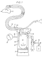
- Fig. 1 is a schematic view of a breathing apparatus, and
- Fig. 2 is an elementary view of a pneumatic control unit for controlling the breathing apparatus shown in Fig. 1.
- In Fig. 1 there is shown a breathing apparatus for controlling breathing gas to a patient, especially a narcosis apparatus for so called partial rebreathing without C02 absorption of the type Mapleson D comprising a rigid container forming a
pressure chamber 2, an excess valve 3 comprising anelastic breathing bag 8 provided therein and a flexiblecoaxial tube 4 provided between the patient (not shown) and the breathing apparatus. For controlling the gas flow to and from the patient, that is the control of the gas pressure and the breathing rate, a pneumatic control unit 5 (see Fig. 2) is provided and is connected to theinner space 2a of thepressure chamber 2 via an operating unit, i.e. an injector 6. Thepressure chamber 2 is provided with a moveable bottom 7 for adjusting the volume of thespace 2a. By this the volume of the breathing gas, i.e. the tidal volume, in the excess valve 3 can be predetermined or can be controlled. The tidal volume can for example amount to 1.000 ml for adults and 400 ml for children. For supervision and control of the working pressure, i.e. the insufflation pressure, prevailing in theinner space 2a of thepressure chamber 2 a pneumatic manometer is provided which via aconduit 10 is connected to thepressure chamber 2. Fresh gas, consisting for example of anaesthetic gas mixed with oxygen or air, is supplied to the patient via the central tube 4b of thecoaxial tube 4, theouter part 4a of which being in communication with thefirst space 11 of the excess valve 3 which is enclosed by theelastic breathing bag 8 made for example of rubber. Abreathing mask 12 preferably made of electrically conducting rubber is provided in the other end of thecoaxial tube 4. - Besides a
first space 11 the excess valve 3 is provided with a second space 13 communicating with the atmosphere via an exhausting device. By the construction of the excess valve 3 with thebreathing bag 8 applied outside thesidewall 14 of the second space 13 in which wall openings (not shown) are provided, the breathing out air from the patient to saidfirst space 11 can be passed off to said second space 13 and the further out into the atmosphere via an exhausting device. Thebreathing bag 8 expands when the gas pressure increases from the inside thereof and when this pressure has become sufficiently large thebreathing bag 8 loses its sealing effect against thesidewall 14 of said second space 13, the openings being free and the breathing air being able to pass from theinner space 11 of thebreathing bag 8 to the second space 13 of the excess valve (confer the dotted lines in Fig. 1). - By supplying compressed air via a
pneumatic conduit 15 by an injector 6 to thepressure chamber 2 a stream of air flows from the surrounding atmosphere into thepressure chamber 2, a positive pressure being formed in theinner space 2a of the pressure chamber. This working pressure or this insufflation pressure compresses thebreathing bag 8, its contents of breathing gas being pressed back to the patient via thecoaxial tube 4. The gas supplied in this way to the patient has an appropriate temperature and humidity while it is admixed with anaesthetic gas and oxygen which is supplied closed to thebreathing mask 12 via the inner tube 4b. This inner tube 4b is for example connected to an adjustable gas mixture apparatus (not shown) or to a gas output provided close to the breathing apparatus. - For controlling the insufflation pressure the pneumatic control unit 5 is provided to supply the injector 6 with gas under pressure. The pneumatic control unit 5 comprises a first and a second pneumatically controlled
main valve second volume way valve 22 which can be manually actuated. Compressed air is supplied to theinput 23 of the control unit 5, and passes the twoway valve 22 by which the control unit 5 is turned on and off. A first throttle valve 18a permits a basic flow of air to pass from thefeedline 24 to thebackline 25 and creates a basic pressure at theoutput 26 of the control unit 5 which is the PEEP (Positive Endexpiratory Pressure). Through asecond throttle valve 18b the working pressure or the insufflation pressure is set or adjusted whichthrottle valve 18b thus delimits the pressure of the air supplied via theoutput 26 to the injector 6. Besides the first throttle valve 18a the first and the secondmain valves line 24 of the control unit 5. The firstmain valve 16 is normally closed and the secondmain valve 17 is normally opened. A first and asecond volume control connections main valves throttle valves 18c, 18d connected in parallel with thenon-return valves 21b, 21c until themain valves main valves - The pneumatic unit 5 operates in a cyclic way with an inspiration phase and an expiration phase. Their lengths can be adjusted independent of each other via the
throttle valves 18d and 18c respectively. A proper breathing rate in using a partial rebreathing system without COZ-absorption is thirteen breaths per minute and this basic level is marked at thethrottle valves 18c, 18d (not shown). Compressed air is thus fed via theinput 23 to the two-way valve 22 which in its actuated position permits the air to pass further into theconduit 24. The othermain valve 17 which in this phase, i.e. the expiration phase, is open permits air to pass to thefirst volume 19 via thethrottle valve 18c. When the required reversing pressure has been achieved in thevolume 19 the firstmain valve 16 is actuated, air flowing into theconduit 25 and further via thenon-return valve 21a and thethrottle valve 18b to the output of the control unit 5. After that the inspiration phase begins. Theother volume 20 is supplied with compressed air via theconduit 25 and the throttle valve 18d. When the required reversing pressure has been achieved the othermain valve 17 is actuated and the pressure of thefirst volume 19 is unloaded via the non-return valve 21 b. This results in the fact that the firstmain valve 16 is reset to its inactivated position and the expiration phase begins again. In theother volume 20 the pressure is now reduced via thenon-return valve 21 c as a result of the fact that the pressure at theoutput 26 of the control unit 5 is lower than the pressure in thevolume 20. This procedure is repeated in a cyclic way as long as the two-way valve 22 is open. - The invention is not restricted to the example of the embodiment described above but several alternative embodiments are possible within the scope of the claims.
Claims (1)
- A breathing apparatus for administration of breathing gas in for example surgical operations, in which the breathing gases from a patient are instantaneously stored in an elastic breathing bag (8), the bag (8) being provided in a rigid pressure chamber (2), the inner space (2a) of which being adjustable in relation to its volume, whereby a pneumatic control unit (5) is provided to control the insufflation pressure in the pressure chamber (2) intermittently and via an injector (6), characterised in that, the control unit (5) comprises a first main valve (16) pneumatically controlled by a second main valve (17) via a first storage volume (19) and a first adjustable throttle valve (18c) which is connected in parallel to a non-return valve (21 b), and the second main valve (17) pneumatically controlled by the first main valve (16) via a second storage volume (20) and a second adjustable throttle valve (18d) which is connected in parallel to a second non-return valve (21c), further characterised in that the first main valve (16) is connected to the injector (6) via a third throttle valve (18b) and characterised in that the first throttle valve (18c) and the first storage volume (19) are provided to control the length of the inspiration phase, whereas the second throttle valve (17) and the second storage volume (20) are provided to control the length of the expiration phase.
Priority Applications (1)
| Application Number | Priority Date | Filing Date | Title |
|---|---|---|---|
| AT82850133T ATE22397T1 (en) | 1981-06-12 | 1982-06-11 | PNEUMATIC CONTROL UNIT FOR A RESPIRATOR. |
Applications Claiming Priority (2)
| Application Number | Priority Date | Filing Date | Title |
|---|---|---|---|
| SE8103695 | 1981-06-12 | ||
| SE8103695A SE434459B (en) | 1981-06-12 | 1981-06-12 | PNEUMATIC CONTROLLER FOR A RESPIRATORY DEVICE FOR RESPIRATORY DOSAGE |
Publications (2)
| Publication Number | Publication Date |
|---|---|
| EP0067803A1 EP0067803A1 (en) | 1982-12-22 |
| EP0067803B1 true EP0067803B1 (en) | 1986-09-24 |
Family
ID=20344048
Family Applications (1)
| Application Number | Title | Priority Date | Filing Date |
|---|---|---|---|
| EP82850133A Expired EP0067803B1 (en) | 1981-06-12 | 1982-06-11 | Pneumatic control unit for breathing apparatus |
Country Status (4)
| Country | Link |
|---|---|
| EP (1) | EP0067803B1 (en) |
| AT (1) | ATE22397T1 (en) |
| DE (1) | DE3273427D1 (en) |
| SE (1) | SE434459B (en) |
Family Cites Families (3)
| Publication number | Priority date | Publication date | Assignee | Title |
|---|---|---|---|---|
| DE929637C (en) * | 1953-04-04 | 1955-06-30 | Draegerwerk Ag | Device for artificial respiration, preferably for anesthetic purposes |
| US3621842A (en) * | 1969-07-03 | 1971-11-23 | Blease Medical Equipment Ltd | Ventilating machine |
| DE2735555C2 (en) * | 1977-08-06 | 1982-09-09 | Drägerwerk AG, 2400 Lübeck | Ventilator for emergency care |
-
1981
- 1981-06-12 SE SE8103695A patent/SE434459B/en not_active IP Right Cessation
-
1982
- 1982-06-11 EP EP82850133A patent/EP0067803B1/en not_active Expired
- 1982-06-11 DE DE8282850133T patent/DE3273427D1/en not_active Expired
- 1982-06-11 AT AT82850133T patent/ATE22397T1/en active
Also Published As
| Publication number | Publication date |
|---|---|
| SE434459B (en) | 1984-07-30 |
| ATE22397T1 (en) | 1986-10-15 |
| EP0067803A1 (en) | 1982-12-22 |
| SE8103695L (en) | 1982-12-13 |
| DE3273427D1 (en) | 1986-10-30 |
Similar Documents
| Publication | Publication Date | Title |
|---|---|---|
| US4637386A (en) | Ventilation system having true valve control for controlling ventilation pressures | |
| US4596247A (en) | Respirator | |
| US4543951A (en) | Respirator with two jet gas injection tubes | |
| US5165398A (en) | Ventilator and oscillator for use therewith and method | |
| US4067328A (en) | Lung ventilator | |
| EP0796119B1 (en) | Respirator | |
| US5398675A (en) | Anesthesia rebreathing system | |
| US4249528A (en) | Manual respirator apparatus for use with automatic respirators | |
| US3537448A (en) | Therapeutic intermittent positive pressure respirator | |
| US4120300A (en) | Breathing apparatus | |
| US4267827A (en) | Ventilator apparatus for life-support and lung scan | |
| EP0691137A2 (en) | Gas mixing devices for resuscitation/lung ventilation apparatus | |
| US3964476A (en) | Respiration system and device | |
| CA2402053C (en) | Apparatus for administering a gas to a person or an animal | |
| US4232666A (en) | Medical breathing apparatus | |
| US4508117A (en) | Apparatus for artificial pulmonary ventilation during anaesthesia and resuscitation | |
| EP0917883B1 (en) | Gas pressure generator for a ventilator | |
| US3621842A (en) | Ventilating machine | |
| EP0097060A2 (en) | Improvements in or relating to respiratory apparatus | |
| US4595004A (en) | Apparatus for the treatment of the lungs of humans or animals | |
| EP0067803A1 (en) | Pneumatic control unit for breathing apparatus | |
| EP0047185A2 (en) | Anaesthetic system | |
| US3527555A (en) | Breathing apparatus | |
| US3548821A (en) | Apparatus for artificial ventilation of lungs | |
| US3077191A (en) | Anesthetizing and resuscitating apparatus |
Legal Events
| Date | Code | Title | Description |
|---|---|---|---|
| PUAI | Public reference made under article 153(3) epc to a published international application that has entered the european phase |
Free format text: ORIGINAL CODE: 0009012 |
|
| AK | Designated contracting states |
Designated state(s): AT BE CH DE FR GB IT LI LU NL |
|
| 17P | Request for examination filed |
Effective date: 19830624 |
|
| D17P | Request for examination filed (deleted) | ||
| R17P | Request for examination filed (corrected) |
Effective date: 19830622 |
|
| R17P | Request for examination filed (corrected) |
Effective date: 19830624 |
|
| GRAA | (expected) grant |
Free format text: ORIGINAL CODE: 0009210 |
|
| AK | Designated contracting states |
Kind code of ref document: B1 Designated state(s): AT BE CH DE FR GB IT LI LU NL |
|
| PG25 | Lapsed in a contracting state [announced via postgrant information from national office to epo] |
Ref country code: LI Effective date: 19860924 Ref country code: CH Effective date: 19860924 Ref country code: BE Effective date: 19860924 Ref country code: AT Effective date: 19860924 |
|
| REF | Corresponds to: |
Ref document number: 22397 Country of ref document: AT Date of ref document: 19861015 Kind code of ref document: T |
|
| REF | Corresponds to: |
Ref document number: 3273427 Country of ref document: DE Date of ref document: 19861030 |
|
| ITF | It: translation for a ep patent filed | ||
| REG | Reference to a national code |
Ref country code: CH Ref legal event code: PL |
|
| ET | Fr: translation filed | ||
| PG25 | Lapsed in a contracting state [announced via postgrant information from national office to epo] |
Ref country code: LU Free format text: LAPSE BECAUSE OF NON-PAYMENT OF DUE FEES Effective date: 19870630 |
|
| PGFP | Annual fee paid to national office [announced via postgrant information from national office to epo] |
Ref country code: NL Payment date: 19870630 Year of fee payment: 6 |
|
| PLBE | No opposition filed within time limit |
Free format text: ORIGINAL CODE: 0009261 |
|
| STAA | Information on the status of an ep patent application or granted ep patent |
Free format text: STATUS: NO OPPOSITION FILED WITHIN TIME LIMIT |
|
| 26N | No opposition filed | ||
| PG25 | Lapsed in a contracting state [announced via postgrant information from national office to epo] |
Ref country code: GB Effective date: 19880611 |
|
| PG25 | Lapsed in a contracting state [announced via postgrant information from national office to epo] |
Ref country code: NL Effective date: 19890101 |
|
| NLV4 | Nl: lapsed or anulled due to non-payment of the annual fee | ||
| GBPC | Gb: european patent ceased through non-payment of renewal fee | ||
| PG25 | Lapsed in a contracting state [announced via postgrant information from national office to epo] |
Ref country code: FR Free format text: LAPSE BECAUSE OF NON-PAYMENT OF DUE FEES Effective date: 19890228 |
|
| PG25 | Lapsed in a contracting state [announced via postgrant information from national office to epo] |
Ref country code: DE Effective date: 19890301 |
|
| REG | Reference to a national code |
Ref country code: FR Ref legal event code: ST |