EP0067572B1 - A power assisted steering gear assembly - Google Patents
A power assisted steering gear assembly Download PDFInfo
- Publication number
- EP0067572B1 EP0067572B1 EP82302699A EP82302699A EP0067572B1 EP 0067572 B1 EP0067572 B1 EP 0067572B1 EP 82302699 A EP82302699 A EP 82302699A EP 82302699 A EP82302699 A EP 82302699A EP 0067572 B1 EP0067572 B1 EP 0067572B1
- Authority
- EP
- European Patent Office
- Prior art keywords
- driving member
- steering input
- rotation
- spring
- valve
- Prior art date
- Legal status (The legal status is an assumption and is not a legal conclusion. Google has not performed a legal analysis and makes no representation as to the accuracy of the status listed.)
- Expired
Links
- 230000005540 biological transmission Effects 0.000 claims description 26
- 230000007935 neutral effect Effects 0.000 claims description 21
- 239000012530 fluid Substances 0.000 claims description 15
- 230000033001 locomotion Effects 0.000 claims description 12
- 238000006073 displacement reaction Methods 0.000 claims description 5
- 230000000694 effects Effects 0.000 claims description 4
- 230000002093 peripheral effect Effects 0.000 claims description 2
- 230000000717 retained effect Effects 0.000 claims description 2
- 230000008878 coupling Effects 0.000 description 4
- 238000010168 coupling process Methods 0.000 description 4
- 238000005859 coupling reaction Methods 0.000 description 4
- 240000007817 Olea europaea Species 0.000 description 3
- 238000004891 communication Methods 0.000 description 2
- 238000010276 construction Methods 0.000 description 1
- 238000000034 method Methods 0.000 description 1
- 230000035945 sensitivity Effects 0.000 description 1
- 239000007787 solid Substances 0.000 description 1
Images

Classifications
-
- B—PERFORMING OPERATIONS; TRANSPORTING
- B62—LAND VEHICLES FOR TRAVELLING OTHERWISE THAN ON RAILS
- B62D—MOTOR VEHICLES; TRAILERS
- B62D5/00—Power-assisted or power-driven steering
- B62D5/06—Power-assisted or power-driven steering fluid, i.e. using a pressurised fluid for most or all the force required for steering a vehicle
- B62D5/20—Power-assisted or power-driven steering fluid, i.e. using a pressurised fluid for most or all the force required for steering a vehicle specially adapted for particular type of steering gear or particular application
- B62D5/22—Power-assisted or power-driven steering fluid, i.e. using a pressurised fluid for most or all the force required for steering a vehicle specially adapted for particular type of steering gear or particular application for rack-and-pinion type
-
- B—PERFORMING OPERATIONS; TRANSPORTING
- B62—LAND VEHICLES FOR TRAVELLING OTHERWISE THAN ON RAILS
- B62D—MOTOR VEHICLES; TRAILERS
- B62D5/00—Power-assisted or power-driven steering
- B62D5/06—Power-assisted or power-driven steering fluid, i.e. using a pressurised fluid for most or all the force required for steering a vehicle
- B62D5/08—Power-assisted or power-driven steering fluid, i.e. using a pressurised fluid for most or all the force required for steering a vehicle characterised by type of steering valve used
- B62D5/083—Rotary valves
-
- F—MECHANICAL ENGINEERING; LIGHTING; HEATING; WEAPONS; BLASTING
- F16—ENGINEERING ELEMENTS AND UNITS; GENERAL MEASURES FOR PRODUCING AND MAINTAINING EFFECTIVE FUNCTIONING OF MACHINES OR INSTALLATIONS; THERMAL INSULATION IN GENERAL
- F16D—COUPLINGS FOR TRANSMITTING ROTATION; CLUTCHES; BRAKES
- F16D3/00—Yielding couplings, i.e. with means permitting movement between the connected parts during the drive
- F16D3/02—Yielding couplings, i.e. with means permitting movement between the connected parts during the drive adapted to specific functions
-
- Y—GENERAL TAGGING OF NEW TECHNOLOGICAL DEVELOPMENTS; GENERAL TAGGING OF CROSS-SECTIONAL TECHNOLOGIES SPANNING OVER SEVERAL SECTIONS OF THE IPC; TECHNICAL SUBJECTS COVERED BY FORMER USPC CROSS-REFERENCE ART COLLECTIONS [XRACs] AND DIGESTS
- Y10—TECHNICAL SUBJECTS COVERED BY FORMER USPC
- Y10T—TECHNICAL SUBJECTS COVERED BY FORMER US CLASSIFICATION
- Y10T137/00—Fluid handling
- Y10T137/8593—Systems
- Y10T137/86493—Multi-way valve unit
- Y10T137/86574—Supply and exhaust
- Y10T137/86638—Rotary valve
- Y10T137/86646—Plug type
- Y10T137/86662—Axial and radial flow
Definitions
- This invention relates to a power-assisted steering gear assembly and is particularly concerned with such an assembly in which the valve means for controlling the flow of pressurised fluid to the power-assistance means is located at a position remote from a steering input of the assembly, as defined in the preamble of claim 1 and known for example from GB.A.1234032.
- valves for power assisted steering gear for two members of the valve to be biased by spring means to a neutral condition and for such members to be displaced against the biasing in response to a steering input to provide appropriate control of pressurised fluid for power assistance.
- a conventional form of biasing for rotary valves is a torsion bar.
- a torsion bar is extended to accommodate a rotary valve arrangement located at a position remote from the steering input, it has been found that the rotation of the torsion bar at the steering input end is not reflected to any great extent at the valve end because of the length of the torsion bar through which the twisting has to be transmitted and as a consequence the valve may have a relatively poor sensitivity or response to a steering input.
- a power-assisted steering gear assembly comprising a tubular driving member which is axially rotatable, a driven member which co-operates with the driving member to be displaced in response to rotation of the driving member to provide a steering output; fluid pressure operated means associated with the driven member and adapted to provide power assistance to displacement of the driven member with rotation of the driving member; rotary valve means adapted to control distribution of said fluid to the power assistance means, the rotary valve means comprising two valve members which are co-axial with the driving member and with a steering input, are on the axial side of said driving member remote from the steering input and are axially rotatable relative to one another from a neutral condition to effect said control, a first of the valve members being coupled for rotation with the driving member and a second of the valve members being coupled for rotation with the steering input by way of a transmission member which extends axially through the tubular driving member, and spring means- which resiliently couples the transmission member to the driving member, said spring means biasing the driving member and
- a lost motion device may be provided between the steering input and the driving member.
- the lost motion device may take any one of the known forms of such devices, according to a preferred embodiment it comprises one or more roller members mounted for axial rotation with one of the steering input and the driving member and engaging in a circumferentially extended recess in the other of the steering input and the driving member.
- the steering input and driving member should be arranged with the or each roller member located centrally in its circumferentially extended recess, and adjustment means described hereinafter may be provided to ensure such arrangement.
- the resilient coupling between the transmission member and the driving member is conveniently, but not essentially, located on the steering input side of the driving member, and, where the aforementioned lost motion device is provided, adjacent such device.
- the valve means As the valve means is located at a position remote from the steering input, difficulty may arise in centralising the valve means so that the valve members are in their neutral condition when the driving member and transmission member are in the relative rotational position to which they are biased by the spring means of the resilient coupling.
- This difficulty may be alleviated by the provision of the aforementioned adjustment means by which the relative angular positions of the transmission member and driving member may be varied without effecting the resilient coupling.
- the transmission member is rotationally rigid in use with a steering input member, as aforedescribed, which receives, for example, a steering shaft from the vehicle cab, but in order to centralise the valve members, the transmission member may be selectively angularly adjusted relative to the steering input member. Such adjustment may be provided by means of an olive and locking bush.
- the steering gear assembly shown in Figure 1 includes a longitudinally displaceable driven member in the form of a rack bar 1 which is located within a housing 2. Also located within the housing 2 is an axially rotatable driving member in the form of a pinion 3 whose teeth are in meshing engagement with teeth on the rack bar to transmit steering motion from a steering wheel (not shown) connected to a steering input member 4 of the assembly to wheels or other displacement members (not shown) connected in known manner to the rack bar 1.
- the rack bar 1 is urged into engagement with the pinion 3 by biasing means 5.
- Longitudinal displacement of the rack bar 1 by rotation of the input member 4 is intended to be power assisted by means (not shown) which is controlled by a valve 6 mounted on the housing 2.
- the steering input member 4 and valve 6 are axially aligned with the pinions 3 on opposite sides thereof.
- Valve 6 comprises a valve housing 7 rigidly connected with the housing 2 by means, not shown, such as bolts and within which radially inner and outer valve members 8 and 9, respectively, are supported for axial rotation relative to each other and to the valve housing 7.
- Valve housing 7 has two ports 10 and 11 provided therein which are adapted to transmit the pressurised fluid to the power assistance means, usually to the opposite sides of a power assistance ram.
- a third port (not shown) is adapted to receive fluid under pressure from a source (not shown).
- the neutral condition fluid communication through the valve 6 to the ports 10 and 11 is open (i.e. the valve is open centre) so that fluid is circulated without effect through the valve 6 and the power assistance means.
- valve members 8 and 9 will be in the neutral condition when power assistance is not needed, i.e. when there is no steering input to the assembly. Relative rotation of the valve members 8 and 9 out of the neutral condition opens fluid communication through the valve 6 between the appropriate port 10 or 11 to supply fluid under pressure to the power assistance means whilst closing the other port 11 or 10 respectively whereby power assistance is provided to the steering gear assembly.
- Rotary valves capable of performing this function are known per se and will not be described hereinafter in further detail. It will be appreciated however, that while the valve 6 illustrated in Figure 1 is of the open-centre type in which fluid flow through the valve in the neutral condition is free flowing, a closed valve could be used.
- Inner valve member 8 is connected by means of a pin 12 with one end 13 of a torsionally rigid axially extending transmission member 14.
- the other end 15 of the transmission member 14 is rotationally rigidly coupled with the steering input member 4 whereby rotation of the steering wheel and thereby of the input member 4 is accurately unreflected in the inner valve member 8.
- Pinion 3 is of tubular form and the transmission member 14 extends co-axially therethrough, with an 0- ring seal 16 provided between an extension portion 17 of the pinion 3 and the transmission member 14 adjacent said one end 13.
- the transmission member 14 is of regular cross-section, preferably circular, and although shown as solid could be of tubular or other construction.
- Outer valve member 9 is connected by means of a second pin 18 with the extension portion 17 of the pinion 3 whereby rotation of the pinion 3 is accurately reflected in the outer valve member 9.
- the pinion 3 and transmission member 14 resiliently coupled to each other to provide the relative rotation of the valve members 8 and 9 out of their neutral condition on rotation of the steering input member 4 and to bias the valve members 8 and 9 into their neutral condition when steering motion at the input member 4 is stopped.
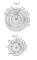
- the biasing effect is provided by spring means in the form of a C-spring 19 which is located in an annular recess 20 in the pinion shaft 21 (see also Figure 2).
- the C-spring 19 is shown in the form of three circlips arranged side-by-side but may take other forms.
- the ends of the C-spring 19 abut opposed flats 22 and 23 carried by both the pinion shaft 21 and the steering input member 4 with which the transmission member 14 is rotationally rigid, the opposed flats 22 carried by the pinion shaft 21 being provided on a pin 24 located in a radially extending bore 25 in the shaft 21, and the opposed flat 23 carried by the input member 4 being provided on a pin 26 located in an axially extending bore 27 in the member 4.
- adjustment means 28 by which the transmission member 14 may be angularly adjusted relative to the steering input member 4.
- the adjustment means 28 comprises a locking bush 29 which extends around the end 15 of the transmission member 14 and screw-threadedly engages a recess 30 in the axially outer end of the steering input member 4.
- Also provided in the recess 30 and extending around the transmission member 14 is an olive 31 and by screwing the bush 29 against the olive 31, the transmission member 14 is rigidly secured against rotation relative to the steering input member 4.
- the transmission member 14 may be rotated, using the screwdriver slot 32, relative to the input member 4 to relatively rotate the valve members 8 and 9 without adjusting the condition of the C-spring 19. After adjustment the bush 29 should be re-tightened.
- the pinion 3 is supported for rotation by a ball bearing assembly 33 at the valve-end thereof and the outer race of the assembly 33 engages both the main housing 2 and the valve housing 7.
- a fluid seal 34 is provided between the valve housing 7 and the extension portion 17 of the pinion.
- the pinion 3 is also supported for rotation by a plain bearing 35 between the pinion shaft 21 and the main housing 2, while the steering input member 4 is supported relative to the main housing 2 by a further ball bearing assembly 36.
- a seal 37 is provided between the housing 2 and input member 4.
- a roller arrangement 38 between the pinion shaft 21 and steering input member 4 may provide some support for the pinion 3 but has a main function to provide lost motion whereby the input member 4 may rotate a small amount before the pinion shaft 21 is caused to rotate.
- the roller arrangement 38 alleviates the possibility of the C-spring 19 being overstressed.
- the roller arrangement 38 (shown in Figures 1 and 3) comprises three circumferentially-spaced, part-cylindrical recesses 39 in the radially inner wall of an annular flange 40 of the steering input member 4 and respective cylindrical rollers 41 located in the recesses 39.
- Provided in the radially outer wall of the pinions shaft 21 are three co-operating circumferentially-extended recesses 42 with which respective rollers 41 engage.
- the circumferentially-extended recesses 42 permit initial rotation of the steering input member 4 relative to the pinion shaft 21 until the rollers 41 engage the one or other of the end-walls 43 (in the direction of rotation of the input member 4) of the recesses 42.
- the rollers 41 should be located centrally in the recesses 42 when the valve members are in their neutral condition.
- the recesses 39 and 42 are formed as rebates which open axially in opposite directions.
Landscapes
- Engineering & Computer Science (AREA)
- Mechanical Engineering (AREA)
- General Engineering & Computer Science (AREA)
- Chemical & Material Sciences (AREA)
- Combustion & Propulsion (AREA)
- Transportation (AREA)
- Power Steering Mechanism (AREA)
Description
- This invention relates to a power-assisted steering gear assembly and is particularly concerned with such an assembly in which the valve means for controlling the flow of pressurised fluid to the power-assistance means is located at a position remote from a steering input of the assembly, as defined in the preamble of claim 1 and known for example from GB.A.1234032.
- With the advent of transverse engines and front wheel drives in motor vehicles, various problems have arisen, one of which is that there is less space available in the area within the engine compartment that has in the past been reserved for the steering gear assembly. One solution to this problem has been to move the steering gear rearwardly, but this can mean that in a vehicle fitted with power-assisted steering gear, the hydraulic control valve is located within the cab or passenger compartment. This arrangement has clear disadvantages and it has been proposed, for example in our GB-A-1234032 and GB-A-1588593 to provide an hydraulic control valve at a position remote from the steering input to the steering gear assembly. Thus, in the case of a rack and pinion gear, it has been proposed to locate the power assistance control valve on the side of the pinion remote from the steering input with the valve being controlled by a rod in response to rotation of the steering input. This is an advantageous technique for providing additional space rearwardly of the rack bar.
- It is established practice with valves for power assisted steering gear for two members of the valve to be biased by spring means to a neutral condition and for such members to be displaced against the biasing in response to a steering input to provide appropriate control of pressurised fluid for power assistance. A conventional form of biasing for rotary valves is a torsion bar. However, if a torsion bar is extended to accommodate a rotary valve arrangement located at a position remote from the steering input, it has been found that the rotation of the torsion bar at the steering input end is not reflected to any great extent at the valve end because of the length of the torsion bar through which the twisting has to be transmitted and as a consequence the valve may have a relatively poor sensitivity or response to a steering input. To alleviate this it has been proposed in our GB-A-1234032 for the rotary valve members to be biased to their neutral condition through an axial rod from a spring structure comprising a complex assembly of tubular resilient cushioning elements which deform in response to a steering input to provide the appropriate biasing.
- It has also been proposed with power assisted steering gears having axial valves for two valve members to be axially displaceable relative to each other to provide appropriate fluid flow for power assistance through movement of an axial rod which is spring biased to a neutral condition of the valve. Such a proposal is disclosed in our GB-A-1588593 where the spring biasing is provided by two centralising wire coil springs which are fitted as a relatively complex assembly concentric with the axial rod so that, in response to a steering input, one coil spring winds up and the other opens out as appropriate to provide the required biasing.
- It is an object of the present invention to provide a power assisted steering gear assembly having a rotary valve located at a position remote from the steering input and in which rotary members of the valve are biased to a neutral condition by an efficient and compact spring arrangement which may be easily assembled to alleviate the disadvantages of the prior proposals mentioned above.
- According to the present invention there is provided a power-assisted steering gear assembly comprising a tubular driving member which is axially rotatable, a driven member which co-operates with the driving member to be displaced in response to rotation of the driving member to provide a steering output; fluid pressure operated means associated with the driven member and adapted to provide power assistance to displacement of the driven member with rotation of the driving member; rotary valve means adapted to control distribution of said fluid to the power assistance means, the rotary valve means comprising two valve members which are co-axial with the driving member and with a steering input, are on the axial side of said driving member remote from the steering input and are axially rotatable relative to one another from a neutral condition to effect said control, a first of the valve members being coupled for rotation with the driving member and a second of the valve members being coupled for rotation with the steering input by way of a transmission member which extends axially through the tubular driving member, and spring means- which resiliently couples the transmission member to the driving member, said spring means biasing the driving member and transmission member rotationally relative to each other and thereby rotationally biasing the two valve members to said neutral condition, and wherein the driving member extends axially within a recess formed by an annular flange of the steering input characterised in that the driving member has a peri- - pheral recess within which is located the spring means comprising a C-spring which is axially retained by the recess on, and encircles, the driving member, said C-spring having a radially extending mouth within which extends a radially extending pin rotatable with the driving member and, radially outwardly of said radially extending pin, an axially extending pin rotatable with the steering input so that during relative rotation between the driving member and steering input the radial and axial pins respectively abut the C-spring within and on opposite sides of the mouth thereof to enlarge said mouth and cause the C-spring to bias the valve members to the neutral condition.
- To alleviate overstressing of the spring means of the resilient coupling, a lost motion device may be provided between the steering input and the driving member. While the lost motion device may take any one of the known forms of such devices, according to a preferred embodiment it comprises one or more roller members mounted for axial rotation with one of the steering input and the driving member and engaging in a circumferentially extended recess in the other of the steering input and the driving member. When the valve members are in their neutral condition, the steering input and driving member should be arranged with the or each roller member located centrally in its circumferentially extended recess, and adjustment means described hereinafter may be provided to ensure such arrangement.
- The resilient coupling between the transmission member and the driving member is conveniently, but not essentially, located on the steering input side of the driving member, and, where the aforementioned lost motion device is provided, adjacent such device.
- As the valve means is located at a position remote from the steering input, difficulty may arise in centralising the valve means so that the valve members are in their neutral condition when the driving member and transmission member are in the relative rotational position to which they are biased by the spring means of the resilient coupling. This difficulty may be alleviated by the provision of the aforementioned adjustment means by which the relative angular positions of the transmission member and driving member may be varied without effecting the resilient coupling. Preferably, the transmission member is rotationally rigid in use with a steering input member, as aforedescribed, which receives, for example, a steering shaft from the vehicle cab, but in order to centralise the valve members, the transmission member may be selectively angularly adjusted relative to the steering input member. Such adjustment may be provided by means of an olive and locking bush.
- One embodiment of a power-assisted steering gear assembly in accordance with the present invention will now be described by way of example only, with reference to the accompanying illustrative drawings, in which:
- FIGURE 1 is a cross-sectional view of the assembly generally along the pinion axis;
- FIGURE 2 is a sectional view taken on the line A-A of Figure 1, and
- FIGURE 3 is a sectional view taken on the line B-B of Figure 1.
- The steering gear assembly shown in Figure 1 includes a longitudinally displaceable driven member in the form of a rack bar 1 which is located within a housing 2. Also located within the housing 2 is an axially rotatable driving member in the form of a pinion 3 whose teeth are in meshing engagement with teeth on the rack bar to transmit steering motion from a steering wheel (not shown) connected to a steering input member 4 of the assembly to wheels or other displacement members (not shown) connected in known manner to the rack bar 1. The rack bar 1 is urged into engagement with the pinion 3 by
biasing means 5. Longitudinal displacement of the rack bar 1 by rotation of the input member 4 is intended to be power assisted by means (not shown) which is controlled by a valve 6 mounted on the housing 2. The steering input member 4 and valve 6 are axially aligned with the pinions 3 on opposite sides thereof. - Valve 6 comprises a valve housing 7 rigidly connected with the housing 2 by means, not shown, such as bolts and within which radially inner and outer valve members 8 and 9, respectively, are supported for axial rotation relative to each other and to the valve housing 7. Valve housing 7 has two
ports 10 and 11 provided therein which are adapted to transmit the pressurised fluid to the power assistance means, usually to the opposite sides of a power assistance ram. A third port (not shown) is adapted to receive fluid under pressure from a source (not shown). In a preset angular relationship of the valve members 8 and 9 to each other, the neutral condition, fluid communication through the valve 6 to theports 10 and 11 is open (i.e. the valve is open centre) so that fluid is circulated without effect through the valve 6 and the power assistance means. The valve members 8 and 9 will be in the neutral condition when power assistance is not needed, i.e. when there is no steering input to the assembly. Relative rotation of the valve members 8 and 9 out of the neutral condition opens fluid communication through the valve 6 between theappropriate port 10 or 11 to supply fluid under pressure to the power assistance means whilst closing theother port 11 or 10 respectively whereby power assistance is provided to the steering gear assembly. Rotary valves capable of performing this function are known per se and will not be described hereinafter in further detail. It will be appreciated however, that while the valve 6 illustrated in Figure 1 is of the open-centre type in which fluid flow through the valve in the neutral condition is free flowing, a closed valve could be used. - Relative rotation of the valve members 8 and 9 is provided for in the following manner. Inner valve member 8 is connected by means of a pin 12 with one end 13 of a torsionally rigid axially extending
transmission member 14. The other end 15 of thetransmission member 14 is rotationally rigidly coupled with the steering input member 4 whereby rotation of the steering wheel and thereby of the input member 4 is accurately unreflected in the inner valve member 8. Pinion 3 is of tubular form and thetransmission member 14 extends co-axially therethrough, with an 0-ring seal 16 provided between an extension portion 17 of the pinion 3 and thetransmission member 14 adjacent said one end 13. Between the ends 13 and 15, thetransmission member 14 is of regular cross-section, preferably circular, and although shown as solid could be of tubular or other construction. - Outer valve member 9 is connected by means of a second pin 18 with the extension portion 17 of the pinion 3 whereby rotation of the pinion 3 is accurately reflected in the outer valve member 9. The pinion 3 and
transmission member 14 resiliently coupled to each other to provide the relative rotation of the valve members 8 and 9 out of their neutral condition on rotation of the steering input member 4 and to bias the valve members 8 and 9 into their neutral condition when steering motion at the input member 4 is stopped. - The biasing effect is provided by spring means in the form of a C-
spring 19 which is located in an annular recess 20 in the pinion shaft 21 (see also Figure 2). The C-spring 19 is shown in the form of three circlips arranged side-by-side but may take other forms. The ends of the C-spring 19 abut opposedflats pinion shaft 21 and the steering input member 4 with which thetransmission member 14 is rotationally rigid, theopposed flats 22 carried by thepinion shaft 21 being provided on apin 24 located in a radially extendingbore 25 in theshaft 21, and the opposed flat 23 carried by the input member 4 being provided on apin 26 located in anaxially extending bore 27 in the member 4. Accordingly relative rotation of the pinion 3 and input member 4 causes the C-spring to open resiliently, and if the valve members 8 and 8 are set-up so that when the C-spring is closed (i.e. when theflats - Such setting-up of the valve members 8 and 9 is provided for by adjustment means 28 by which the
transmission member 14 may be angularly adjusted relative to the steering input member 4. The adjustment means 28 comprises alocking bush 29 which extends around the end 15 of thetransmission member 14 and screw-threadedly engages a recess 30 in the axially outer end of the steering input member 4. Also provided in the recess 30 and extending around thetransmission member 14 is an olive 31 and by screwing thebush 29 against the olive 31, thetransmission member 14 is rigidly secured against rotation relative to the steering input member 4. When thebush 29 is slackened off, thetransmission member 14 may be rotated, using thescrewdriver slot 32, relative to the input member 4 to relatively rotate the valve members 8 and 9 without adjusting the condition of the C-spring 19. After adjustment thebush 29 should be re-tightened. - The pinion 3 is supported for rotation by a
ball bearing assembly 33 at the valve-end thereof and the outer race of theassembly 33 engages both the main housing 2 and the valve housing 7. Afluid seal 34 is provided between the valve housing 7 and the extension portion 17 of the pinion. The pinion 3 is also supported for rotation by a plain bearing 35 between thepinion shaft 21 and the main housing 2, while the steering input member 4 is supported relative to the main housing 2 by a furtherball bearing assembly 36. Aseal 37 is provided between the housing 2 and input member 4. - A
roller arrangement 38 between thepinion shaft 21 and steering input member 4 may provide some support for the pinion 3 but has a main function to provide lost motion whereby the input member 4 may rotate a small amount before thepinion shaft 21 is caused to rotate. Theroller arrangement 38 alleviates the possibility of the C-spring 19 being overstressed. The roller arrangement 38 (shown in Figures 1 and 3) comprises three circumferentially-spaced, part-cylindrical recesses 39 in the radially inner wall of anannular flange 40 of the steering input member 4 and respectivecylindrical rollers 41 located in therecesses 39. Provided in the radially outer wall of thepinions shaft 21 are three co-operating circumferentially-extended recesses 42 with whichrespective rollers 41 engage. The circumferentially-extended recesses 42 permit initial rotation of the steering input member 4 relative to thepinion shaft 21 until therollers 41 engage the one or other of the end-walls 43 (in the direction of rotation of the input member 4) of the recesses 42. When the valve members 8 and 9 are properly set-up as afore-described, therollers 41 should be located centrally in the recesses 42 when the valve members are in their neutral condition. For convenience of assembly therecesses 39 and 42 are formed as rebates which open axially in opposite directions.
Claims (5)
Applications Claiming Priority (2)
| Application Number | Priority Date | Filing Date | Title |
|---|---|---|---|
| GB8117028 | 1981-06-03 | ||
| GB8117028 | 1981-06-03 |
Publications (3)
| Publication Number | Publication Date |
|---|---|
| EP0067572A2 EP0067572A2 (en) | 1982-12-22 |
| EP0067572A3 EP0067572A3 (en) | 1984-05-16 |
| EP0067572B1 true EP0067572B1 (en) | 1987-08-19 |
Family
ID=10522251
Family Applications (1)
| Application Number | Title | Priority Date | Filing Date |
|---|---|---|---|
| EP82302699A Expired EP0067572B1 (en) | 1981-06-03 | 1982-05-26 | A power assisted steering gear assembly |
Country Status (3)
| Country | Link |
|---|---|
| US (1) | US4449601A (en) |
| EP (1) | EP0067572B1 (en) |
| DE (1) | DE3277008D1 (en) |
Families Citing this family (17)
| Publication number | Priority date | Publication date | Assignee | Title |
|---|---|---|---|---|
| IT1145712B (en) * | 1981-11-09 | 1986-11-05 | Corint Srl | DISTRIBUTOR VALVE FOR THE POWER TO RACK POWER STEERING CONTROL FOR VEHICLES |
| GB2109757B (en) * | 1981-11-18 | 1985-06-19 | Cam Gears Ltd | A power assisted steering gear |
| ES8402781A1 (en) * | 1983-03-22 | 1984-03-16 | Bendiberica Sa | Power steering with central output. |
| ES8404474A1 (en) * | 1983-04-26 | 1984-05-01 | Bendiberica Sa | Hydraulic rotatory distributor, particularly for a vehicle's servo steering system. |
| GB2181099B (en) * | 1983-07-19 | 1987-12-23 | Ford Motor Co | Power assisted steering gear |
| GB2179606B (en) * | 1985-08-26 | 1988-06-15 | Bishop Arthur E | Power steering gear adjusting mechanism |
| DE3634216A1 (en) * | 1985-10-21 | 1987-04-23 | Zahnradfabrik Friedrichshafen | CENTERING DEVICE FOR TWO COMPONENTS WITH TWISTABLE PARTS |
| GB2188888B (en) * | 1986-04-14 | 1989-12-06 | Trw Cam Gears Ltd | A rotary valve assembly and a method of assembling a rotary valve |
| GB2215684A (en) * | 1988-03-17 | 1989-09-27 | Trw Cam Gears Ltd | Hydraulic power assisted steering system |
| US5311906A (en) * | 1992-02-04 | 1994-05-17 | Techco Corporation | Preload mechanism for power steering apparatus |
| US5316043A (en) * | 1992-02-04 | 1994-05-31 | Techco Corporation | Preload mechanism for power steering apparatus |
| US5544522A (en) * | 1994-10-28 | 1996-08-13 | Trw Inc. | Steering assembly and method |
| US5469929A (en) * | 1995-04-03 | 1995-11-28 | General Motors Corporation | Motor vehicle power steering gear |
| US5462132A (en) * | 1995-04-14 | 1995-10-31 | General Motors Corporation | Motor vehicle power steering gear |
| DE19545513A1 (en) * | 1995-12-06 | 1997-06-26 | Liebherr Aerospace Gmbh | Coupling between rotating sections of helicopter fluid valve |
| FR2780935B1 (en) * | 1998-07-09 | 2000-09-15 | Soc D Mecanique D Irigny | METHOD FOR REDUCING TORQUE DISPERSION ON AN ASSIST VALVE FOR HYDRAULIC POWER-ASSISTED STEERING OF A MOTOR VEHICLE |
| KR101271294B1 (en) * | 2011-06-20 | 2013-06-04 | 주식회사 만도 | Rack Bar Supporting Device of Steering Apparatus for Vehicle |
Family Cites Families (6)
| Publication number | Priority date | Publication date | Assignee | Title |
|---|---|---|---|---|
| GB1234032A (en) * | 1967-08-22 | 1971-06-03 | ||
| GB1380360A (en) * | 1972-07-20 | 1975-01-15 | Cam Gears Ltd | Rack and pinion power assisted steering |
| GB1547572A (en) * | 1975-04-15 | 1979-06-20 | Bendix Westinghouse Ltd | Power assistance control device |
| GB1588593A (en) * | 1975-10-21 | 1981-04-29 | Cam Gears Ltd | Powerassisted steering gear |
| GB1603198A (en) * | 1978-04-10 | 1981-11-18 | Cam Gears Ltd | Powerassisted steering |
| FR2452409A1 (en) * | 1979-03-26 | 1980-10-24 | Ferodo Sa | POWER ASSISTED STEERING DEVICE AND MANUFACTURING METHOD THEREOF |
-
1982
- 1982-05-26 EP EP82302699A patent/EP0067572B1/en not_active Expired
- 1982-05-26 DE DE8282302699T patent/DE3277008D1/en not_active Expired
- 1982-05-28 US US06/382,816 patent/US4449601A/en not_active Expired - Lifetime
Also Published As
| Publication number | Publication date |
|---|---|
| EP0067572A3 (en) | 1984-05-16 |
| US4449601A (en) | 1984-05-22 |
| DE3277008D1 (en) | 1987-09-24 |
| EP0067572A2 (en) | 1982-12-22 |
Similar Documents
| Publication | Publication Date | Title |
|---|---|---|
| EP0067572A2 (en) | A power assisted steering gear assembly | |
| US3033051A (en) | Power steering gear | |
| US4621702A (en) | Four-wheel steering apparatus of a vehicle | |
| US3292499A (en) | Power steering gear | |
| US4784234A (en) | Motor driven power steering system | |
| JPS585826B2 (en) | Vehicle power steering system | |
| US5156228A (en) | Front wheel steering apparatus | |
| US4195706A (en) | Power steering valve system | |
| US4178835A (en) | Rotary valve for power-assisted steering mechanism | |
| US5671637A (en) | Servo-assisted rack-and-pinion system | |
| US4487225A (en) | Power assisted steering gear | |
| US4503753A (en) | Hydraulic power-assistance actuating mechanisms, especially for servo-assisted steering systems | |
| US6296018B1 (en) | Rack and pinion steering system | |
| JP3109920B2 (en) | Steering gear | |
| EP0077903B1 (en) | Hydrostatic steering system with delayed input torque column | |
| EP0336553B1 (en) | A vehicle power assisted steering system | |
| US20180237061A1 (en) | Power steering assembly comprising steering torque overlay | |
| US3669146A (en) | Power assisted steering system | |
| US4060146A (en) | Power steering mechanism | |
| US4489755A (en) | Power assisted steering gear | |
| JP4055001B2 (en) | Reduction ratio variable power steering system | |
| GB2199000A (en) | A valve assembly for a power assisted steering system | |
| US2870645A (en) | Vehicle power steering apparatus | |
| GB1603198A (en) | Powerassisted steering | |
| JP2963584B2 (en) | Steering gear |
Legal Events
| Date | Code | Title | Description |
|---|---|---|---|
| PUAI | Public reference made under article 153(3) epc to a published international application that has entered the european phase |
Free format text: ORIGINAL CODE: 0009012 |
|
| AK | Designated contracting states |
Designated state(s): DE FR GB IT SE |
|
| PUAL | Search report despatched |
Free format text: ORIGINAL CODE: 0009013 |
|
| AK | Designated contracting states |
Designated state(s): DE FR GB IT SE |
|
| 17P | Request for examination filed |
Effective date: 19840619 |
|
| RAP1 | Party data changed (applicant data changed or rights of an application transferred) |
Owner name: TRW CAM GEARS LIMITED |
|
| GRAA | (expected) grant |
Free format text: ORIGINAL CODE: 0009210 |
|
| AK | Designated contracting states |
Kind code of ref document: B1 Designated state(s): DE FR GB IT SE |
|
| ET | Fr: translation filed | ||
| REF | Corresponds to: |
Ref document number: 3277008 Country of ref document: DE Date of ref document: 19870924 |
|
| ITF | It: translation for a ep patent filed | ||
| RIN2 | Information on inventor provided after grant (corrected) |
Free format text: ADAMS, FREDERICK JOHN |
|
| PLBE | No opposition filed within time limit |
Free format text: ORIGINAL CODE: 0009261 |
|
| STAA | Information on the status of an ep patent application or granted ep patent |
Free format text: STATUS: NO OPPOSITION FILED WITHIN TIME LIMIT |
|
| 26N | No opposition filed | ||
| ITTA | It: last paid annual fee | ||
| EAL | Se: european patent in force in sweden |
Ref document number: 82302699.2 |
|
| PGFP | Annual fee paid to national office [announced via postgrant information from national office to epo] |
Ref country code: FR Payment date: 19970625 Year of fee payment: 16 |
|
| PGFP | Annual fee paid to national office [announced via postgrant information from national office to epo] |
Ref country code: SE Payment date: 19970627 Year of fee payment: 16 |
|
| PGFP | Annual fee paid to national office [announced via postgrant information from national office to epo] |
Ref country code: DE Payment date: 19970630 Year of fee payment: 16 |
|
| PGFP | Annual fee paid to national office [announced via postgrant information from national office to epo] |
Ref country code: GB Payment date: 19980518 Year of fee payment: 17 |
|
| PG25 | Lapsed in a contracting state [announced via postgrant information from national office to epo] |
Ref country code: SE Free format text: LAPSE BECAUSE OF NON-PAYMENT OF DUE FEES Effective date: 19980527 |
|
| PG25 | Lapsed in a contracting state [announced via postgrant information from national office to epo] |
Ref country code: FR Free format text: LAPSE BECAUSE OF NON-PAYMENT OF DUE FEES Effective date: 19980531 |
|
| EUG | Se: european patent has lapsed |
Ref document number: 82302699.2 |
|
| PG25 | Lapsed in a contracting state [announced via postgrant information from national office to epo] |
Ref country code: DE Free format text: LAPSE BECAUSE OF NON-PAYMENT OF DUE FEES Effective date: 19990302 |
|
| REG | Reference to a national code |
Ref country code: FR Ref legal event code: ST |
|
| PG25 | Lapsed in a contracting state [announced via postgrant information from national office to epo] |
Ref country code: GB Free format text: LAPSE BECAUSE OF NON-PAYMENT OF DUE FEES Effective date: 19990526 |
|
| GBPC | Gb: european patent ceased through non-payment of renewal fee |
Effective date: 19990526 |