EP0067107B1 - Dispositif de séparation, d'orientation et de positionnement de pièces de forme générale plate - Google Patents
Dispositif de séparation, d'orientation et de positionnement de pièces de forme générale plate Download PDFInfo
- Publication number
- EP0067107B1 EP0067107B1 EP82401018A EP82401018A EP0067107B1 EP 0067107 B1 EP0067107 B1 EP 0067107B1 EP 82401018 A EP82401018 A EP 82401018A EP 82401018 A EP82401018 A EP 82401018A EP 0067107 B1 EP0067107 B1 EP 0067107B1
- Authority
- EP
- European Patent Office
- Prior art keywords
- rocker member
- component
- rocker
- movement
- fingers
- Prior art date
- Legal status (The legal status is an assumption and is not a legal conclusion. Google has not performed a legal analysis and makes no representation as to the accuracy of the status listed.)
- Expired
Links
Images


Classifications
-
- B—PERFORMING OPERATIONS; TRANSPORTING
- B23—MACHINE TOOLS; METAL-WORKING NOT OTHERWISE PROVIDED FOR
- B23Q—DETAILS, COMPONENTS, OR ACCESSORIES FOR MACHINE TOOLS, e.g. ARRANGEMENTS FOR COPYING OR CONTROLLING; MACHINE TOOLS IN GENERAL CHARACTERISED BY THE CONSTRUCTION OF PARTICULAR DETAILS OR COMPONENTS; COMBINATIONS OR ASSOCIATIONS OF METAL-WORKING MACHINES, NOT DIRECTED TO A PARTICULAR RESULT
- B23Q7/00—Arrangements for handling work specially combined with or arranged in, or specially adapted for use in connection with, machine tools, e.g. for conveying, loading, positioning, discharging, sorting
- B23Q7/04—Arrangements for handling work specially combined with or arranged in, or specially adapted for use in connection with, machine tools, e.g. for conveying, loading, positioning, discharging, sorting by means of grippers
-
- B—PERFORMING OPERATIONS; TRANSPORTING
- B23—MACHINE TOOLS; METAL-WORKING NOT OTHERWISE PROVIDED FOR
- B23Q—DETAILS, COMPONENTS, OR ACCESSORIES FOR MACHINE TOOLS, e.g. ARRANGEMENTS FOR COPYING OR CONTROLLING; MACHINE TOOLS IN GENERAL CHARACTERISED BY THE CONSTRUCTION OF PARTICULAR DETAILS OR COMPONENTS; COMBINATIONS OR ASSOCIATIONS OF METAL-WORKING MACHINES, NOT DIRECTED TO A PARTICULAR RESULT
- B23Q7/00—Arrangements for handling work specially combined with or arranged in, or specially adapted for use in connection with, machine tools, e.g. for conveying, loading, positioning, discharging, sorting
- B23Q7/10—Arrangements for handling work specially combined with or arranged in, or specially adapted for use in connection with, machine tools, e.g. for conveying, loading, positioning, discharging, sorting by means of magazines
- B23Q7/106—Arrangements for handling work specially combined with or arranged in, or specially adapted for use in connection with, machine tools, e.g. for conveying, loading, positioning, discharging, sorting by means of magazines with means to deliver a certain quantity
Definitions
- the invention relates to the successive supply in good position and in good orientation of generally flat parts of substantially flat shape, in particular of the dog axles of gearbox shafts, for supplying an automatic machine for welding the dogs on the axes.
- the dogs are conveyed on edge in a vibrating rail to a non-vibrating bezel placed at the end of the rail and which carries a reserve of a few dogs.
- a non-vibrating bezel placed at the end of the rail and which carries a reserve of a few dogs.
- the dog placed at the end of the reserve falls a few millimeters in order to offer resistance to the workpiece carrier of the automatic machine which comes to grip it.
- the bezel has two eclipsable retainers which hold the first dog and which are overshadowed by two fingers mounted on the workpiece carrier when the latter comes to pick up the dog.
- Document GB-A No. 688533 has already proposed a device for separating, orienting and positioning parts which receives these parts, distributed in continuous file on a store rail by an auxiliary device and bringing them one by one into a orientation and a precise position to be taken up by a workpiece carrier, the device comprising a rocker actuable by a jack between a first raised position and a second tilted position, this rocker comprising a support following the store rail in the raised position of the rocker to receive the first part of the magazine, stop means stopping all the parts, this support also comprising a retaining device arranged to prevent the escape of the part on the rocker during the tilting thereof.
- the object of the invention is to propose a device of the type of that of the prior art which can be supplied with parts positioned flat on a rail, a supply much easier to produce, and which furthermore produces the separation of these parts, their tilting to orient them on edge, and their effective retention until taken up by the workpiece carrier, and finally which is of great reliability and great simplicity of realization.
- the invention provides a device characterized in that the device separates, orientates and positions pieces of substantially flat shape supplied flat on the store rail, the assembly further comprising stop keys carried by a piece tilting recalled by a return spring to stop the first part remaining on the rail during the tilting of the rocker, with a mechanism enabling these keys to be released from their active position when the rocker is in the raised position, the retaining device being mounted sliding horizontally and parallel to the support and comprising two fingers arranged so as to allow the passage of each new piece under these fingers but at the same time to be able to release the outline of the piece for a perpendicular extraction using a short stroke of the device. detention.
- the exemplary embodiment relates more particularly to the supply of an automatic welding machine with clutch dog axles of gearbox forks which are parts having the shape shown under the reference 1 in the figures. These are substantially flat parts cut and arched according to the profile visible in FIG. 2, and the installation comprises above all a vibrating bowl receiving these loose parts and positioning them in continuous flat wire on a rail.
- This assembly of conventional design has not been shown and it is much easier to produce than the usual device placing the pieces on edge.
- the parts 1 therefore arrive by pushing themselves side by side in a continuous file on a rail 2.
- the device comprises a rocker 3, capable of rocking around a horizontal axis 4 under the effect of a jack 5 to pass from the position shown in solid lines in FIG. 1 at the position shown in broken lines in this same figure.
- This rocker comprises a support constituted by parts 6 and 7 which, in the first position of the rocker, ensure the continuity of the rails 2 to receive the first place 1, with in addition a stop 8 stopping the whole succession of moving parts 1 .
- this rocker is also provided with a retaining device 9 which comprises two retaining fingers 10 and 11 arranged so that the parts 1 can pass underneath to come into abutment against the abutment 8, but that these fingers slightly cover the outline of the first part at points capable of preventing it from escaping in the subsequent rocking movement of the rocker.
- these points are also chosen according to the contour of the part so that a slight backward movement of the retaining device 9 in the direction of the arrow 11 completely releases the part to allow it to be extracted in the direction perpendicular to its own main plane.
- the device 9 as a whole is mounted sliding on the top of the rocker 3, being returned in the direction opposite to the arrow 12 by a return spring 13, and it comprises a ramp 14 inclined in the proper direction to allow by pressing on this ramp to cause the release in the direction of arrow 12.
- a retractable stop device constituted by a tilting part 16, articulated around an axis 17 and comprising two contact keys 18 and 19, which in the raised position of the part 16 come into contact with judiciously chosen points of the part 1 immediately adjacent to that which is on the support in order to stop its progression.
- the tilting part 16 is returned to the raised position by a return spring 20 and comes in this position to rest on an adjustable angular stop 21 which allows the precise adjustment of this position.
- the tilting part 16 comprises a roller 22 constituting a cam follower and cooperating with a cam 23 carried by the rocker 3 to move the stop keys 18 and 19 from their active position when the rocker 3 is very close to arriving. in its first position, as shown in solid lines in FIG. 1.
- a single cylinder 5 is sufficient to simultaneously ensure the separation of the parts of the continuous reserve, their transfer by tilting in a different and precise orientation and position, the retention of the part tilted to the recovery by the workpiece carrier, and the retention of the parts of the reserve during this tilting, all these movements being consequently synchronized by the single control of the jack 5, hydraulic or pneumatic, and the assembly being particularly simple and reliable, even with high operating rates.
Landscapes
- Engineering & Computer Science (AREA)
- Mechanical Engineering (AREA)
- Automatic Assembly (AREA)
- Specific Conveyance Elements (AREA)
- Feeding Of Articles To Conveyors (AREA)
Description
- L'invention concerne l'amenage successif en bonne position et en bonne orientation de pièces de forme générale sensiblement plate, en particulier des crabots d'axes de boîtes de vitesses, pour l'alimentation d'une machine automatique à souder les crabots sur les axes.
- Habituellement, les crabots sont véhiculés sur chant dans un rail vibrant jusqu'à un drageoir non vibrant placé en bout de rail et qui porte une réserve de quelques crabots. Périodiquement, le crabot placé en bout de la réserve tombe de quelques millimètres afin d'offrir une résistance au porte-pièce de la machine automatique qui vient le saisir. Le drageoir comporte deux retenues éclipsables qui retiennent le premier crabot et qui sont éclipsées par deux doigts montés sur le porte-pièces lorsque celui-ci vient prendre le crabot.
- Les inconvénients de cette technique sont d'abord la grande difficulté de sélectionner les pièces approvisionnées en vrac dans un bol vibrant pour pouvoir ensuite les cheminer sur chant dans le rail vibrant. Certaines formes de crabot rendent même cette sélection automatique impossible et nécessitent des techniques beaucoup plus sophistiquées. Ensuite, le dispositif est peu fiable et sujet à de nombreux coincements de sorte que les deux retenues éclipsables ne retiennent pas toujours efficacement les crabots, surtout au moment d'une prise de pièces par le porte-pièces, et de nombreux crabots tombent alors sur la plate-forme de la machine.
- On a déjà proposé dans le document GB-A No 688533 un dispositif de séparation, d'orientation et de positionnement de pièces qui reçoit ces pièces, distribuées en file continue sur un rail magasin par un dispositif auxiliaire et les amenant une par une dans une orientation et une position précises pour être reprises par un porte-pièces, le dispositif comportant un basculeur actionnable par un vérin entre une première position relevée et une deuxième position basculée, ce basculeur comportant un support faisant suite au rail magasin dans la position relevée du basculeur pour recevoir la première pièce du magasin, des moyens de butée arrêtant l'ensemble des pièces, ce support comportant également un dispositif de retenue agencé pour empêcher l'échappement de la pièce sur le basculeur pendant le basculement de celui-ci.
- Le but de l'invention est de proposer un dispositif du type de celui de l'art antérieur qui puisse être alimenté avec des pièces positionnées à plat sur un rail, alimentation beaucoup plus facile à réaliser, et qui en outre produise la séparation de ces pièces, leur basculement pour les orienter sur chant, et leur retenue efficace jusqu'à la reprise par le porte-pièces, et enfin qui soit d'une grande fiabilité et d'une grande simplicité de réalisation.
- Dans ce but, l'invention propose un dispositif caractérisé en ce que le dispositif sépare, oriente et positionne des pièces de forme sensiblement plate approvisionnées à plat sur le rail magasin, l'ensemble comportant en outre des touches d'arrêt portées par une pièce basculante rappelée par un ressort de rappel pour arrêter la première pièce restant sur le rail lors du basculement du basculeur, avec un mécanisme permettant de dégager ces touches de leur position active lorsque le basculeur est en position relevée, le dispositif de retenue étant monté coulissant horizontalement et parallèlement au support et comportant deux doigts disposés de manière à permettre le passage de chaque nouvelle pièce sous ces doigts mais en même temps à pouvoir libérer le contour de la pièce pour une extraction perpendiculaire à l'aide d'une faible course du dispositif de retenue.
- D'autres particularités de l'invention apparaîtront dans la description qui va suivre d'un mode de réalisation pris comme exemple et représenté sur le dessin annexé, sur lequel:
- la fig. 1 est une coupe verticale de l'appareil selon 1 -1 de la fig. 2;
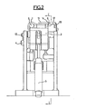
- la fig. 2 est unevue en boutselon II-II de la fig. 1;
- la fig. 3 est une vue de dessus de cet appareil.
- L'exemple de réalisation concerne plus particulièrement l'alimentation d'une machine à souder automatique en crabots d'axes de fourchettes de boîtes de vitesses qui sont des pièces ayant la forme représentée sous la référence 1 sur les figures. Il s'agit de pièces sensiblement plates découpées-cambrées selon le profil visible sur la fig. 2, et l'installation comporte avant tout un bol vibrant recevant ces pièces en vrac et les positionnant en fil continu à plat sur un rail. Cet ensemble de conception classique n'a pas été représenté et il est beaucoup plus facile à réaliser que le dispositif habituel plaçant les pièces sur chant.
- Les pièces 1 arrivent donc en se poussant côte à côte en file continue sur un rail 2.
- Le dispositif comporte un basculeur 3, susceptible de basculer autour d'un axe horizontal 4 sous l'effet d'un vérin 5 pour passer de la position représentée en trait plein sur la fig. 1 à la position représentée en trait interrompu sur cette même figure. Ce basculeur comporte un support constitué par des parties 6 et 7 qui, dans la première position du basculeur, viennent assurer la continuité des rails 2 pour recevoir la première place 1, avec en outre une butée 8 arrêtant toute la succession des pièces 1 en mouvement.
- Par ailleurs, ce basculeur est pourvu également d'un dispositif de retenue 9 qui comporte deux doigts de retenue 10 et 11 disposés de manière que les pièces 1 puissent passer en dessous pour venir en butée contre la butée 8, mais que ces doigts recouvrent légèrement le contour de la première pièce en des points susceptibles d'empêcher celle-ci de s'échapper dans le mouvement de basculement ultérieur du basculeur. En outre, ces points sont choisis également en fonction du contour de la pièce de telle manière qu'un léger mouvement de recul du dispositif de retenue 9 dans le sens de la flèche 11 libère entièrement la pièce pour lui permettre d'être extraite dans le sens perpendiculaire à son propre plan principal. Pour cela le dispositif 9 dans son ensemble est monté coulissant sur le sommet du basculeur 3, en étant rappelé dans le sens opposé à la flèche 12 par un ressort de rappel 13, et il comporte une rampe 14 inclinée dans le sens convenable pour permettre en appuyant sur cette rampe de provoquer le dégagement dans le sens de la flèche 12.
- Cela permet par conséquent au vérin d'amener le basculeur 3 de la position verticale à la position horizontale en entraînant avec lui la première pièce 1 sans que celle-ci puisse s'échapper au cours de ce mouvement. Par contre, lorsque le porte-pièces 15 faisant partie de la machine automatique de soudure vient reprendre cette pièce dans la position précise et l'orientation convenable où l'a amené le basculeur précédent, un doigt non représenté, porté par ce porte-pièces, vient agir sur la rampe 14 pour provoquer le dégagement du dispositif de retenue 9 afin de permettre au porte-pièces 15 de saisir la pièce 1 et de l'extraire dans le sens perpendiculaire au plan de la pièce, c'est-à-dire pour cette nouvelle position du basculeur dans le sens horizontal.
- Pendant tout ce mouvement de basculement et jusqu'au retour complet du basculeur dans la position initiale, il faut éviter que la succession des pièces, qui suivent la première qui vient d'être extraite, continue son mouvement et vienne tomber en désordre sur la machine.
- Pour cela, il est prévu un dispositif de butées escamotables constitué par une pièce basculante 16, articulée autour d'un axe 17 et comportant deux touches de contact 18 et 19, qui dans la position relevée de la pièce 16 viennent contacter des points judicieusement choisis de la pièce 1 immédiatement adjacente à celle qui se trouve sur le support afin d'arrêter sa progression. Pour cela, la pièce basculante 16 se trouve rappelée en position relevée par un ressort de rappel 20 et vient dans cette position s'appuyer sur une butée angulaire réglable 21 qui permet l'ajustement précis de cette position.
- Par contre, lorsque le basculeur est dans sa première position représentée sur la fig. 1, ces doigts doivent être escamotés pour permettre le libre passage des pièces 1 du rail 2 vers le support 6,7. Pour cela, la pièce basculante 16 comporte un galet 22 constituant suiveur de came et coopérant avec une came 23 portée par le basculeur 3 pour écarter les touches d'arrêt 18 et 19 de leur position active lorsque le basculeur 3 est tout près d'arriver dans sa première position, comme représenté en trait plein sur la fig. 1.
- De la sorte, un seul et même vérin 5 suffit pour assurer tout à la fois la séparation des pièces de la réserve continue, leur transfert par basculement dans une orientation et une position différentes et précises, la retenue de la pièce basculée jusqu'à la reprise par le porte-pièces, et la retenue des pièces de la réserve pendant ce basculement, tous ces mouvements étant par conséquent synchronisés par la seule commande du vérin 5, hydraulique ou pneumatique, et l'ensemble étant particulièrement simple et fiable, même avec des cadences de fonctionnement élevées.
Claims (3)
Applications Claiming Priority (2)
| Application Number | Priority Date | Filing Date | Title |
|---|---|---|---|
| FR8111435 | 1981-06-10 | ||
| FR8111435A FR2507518A1 (fr) | 1981-06-10 | 1981-06-10 | Dispositif de separation, d'orientation et de positionnement de pieces de forme generale plate |
Publications (2)
| Publication Number | Publication Date |
|---|---|
| EP0067107A1 EP0067107A1 (fr) | 1982-12-15 |
| EP0067107B1 true EP0067107B1 (fr) | 1985-01-16 |
Family
ID=9259361
Family Applications (1)
| Application Number | Title | Priority Date | Filing Date |
|---|---|---|---|
| EP82401018A Expired EP0067107B1 (fr) | 1981-06-10 | 1982-06-04 | Dispositif de séparation, d'orientation et de positionnement de pièces de forme générale plate |
Country Status (5)
| Country | Link |
|---|---|
| US (1) | US4549646A (fr) |
| EP (1) | EP0067107B1 (fr) |
| DE (1) | DE3261933D1 (fr) |
| ES (1) | ES8304832A1 (fr) |
| FR (1) | FR2507518A1 (fr) |
Families Citing this family (1)
| Publication number | Priority date | Publication date | Assignee | Title |
|---|---|---|---|---|
| CN103447875B (zh) * | 2012-10-26 | 2015-08-12 | 襄阳长源东谷实业股份有限公司 | 斜楔杠杆式自动分中装置 |
Family Cites Families (9)
| Publication number | Priority date | Publication date | Assignee | Title |
|---|---|---|---|---|
| US1970023A (en) * | 1931-04-07 | 1934-08-14 | Sundstrand Machine Tool Co | Lathe |
| US1936401A (en) * | 1931-06-05 | 1933-11-21 | Jones & Lamson Mach Co | Machine tool with work feeding mechanism |
| US2692535A (en) * | 1948-04-12 | 1954-10-26 | Nat Broach & Mach | Automatic loading fixture |
| US2664790A (en) * | 1949-12-17 | 1954-01-05 | Ingersoll Milling Machine Co | Work loading mechanism |
| DE1531969A1 (de) * | 1967-10-27 | 1970-01-15 | Wilhelm Grupp Werkzeug U Masch | Einrichtung zum UEbergeben einzelner Werkstuecke von einem Werkstueckvorrat auf eine Bearbeitungsmaschine |
| US3583576A (en) * | 1969-05-19 | 1971-06-08 | Alfreda B Lakins | Bar transfer apparatus |
| GB1348368A (en) * | 1969-12-04 | 1974-03-13 | Levy Associates Overseas Inc N | Apparatus for effecting cutting operations on the ends of bar stock |
| LU64841A1 (fr) * | 1972-02-25 | 1973-09-04 | ||
| NL7703015A (nl) * | 1977-03-18 | 1978-09-20 | Helmes Maschf Bv | Magazijn voor houtbewerkingsmachine. |
-
1981
- 1981-06-10 FR FR8111435A patent/FR2507518A1/fr active Granted
-
1982
- 1982-06-04 DE DE8282401018T patent/DE3261933D1/de not_active Expired
- 1982-06-04 EP EP82401018A patent/EP0067107B1/fr not_active Expired
- 1982-06-07 US US06/385,828 patent/US4549646A/en not_active Expired - Fee Related
- 1982-06-09 ES ES512970A patent/ES8304832A1/es not_active Expired
Also Published As
| Publication number | Publication date |
|---|---|
| FR2507518A1 (fr) | 1982-12-17 |
| US4549646A (en) | 1985-10-29 |
| FR2507518B1 (fr) | 1984-10-26 |
| ES512970A0 (es) | 1983-03-16 |
| DE3261933D1 (en) | 1985-02-28 |
| ES8304832A1 (es) | 1983-03-16 |
| EP0067107A1 (fr) | 1982-12-15 |
Similar Documents
| Publication | Publication Date | Title |
|---|---|---|
| EP0003089B1 (fr) | Séchoir pour feuilles imprimées par sérigraphie | |
| EP0093624B1 (fr) | Préhenseur pour nappe textile ou similaire | |
| FR2540471A1 (fr) | Chargeur de boites refractaires, appareil transporteur et procede | |
| CH607979A5 (en) | Device for handling stackable articles | |
| EP0065466B1 (fr) | Dispositif pour la distribution automatique et orientée de corps creux tels que flacons à col par exemple | |
| EP0020223A1 (fr) | Procédé de positionnement d'une pièce souple en feuille sur une surface de support et installation de manutention faisant application de ce procédé | |
| FR2594410A1 (fr) | Procede de prepositionnement d'opercules sur le goulot des recipients sur lesquels ils doivent etre thermoscelles et dispositif pour sa mise en oeuvre | |
| EP0067107A1 (fr) | Dispositif de séparation, d'orientation et de positionnement de pièces de forme générale plate | |
| EP0605316A1 (fr) | Procédé et dispositif de tri automatique de pastilles de combustible nucléaire | |
| EP0435774B1 (fr) | Dispositif de chargement et de déchargement d'objets plats dans une cassette de rangement | |
| EP0188153B1 (fr) | Procédé et machine de remplissage et de bouchage de flacons | |
| CA1272991A (fr) | Dispositif d'insertion de liasse dans une enveloppe | |
| EP0179010B1 (fr) | Dispositif de marge automatique pour machine à imprimer en sérigraphie à plateau sortant | |
| FR2565948A1 (fr) | Dispositif d'enlevement, de transfert, et de depot d'objets | |
| FR2658587A1 (fr) | Installation pour la manutention de chapeaux de bouteilles a gaz, avant et apres le remplissage de ces bouteilles. | |
| EP0220967A1 (fr) | Convoyeur de récipients | |
| EP0096853A1 (fr) | Ensemble mécanique d'alimentation en feuilles de papier | |
| EP0316247B1 (fr) | Machine pour la distribution automatique de barquettes | |
| EP0194218B1 (fr) | Dispositif de distribution automatique d'objets | |
| EP0229805A1 (fr) | Machine pour la mise en place automatique de produits dans des alveoles recepteurs. | |
| FR2472343A1 (fr) | Dispositif pour repartir des boules de pate a pain sur un appareil permettant le repos de cette derniere | |
| EP0010528B1 (fr) | Appareil pour le prélèvement et l'alimentation de listels métalliques conformés en V | |
| EP0527088B1 (fr) | Procédé et dispositif pour placer de manière automatique deux demi-cônes dans l'évidement conique d'une coupelle | |
| FR2702694A1 (fr) | Dispositif pour le chargement et le déchargement de machines à roder et pierrer. | |
| FR2589133A1 (fr) | Convoyeur de recipients avec surface de reception s'adaptant a la forme des recipients transportes |
Legal Events
| Date | Code | Title | Description |
|---|---|---|---|
| PUAI | Public reference made under article 153(3) epc to a published international application that has entered the european phase |
Free format text: ORIGINAL CODE: 0009012 |
|
| 17P | Request for examination filed |
Effective date: 19820609 |
|
| AK | Designated contracting states |
Designated state(s): DE IT |
|
| ITF | It: translation for a ep patent filed | ||
| GRAA | (expected) grant |
Free format text: ORIGINAL CODE: 0009210 |
|
| AK | Designated contracting states |
Designated state(s): DE IT |
|
| REF | Corresponds to: |
Ref document number: 3261933 Country of ref document: DE Date of ref document: 19850228 |
|
| PLBE | No opposition filed within time limit |
Free format text: ORIGINAL CODE: 0009261 |
|
| STAA | Information on the status of an ep patent application or granted ep patent |
Free format text: STATUS: NO OPPOSITION FILED WITHIN TIME LIMIT |
|
| 26N | No opposition filed | ||
| PGFP | Annual fee paid to national office [announced via postgrant information from national office to epo] |
Ref country code: DE Payment date: 19900327 Year of fee payment: 9 |
|
| ITTA | It: last paid annual fee | ||
| PG25 | Lapsed in a contracting state [announced via postgrant information from national office to epo] |
Ref country code: DE Effective date: 19920401 |