EP0066930A2 - Device for body care - Google Patents
Device for body care Download PDFInfo
- Publication number
- EP0066930A2 EP0066930A2 EP82200674A EP82200674A EP0066930A2 EP 0066930 A2 EP0066930 A2 EP 0066930A2 EP 82200674 A EP82200674 A EP 82200674A EP 82200674 A EP82200674 A EP 82200674A EP 0066930 A2 EP0066930 A2 EP 0066930A2
- Authority
- EP
- European Patent Office
- Prior art keywords
- liquid
- nozzle
- handpiece
- cylindrical
- sleeve
- Prior art date
- Legal status (The legal status is an assumption and is not a legal conclusion. Google has not performed a legal analysis and makes no representation as to the accuracy of the status listed.)
- Granted
Links
Images


Classifications
-
- A—HUMAN NECESSITIES
- A61—MEDICAL OR VETERINARY SCIENCE; HYGIENE
- A61H—PHYSICAL THERAPY APPARATUS, e.g. DEVICES FOR LOCATING OR STIMULATING REFLEX POINTS IN THE BODY; ARTIFICIAL RESPIRATION; MASSAGE; BATHING DEVICES FOR SPECIAL THERAPEUTIC OR HYGIENIC PURPOSES OR SPECIFIC PARTS OF THE BODY
- A61H13/00—Gum massage
- A61H13/005—Hydraulic gum massage
Definitions
- the present invention relates to an apparatus for personal care.
- Apparatuses specially designed for oral hygiene are known for cleaning teeth and massaging the gums by spraying a liquid, in particular CH-A-604.678.
- These devices generally include a reservoir for the cleaning liquid, a nozzle connected to the reservoir by a supply conduit and a pump making it possible to pump the liquid from the reservoir to the nozzle.
- the nozzle is generally removably mounted on a handpiece in order to allow various users of the same family to use their personal nozzle.
- the handpiece is designed in such a way that the nozzle projects a jet of pulsed liquid onto the gum or the teeth.
- Some handpieces are also designed so that the spray nozzle can be replaced by a toothbrush which happens to be driven in an oscillating movement by a hydraulic motor mounted in the handpiece, as described in German patents 1,802,838 and French 2,357,752.
- These devices advantageously make it possible to ensure complete hygiene of the mouth with a minimum of instruments, since on the same handpiece operating with a single device, the various members of the same family can alternately use their spray nozzle or their brush with personal tooth.
- the first type consists of aerosol containers which work with a pressurized agent, in particular liquefied gas, which has an internal pressure high enough to give, with an appropriate spray nozzle, a mist.
- This kind of device is without problem except that the user is limited to the only product which is stored in the container, therefore to a single flavor and a single compound.
- the pressure inside the container tends to decrease and the mist tends to turn into droplets of liquid, which no longer gives the desired effect.
- this type of device is not very economical since the containers are not refillable and must be simply thrown away as soon as they are empty, which constitutes unnecessary waste.
- a second known type of nebulizer is particularly designed for cleaning the skin and for this purpose it sends a cloud of water vapor by means of resistance heating.
- This type of device is primarily used in beauty salons to thoroughly cleanse the skin and is very effective in this area.
- devices of this type have been known for use at home, projecting a fine mist of water onto the face by means of heating.
- this type of device was used in beauty salons by a competent esthetician, it was not dangerous, the esthetician ensuring that the spray of liquid spray was placed at a good distance from the face, it n It is not the same when a user does this kind of care at home herself, without supervision, she risks approaching the device too close to her skin and consequently suffering burns.
- the present invention proposes to overcome these drawbacks.
- the invention relates to an apparatus for personal care comprising a handpiece connected by a conduit to a source of liquid, a pump connected to the liquid conduit for projecting said liquid in heterogeneous jets at a frequency between 1000 and 4000 pulses. per minute, interchangeable spray nozzles intended to be mounted on the handpiece for the treatment of teeth and gums, characterized in that the apparatus is further equipped with a nebulizing nozzle adapted to be also mounted on the handpiece for producing a skin care mist.
- a unique device is thus obtained for the first time which can advantageously be used both for mouth hygiene and for facial care which avoids waste, is economical, takes up little space and makes it possible to adjust the pressure of the liquid to be the nozzle outlet.
- various products can be added to the water of the reservoir to hydrate, tone, refresh, perfume the epidermis and it would also be possible to heat this water in the case where the '' we would like to obtain a deep cleaning of the skin.
- the user holds the same handpiece, whether for oral or facial care, by simply changing the nozzle.
- This handpiece is much more practical than a conventional nebulizer, because it is lighter and more manageable.
- the nebulizing nozzle is attached to an axis which can be driven in oscillation, by drive means housed in the handpiece, preferably at an amplitude of 10 ° to 20 ° and at a frequency from 30 to 60 Hz.
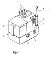
- the device comprises (fig.l) a base 1 in which is mounted a liquid pump, not shown, intended to send a liquid, for example water, contained in a removable tank 2, 'to a handpiece 3 connected to the pump by a conduit 4 and on which can be mounted interchangeable spray nozzles 5.
- the pump is actuated by a motor giving pulses at a frequency between 1000 to 4000 pulses per minute.
- the pump being driven by an asynchronous electric motor supplied by a 50 or 60 Hz network, its theoretical maximum frequency will be 3000 or 3600 pulses per minute, respectively. It is therefore reasonable in this case to locate the maximum frequency under load at 3000 pulses per minute.
- the operation of such an apparatus is described in particular in Swiss patent No 509 078.
- the device is provided with three spray nozzles 5 intended to project jets of pulsed liquid for oral hygiene, that is to say the washing of teeth and the massage of the gums.
- the head of these nozzles is designed so that the liquid flows in a heterogeneous jet so as to ensure an effective massage. Of the gums.
- Switching on of the device is controlled by a button 7 and a second button 6 adjusts the pressure.
- the apparatus further comprises another nozzle 8 called a nebulizing nozzle, the head of which differs from that of the nozzles 5 and is specially designed to spray the liquid in the form of a mist.
- a nebulizing nozzle the head of which differs from that of the nozzles 5 and is specially designed to spray the liquid in the form of a mist.
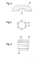
- This head is constituted, according to FIGS. 2 to 6, by an external envelope 9 delimiting an internal chamber 10 approximately cylindrical and which opens to the outside by a circular opening 11.
- a part 12 of this chamber 10 has a slightly larger diameter and delimits an internal shoulder 13 while the circular opening 11 is surrounded by a flange 14 directed inwards.
- the chamber 10 communicates with the supply conduit 4 coming from the pump via an internal conduit 15 which passes through the rod of the nozzle 8; an internal core 16, integral with the casing 9 protrudes inside this chamber and its function will be explained later.
- a cylindrical sleeve 17 which bears against the shoulder 13 and which is provided at its end directed towards the outside with a wall 18.
- the internal face of this wall 18 is provided with three grooves 19 arranged tangentially to the flared part of a conical central orifice 20 formed in the wall 18 and which opens on the external face of said wall, by a small cylindrical orifice 21
- the profile of the grooves is trapezoidal, as illustrated in FIG. 4.
- a cylindrical central axis 22 (fig. 5 and 6) which is blocked between the face d end 23 of the core 16 and the side wall 18 of the sleeve 17.
- This axis 22 is provided on its periphery with axial ribs 24, of approximately section semi-cylindrical, and which extend over most of its length leaving only a free space 25 on the side which is applied against the side wall 18 of the socket 17.
- the liquid coming from the reservoir 2 is sent by the pump into the conduit 15, it enters the liquid chamber 10, separates into several paths between the ribs 24 of the axis 22, then it reaches the wall 18 of the socket 17 and fills the small annular chamber 26 delimited by the end 25 of the axis and the wall 18, finally it flows with force in the three tangential grooves 19 formed in the wall 18, which cause it to take a vortex movement in the conical orifice 20 from which it exits in the form of mist through the small cylindrical orifice 21.
- the pressure of the liquid must be between 2.5 and 10 kg / cm 2 (peak value) or an average value between 1.5 and 3 kg / cm 2 .
- the three tangential grooves 19, the conical orifice 20 as well as the cylindrical outlet orifice 20 are dimensioned and arranged so as to obtain an optimum mist by the Vortrex effect.
- the water flow of the mist should be between 10 and 100 ml / minute because only a small amount of water gets inside the skin.
- This invention advantageously makes it possible to use this nozzle 8 for spraying different kinds of liquid on the face or if necessary another part of the body, for example solutions containing refreshing, toning, cleansing, flavoring moisturizing substances, etc.
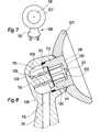
- FIGS. 7 and 8 is illustrated a second embodiment of a nebulizing nozzle 108 comprising, like the nozzle of FIG. 2, an envelope 109 inside which is formed a chamber 110 into which the supply conduit 115 opens.
- the circular opening of the envelope 109 is closed by a sleeve 117 pressing against an internal shoulder 113 delimited by a part 112 of the chamber 110 having a diameter greater than that of the interior part of the chamber.
- One end of the socket 117 is closed by a wall 118 which has the same structure as the wall 18 of the socket 17 in FIG. 2.
- a cylindrical axis 122 of the same structure as the axis 22 is supported on one side against the internal face of the wall 118 and the other against a core 116 of the chamber 110.
- the sleeve 117 is welded near the shoulder 113 to the envelope 109 by ultrasound.
- a tube 128 made of elastic material surrounding the core 116 and pressing on one side against the bottom of the chamber 110 and on the other against the cylindrical axis 122 ensures the axial positioning of this the latter in particular so that the external face of said axis 122 is in contact with the internal face of wall 118 and to prevent axis 122 moves under the effect of vibrations.
- a spring in place of the tube 128.
- the pressure to be exerted is relatively low and a tube of rubber or any other elastic material is sufficient and allows to have a symmetrical distribution of the pressure on the axis 122.
- a filter 129 is interposed between the axis 122 and the core 116 and it rests near its periphery on an internal shoulder 130 of the sleeve 117.
- the purpose of this filter is to prevent impurities block the orifice 121 of the nozzle or the grooves located inside the socket 117.
- a deflector 127 having the shape of a cup is rigidly fixed on the front part of the socket and is supported against the periphery of the opening of the envelope 109 of the nozzle 108.
- the shape of the deflector 127 makes it possible to avoid a great dispersion of the mist perpendicular to the axis of the orifice 121 which is thus directed towards the face under the shape of a cone whose axis is the axis of the orifice 121.
- the axis of the rod 131 and the head axis of the nozzle 108 are not perpendicular as is usually the case for the spray nozzles 5 and the nebulizing nozzle 8.
- the angular position of the rod 131 relative to the head of the nozzle facilitates this operation because thus the user can hold the handpiece in a more natural position ensuring that the mist is directed perpendicular to the skin.
- nebulizing nozzles could also be mounted on a tankless device, which would connect directly to a water source, for example a tap.
- a combined device the handpiece of which is designed to receive, as desired, a spray nozzle for the massage of the gums or a toothbrush, such as the device illustrated in FIG. 9.
- This device comprises a base 101 in which is mounted the pump for the liquid contained in the reservoir 102 supplying a handpiece 103 connected to the pump by a flexible hose 104.
- the device as illustrated comprises two toothbrushes 105a, a oral irrigation nozzle 105 and a nebulizing nozzle 108 mounted on the handpiece.
- the pump motor is controlled by the button 107 and the pump pressure is adjusted by the button 106.
- the handpiece 103 is provided with a hydraulic motor whose piston is mechanically connected with a carrying shaft -instruments to which can be attached by its rod, a toothbrush 105a or a spray nozzle 5 or a nebulizing nozzle 108.
- the brush 105a When the brush 105a is used the hydraulic motor is driven and oscillates the shaft with the brush tooth, if a nozzle is used the hydraulic motor does not work and it is the nozzle only which is supplied by the pump.
- Hydraulic motors for driving toothbrushes are known, a preferred type of these motors is described in French patent No 2,357,752 and US patent No 4,146,020.
- the piston of such an engine drives the shaft of the handpiece carrying the toothbrush in oscillating motion, itself being driven in oscillating motion under the action of a pulsed liquid. by the device pump and a return spring.
- the cylinder of the hydraulic motor is permanently connected to the outlet of the pump and in the case considered (above-mentioned patents) is a section of the water supply duct for the spray nozzle.
- a system made up of two distributors makes it possible to regulate the circulation of the liquid in three ways, 1 ° circulation in closed circuit that is to say to return to the upstream of the pump or in the container containing the liquid while the pump works and the handpiece is out of service, 2 0 to go out by the jet of nozzle for the massage of the gums, and 3 0 to actuate the piston without there being a flow of liquid only by the oscillating movement of a column of liquid, under the action of the pump.
- the piston of the hydraulic motor remains in principle stationary due to the low pressure pulses and the action of the return spring.
- Handpiece 103 is provided with such a hydraulic motor.
- the flexible hose 104 contains two conduits, one for the supply and the other for the return of the liquid.
- the distributor controlling the circulation in a closed circuit is controlled by a lever arranged outside the handpiece, the second is controlled directly by the shape of the foot for fixing the various accessories to the handpiece as will be described later. using Figures 10 to 12a.
- the piston of the hydraulic motor should not be driven.
- a spray nozzle 5 is mounted on the handpiece 103, efforts have so far been made to size the pump, the motor and the conduits so that the the spray nozzle remains stationary, the pressure pulses in the engine cylinder not being sufficient to overcome the force of the return spring.
- an angular oscillation of the nebulizing nozzle 108 with an amplitude between 10 o and 20, preferably 15 ° is beneficial because it ensures better distribution of the mist on the skin and increases the effect. massage.
- the oscillation frequency is preferably between 30 and 60 Hz.
- FIG 10 is shown the head of the handpiece 103 without cap.
- the lever controlling the distributor for circulating in a closed circuit of the liquid is illustrated in 133.
- the second distributor is controlled by a rod 134 secured to a sliding part 135 guided by a pin 136 and surrounding the hollow shaft 137 receiving the various accessories.
- the sliding part 135 illustrated in solid lines corresponds to the position of the dispenser allowing the liquid to pass through the hollow shaft for the supply of a nebulizing nozzle or a spray nozzle.
- the position indicated in dashed lines corresponds to the position where there is no liquid flow and the hydraulic motor drives the toothbrush.
- the sliding part 135 is brought back to the position indicated by dashed lines under the action of a spring not shown.
- a ring 138 integral with the shaft 137 allows the accessories to be fixed in the axial direction by snap-fastening, corresponding profiles being provided on the ring and the base of the rods of the instruments.
- the angular positioning of the accessories relative to the shaft is ensured by a shaft 137a rib in collaboration with a notch 139 and 140 (fig.11a, 12a) of the foot of the rods of the accessories.
- a notch 139 and 140 fig.11a, 12a
- the length of the two projections 108a is such that during the fixing of the rod 108 the sliding part 135 is pushed downwards thus actuating by the rod 134 the distributor opening to the liquid the circuit allowing it to arrive by the hollow shaft 137 to the nozzle 108.
- the stem base of a toothbrush 105a has the same configuration with the difference that the axial projections are shorter so that the sliding piece 135 is not pushed down and it remains at the position illustrated in dashed lines.
- the different characteristics of the motor and of the pump are adjusted so that the nebulizing nozzle is driven in angular oscillation of amplitude between 10 ° and 20 °, preferably 15 °, the amplitude for the toothbrush being greater than this value.
- the stem foot of this spray nozzle 5 has the same configuration as that of the nozzle 108, two axial projections 5a and one latching profile 142, but in addition the two projections 5a are extended by two tabs 5b to cooperate with a female profile 143 of the sliding part 135 and thus block the shaft 137 which would tend to oscillate.
- the invention is also applicable to known combined devices provided with an electric motor for driving an oscillating toothbrush movement; this engine can be according to the invention easily used for driving a nebulizing nozzle. In this case it is enough to adjust the characteristics of the motor to obtain the amplitude of the oscillation desired for the nebulizing nozzle, which is less than that of the brush, the frequency of oscillation can remain the same as for the brush.
Abstract
Description
La présente invention a pour objet un appareil pour soins corporels.The present invention relates to an apparatus for personal care.
On connaît des appareils spécialement conçus pour l'hygiène buccale pour assurer le nettoyage des dents et le massage des gencives par la projection d'un liquide, notamment du CH-A-604.678. Ces appareils comportent généralement un réservoir pour le liquide de nettoyage, une buse reliée au réservoir par un conduit d'alimentation et une pompe permettant de pomper le liquide du réservoir vers la buse. La buse est généralement montée amoviblement sur une pièce à main afin de permettre aux divers utilisateurs d'une même famille d'utiliser sa buse personnelle. La pièce à main est conçue de telle façon que la buse projette sur la gencive ou les dents un jet de liquide pulsé.Apparatuses specially designed for oral hygiene are known for cleaning teeth and massaging the gums by spraying a liquid, in particular CH-A-604.678. These devices generally include a reservoir for the cleaning liquid, a nozzle connected to the reservoir by a supply conduit and a pump making it possible to pump the liquid from the reservoir to the nozzle. The nozzle is generally removably mounted on a handpiece in order to allow various users of the same family to use their personal nozzle. The handpiece is designed in such a way that the nozzle projects a jet of pulsed liquid onto the gum or the teeth.
Certaines pièces à main sont également conçues pour que la buse de giclage puisse être remplacée par une brosse à dents laquelle se trouve être entraînée selon un mouvement oscillant par un moteur hydraulique monté dans la pièce à main, comme décrit dans les brevets allemand 1.802.838 et français 2.357.752. Ces appareils combinés permettent avantageusement d'assurer une hygiène complète de la bouche avec un minimum d'instruments, puisque sur la même pièce à main fonctionnant avec un appareil unique, les divers membres d'une même famille peuvent utiliser alternativement leur buse de giclage ou leur brosse à dent personnelle.Some handpieces are also designed so that the spray nozzle can be replaced by a toothbrush which happens to be driven in an oscillating movement by a hydraulic motor mounted in the handpiece, as described in German patents 1,802,838 and French 2,357,752. These devices advantageously make it possible to ensure complete hygiene of the mouth with a minimum of instruments, since on the same handpiece operating with a single device, the various members of the same family can alternately use their spray nozzle or their brush with personal tooth.
Ces appareils sont donc uniquement conçus pour l'hygiène buccale. Ces dernières années on a introduit sur le marché d'autres types d'appareils destinés aux soins de la peau du visage et spécialement pour le nettoyage et l'hydratation de la peau. En effet des recherches médicales ont montré que le visage humain perd environ 40 millilitres d'eau par jour. Pour réhydrater la peau il faut lui appliquer un brouillard d'eau ou autre liquide. Une hydratation efficace dépend principalement de l'humidité relative de la peau, de la température du visage et de la différence de pression entre la peau et le liquide projeté. Il faut notamment une pression minimale de 21 millimètres de mercure pour que l'eau pénètre dans la peau. Dans ce but on a développé des appareils nébulisateurs munis d'une buse spéciale dont la géométrie permet de créer un tourbillon qui entraîne une projection de liquide sous forme de brouillard et non de gouttelettes. Ces appareils permettent d'hydrater la peau, et également de la tonifier ou encore de la nettoyer en profondeur. Ces appareils sont donc spécialement conçus pour leur fonction particulière et actuellement on en connaît deux types principaux sur le marché. Le premier type est constitué par des récipients aérosols qui travaillent avec un agent pressurisé, notamment du gaz liquéfié, qui a une pression interne suffisamment élevée pour donner, avec une buse de giclage appropriée, un brouillard. Ce genre d'appareil est sans problème si ce n'est que l'utilisateur est limité au seul produit qui est emmagasiné dans le récipient, donc à un seul arôme et une seule composition, à moins de posséder plusieurs recipients aérosols ce qui risque d'être encombrant, et en outre, après plusieurs utilisations, la pression à l'intérieur du récipient tend à diminuer et le brouillard tend à se transformer en gouttelettes de liquide, ce qui ne donne plus l'effet recherché. Par ailleurs, ce type d'appareil n'est pas très économique puisque les récipients ne sont pas rechargeables et doivent être simplement jetés dès qu'ils sont vides, ce qui constitue un gaspillage inutile.These devices are therefore only designed for oral hygiene. In recent years, other types of devices have been introduced into the market for facial skin care, especially for cleansing and moisturizing the skin. Indeed, medical research has shown that the human face loses approximately 40 milliliters of water per day. To rehydrate the skin, apply a mist of water or other liquid to it. Effective hydration depends mainly on the relative humidity of the skin, the temperature of the face and the pressure difference between the skin and the projected liquid. In particular, a minimum pressure of 21 millimeters of mercury is required for water to enter the skin. For this purpose we have developed nebulizers with a special nozzle whose geometry allows to create a vortex which causes a projection of liquid in the form of mist and not of droplets. These devices moisturize the skin, and also tone it or even clean it thoroughly. These devices are therefore specially designed for their particular function and currently two main types are known on the market. The first type consists of aerosol containers which work with a pressurized agent, in particular liquefied gas, which has an internal pressure high enough to give, with an appropriate spray nozzle, a mist. This kind of device is without problem except that the user is limited to the only product which is stored in the container, therefore to a single flavor and a single compound. tion, unless you have several aerosol containers which may be bulky, and in addition, after several uses, the pressure inside the container tends to decrease and the mist tends to turn into droplets of liquid, which no longer gives the desired effect. Furthermore, this type of device is not very economical since the containers are not refillable and must be simply thrown away as soon as they are empty, which constitutes unnecessary waste.
Un deuxième type de nébulisateur connu est particulièrement conçu pour le nettoyage de la peau et à cet effet il envoie un nuage de vapeur d'eau grâce à un moyen de chauffage par résistance. Ce genre d'appareil est avant tout utilisé dans les instituts de beauté pour nettoyer la peau èn profondeur et est dans ce domaine d'une grande efficacité. On connaît depuis peu des appareils de ce type utilisables à domicile, projetant sur le visage une fine brume d'eau grâce à un moyen de chauffage. Cependant, tant que ce type d'appareil était utilisé dans les instituts de beauté par une esthéticienne compétente, il n'était pas dangereux, l'esthéticienne veillant à ce que le jet de liquide vaporisé soit placé à bonne distance du visage, il n'en est pas de même quand une utilisatrice fait elle-même ce genre de soins à domicile, sans surveillance, elle risque d'approcher l'appareil trop près de sa peau et de subir par conséquent des brûlures.A second known type of nebulizer is particularly designed for cleaning the skin and for this purpose it sends a cloud of water vapor by means of resistance heating. This type of device is primarily used in beauty salons to thoroughly cleanse the skin and is very effective in this area. Recently, devices of this type have been known for use at home, projecting a fine mist of water onto the face by means of heating. However, as long as this type of device was used in beauty salons by a competent esthetician, it was not dangerous, the esthetician ensuring that the spray of liquid spray was placed at a good distance from the face, it n It is not the same when a user does this kind of care at home herself, without supervision, she risks approaching the device too close to her skin and consequently suffering burns.
En résumé, les personnes soucieuses de ménager ou d'embellir leurs dents, leurs gencives, leur visage, leur corps, doivent posséder dans leur salle de bain d'une part un appareil spécialement conçu pour les soins buccaux, d'autre part un autre appareil spécialement conçu pour les soins de la peau ou un ou plusieurs récipients aérosols appropriés contenant divers liquides de traitement. Le fait de devoir se munir de nombreux appareils pour arriver à une hygiène complète et efficace est un obstacle au développement de ces soins, d'une part pour des raisons d'économie, d'autre part pour des raisons d'encombrement.In summary, people who want to preserve or beautify their teeth, gums, face, body, must have in their bathroom on the one hand a device specially designed for oral care, on the other hand device specially designed for skin care or one or more suitable aerosol containers containing various li treatment. The fact of having to bring many devices to achieve complete and effective hygiene is an obstacle to the development of this care, on the one hand for reasons of economy, on the other hand for reasons of space.
La présente invention se propose de pallier ces inconvénients.The present invention proposes to overcome these drawbacks.
A cet effet l'invention concerne un appareil pour soins corporels comprenant une pièce à main reliée par un conduit à une source de liquide, une pompe connectée au conduit de liquide pour projeter ledit liquide en jets hétérogènes à une fréquence comprise entre 1000 et 4000 impulsions par minute, des buses de giclage interchangeables destinées à être montées sur la pièce à main pour le traitement des dents et des gencives, caractérisé par le fait que l'appareil est équipé en outre d'une buse nébulisatrice adaptée à être également montée sur la pièce à main en vue de produire un brouillard pour les soins de la peau.To this end, the invention relates to an apparatus for personal care comprising a handpiece connected by a conduit to a source of liquid, a pump connected to the liquid conduit for projecting said liquid in heterogeneous jets at a frequency between 1000 and 4000 pulses. per minute, interchangeable spray nozzles intended to be mounted on the handpiece for the treatment of teeth and gums, characterized in that the apparatus is further equipped with a nebulizing nozzle adapted to be also mounted on the handpiece for producing a skin care mist.
On obtient ainsi pour la première fois un appareil unique qui peut avantageusement servir à la fois pour l'hygiène de la bouche et pour les soins du visage qui évite les gaspillages, est économique, peu encombrant, et permet de régler la pression du liquide à la sortie de la buse. Enfin, dans le cas d'un appareil travaillant avec un réservoir, divers produits peuvent être additionnés à l'eau du réservoir pour hydrater, tonifier, rafraîchir, parfumer l'épiderme et il serait également possible de chauffer cette eau dans le cas où l'on voudrait obtenir un nettoyage en prodonfeur de la peau.A unique device is thus obtained for the first time which can advantageously be used both for mouth hygiene and for facial care which avoids waste, is economical, takes up little space and makes it possible to adjust the pressure of the liquid to be the nozzle outlet. Finally, in the case of an apparatus working with a reservoir, various products can be added to the water of the reservoir to hydrate, tone, refresh, perfume the epidermis and it would also be possible to heat this water in the case where the '' we would like to obtain a deep cleaning of the skin.
Etant donné que les appareils pour l'hygiène buccale connus travaillent avec une pompe qui donne des impulsions de liquide, il n'était pas évident que la même pompe pouvait être utilisée pour former un brouillard quasiment continu. Des essais ont permis de constater que ce brouillard arrivait par vagues successives qui donnaient l'effet d'un brouillard continu, mais qui amélioraient en outre les bienfaits du traitement.Since the known oral hygiene devices work with a pump which gives impulses sions of liquid, it was not obvious that the same pump could be used to form an almost continuous mist. Tests have shown that this mist came in successive waves which gave the effect of a continuous mist, but which also improved the benefits of the treatment.
Par ailleurs, l'utilisateur tient la même pièce à main, que ce soit pour les soins buccaux ou pour ceux du visage, en changeant simplement la buse. Cette pièce à main est beaucoup plus pratique qu'un appareil nébulisateur habituel, car elle est plus légère et plus maniable.In addition, the user holds the same handpiece, whether for oral or facial care, by simply changing the nozzle. This handpiece is much more practical than a conventional nebulizer, because it is lighter and more manageable.
Selon une forme préférée d'exécution la buse nébulisatrice est attachée sur un axe qui peut être entraîné en oscillation, par des moyèns d'entraînement logés dans la pièce à main, de préférence à une amplitude de 10° à 20° et à une fréquence de 30 à 60 Hz. En effet, il a été prouvé qu'une telle oscillation de la buse nébulisatrice est bénéfique car elle permet une meilleure répartition du brouillard projectée sur la peau et augmente l'effet de massage. Cette idée surprenante d'une oscillation d'une buse n'a jamais été envisagée d'autant moins que la buse d'irrigation pour l'hygiène buccale doit bien sûr rester fixe pour ne pas gêner l'utilisateur. Dans le cas d'un appareil combiné utilisable soit avec une brosse à dents soit une buse, muni d'un arbre creux porte-instruments sur lequel s'attache une brosse ou une buse, et comprenant un moteur hydraulique ou électrique assurant l'entraînement en mouvement oscillant de cet arbre si la brosse est utilisée, il suffit, lors de l'utilisation d'une buse nébulisatrice, de mettre en marche et régler certaines caractéristiques du moteur pour obtenir l'amplitude voulue qui est plus petite que pour le brossage. Il est également possible d'assurer l'entraînement en mouvement oscillant par une turbine hydraulique ou un résonateur hydraulique entraîné par exemple par l'eau courante d'un robinet et auquel on a associé un convertisseur de mouvement adéquat, les deux moyens d'entraînement susmentionnés étant connus dans le domaine de l'hygiène buccale.According to a preferred embodiment, the nebulizing nozzle is attached to an axis which can be driven in oscillation, by drive means housed in the handpiece, preferably at an amplitude of 10 ° to 20 ° and at a frequency from 30 to 60 Hz. Indeed, it has been proven that such an oscillation of the nebulizing nozzle is beneficial because it allows a better distribution of the mist projected on the skin and increases the massage effect. This surprising idea of an oscillation of a nozzle has never been envisaged, especially since the irrigation nozzle for oral hygiene must of course remain fixed so as not to disturb the user. In the case of a combined device usable either with a toothbrush or a nozzle, provided with a hollow shaft carrying instruments to which a brush or a nozzle is attached, and comprising a hydraulic or electric motor ensuring the drive in oscillating movement of this shaft if the brush is used, it suffices, when using a nebulizing nozzle, to start and adjust certain characteristics of the engine to obtain the desired amplitude which is smaller than for brushing . It is also possible to provide training in oscil movement lant by a hydraulic turbine or a hydraulic resonator driven for example by running water from a tap and with which an adequate movement converter has been associated, the two aforementioned drive means being known in the field of oral hygiene.
L'invention va être décrite ci-après à l'aide de la description qui suit des exemples d'exécution et en relation avec les dessins annexés dans lesquels :
- la figure 1 est une vue en perspective de l'appareil complet.
- La figure 2 est une vue de profil en coupe, et agrandie de la tête de la buse nébulisatrice destinée aux soins du visage.
- La figure 3 est une vue de la face interne de la douille interne selon la flèche III de la figure 2.
- La figure 4 est une vue en coupe de la paroi interne de la douille selon l'axe IV-IV'de la figure 3.,
- La figure 5 est une vue de profil de l'axe nébulisateur destiné à être monté dans la douille.
- La figure 6 est une vue en plan de l'axe de la figure 5.
- La figure 7 est une vue en perspective d'une seconde forme de buse nébulisatrice.
- La figure 8 est une vue de profil en coupe et agrandie de la tête de la figure précédente.
- La figure 9 est une vue en perspective d'une seconde forme d'appareil complet.
- La figure 10 est une vue de profil de la tête de la pièce à main.
- La figure 11 est une vue de profil du pied de fixation de la buse nébulisatrice.
- La figure lia est une vue de dessous de la figure 11.
- Les figures 12 et 12a sont des vues analogues aux figures 11 et 11a pour une buse de giclage pour le massage des gencives.
- Figure 1 is a perspective view of the complete apparatus.
- Figure 2 is a sectional side view, and enlarged of the head of the nebulizer nozzle for facial care.
- FIG. 3 is a view of the internal face of the internal sleeve according to arrow III of FIG. 2.
- FIG. 4 is a sectional view of the internal wall of the sleeve along the axis IV-IV ′ of FIG. 3.,
- Figure 5 is a side view of the nebulizer axis intended to be mounted in the socket.
- FIG. 6 is a plan view of the axis of FIG. 5.
- Figure 7 is a perspective view of a second form of nebulizing nozzle.
- Figure 8 is a sectional and enlarged profile view of the head of the previous figure.
- Figure 9 is a perspective view of a second form of complete apparatus.
- Figure 10 is a side view of the head of the handpiece.
- Figure 11 is a side view of the fixing foot of the nebulizer nozzle.
- Figure 11a is a bottom view of Figure 11.
- Figures 12 and 12a are views similar to Figures 11 and 11a for a spray nozzle for massaging the gums.
L'appareil comprend (fig.l) un socle 1 dans lequel est montée une pompe à liquide, non représentée, destinée à envoyer un liquide, par exemple de l'eau, contenu dans un réservoir amovible 2,'à une pièce à main 3 connectée à la pompe par un conduit 4 et sur laquelle peuvent être montées des buses de giclage 5 interchangeables. La pompe est actionnée par un moteur donnant des impulsions à une fréquence située entre 1000 à 4000 impulsions par minute. La pompe étant entraînée par un moteur électrique asynchrone alimenté par un réseau de 50 ou 60 Hz sa fréquence maximale théorique sera respectivement de 3000 ou 3600 impulsions par minute. On peut donc raisonnablement dans ce cas situer la fréquence maximale en charge à 3000 impulsions par minute. Le fonctionnement d'un tel appareil est notamment décrit dans le brevet suisse No.509 078.The device comprises (fig.l) a
Dans l'exemple considéré, l'appareil est muni de trois buses de giclage 5 destinées à projeter des jets de liquide pulsé pour l'hygiène buccale, c'est-à-dire le lavage des dents et le massage des gencives. La tête de ces buses est conçue pour que le liquide s'écoule en un jet hétérogène de manière à assurer un massage.efficace des gencives. La mise en marche de l'appareil est commandée par un bouton 7 et un deuxième bouton 6 permet de régler la pression.In the example considered, the device is provided with three
L'appareil comprend en outre une autre buse 8 appelée buse nébulisatrice dont la tête diffère de celle des buses 5 et est spécialement conçue pour projeter le liquide sous forme de brouillard.The apparatus further comprises another
Cette tête est constituée, selon les figures 2 à 6, par une enveloppe extérieure 9 délimitant une chambre interne 10 approximativement cylindrique et qui débouche à l'extérieur par une ouverture circulaire 11. Une partie 12 de cette chambre 10 a un diamètre légèrement supérieur et délimite un épaulement interne 13 tandis que l'ouverture circulaire 11 est entourée par un rebord 14 dirigé vers l'intérieur. La chambre 10 communique avec le conduit d'alimentation 4 provenant de la pompe via un conduit interne 15 qui traverse la tige de la buse 8 ; un noyau interne 16, solidaire de l'enveloppe 9 fait saillie à l'intérieur de cette chambre et sa fonction sera expliquée ultérieurement.This head is constituted, according to FIGS. 2 to 6, by an
Dans la partie 12 de plus grand diamètre est montée à force une douille cylindrique 17 qui s'appuie contre l'épaulement 13 et qui est munie à son extrémité dirigée vers l'extérieur d'une paroi 18. Sur la figure 3, on peut voir que la face interne de cette paroi 18 est munie de trois rainures 19 disposées tangentiellement à la partie évasée d'un orifice central conique 20 formé dans la paroi 18 et qui débouche sur la face externe de ladite paroi, par un petit orifice cylindrique 21. Le profil des rainures est trapézoidal, comme illustré figure 4. A l'intérieur de la douille 17 a été monté, préalablement à son assemblage, un axe central cylindrique 22 (fig.5 et 6) qui se trouve bloqué entre la face d'extrémité 23 du noyau 16 et la paroi latérale 18 de la douille 17. Cet axe 22 est muni sur sa périphérie de nervures axiales 24, à section approximativement demi-cylindrique, et qui s'étendent .sur la plus grande partie de sa longueur laissant seulement un espace libre 25 du côté qui s'applique contre la paroi latérale 18 de la douille 17. Une fois que la douille 17 et l'axe 22 ont été montés dans l'enveloppe 9, ils sont retenus dans cette enveloppe par une bague 27 qui s'appuie contre son rebord 14.In the
Quand la buse 8 est mise en place sur la pièce à main 3 pour effectuer un soin du visage, le liquide provenant du réservoir 2 est envoyé par la pompe dans le conduit 15, il entre dans la chambre de liquide 10, se sépare en plusieurs chemins entre les nervures 24 de l'axe 22, puis il atteint la paroi 18 de la douille 17 et remplit la petite chambre annulaire 26 délimitée par l'extrémité 25 de l'axe et la paroi 18, enfin il s'écoule avec force dans les trois rainures tangentielles 19 formées dans la paroi 18, lesquelles lui font prendre un mouvement tourbillonnaire dans l'orifice conique 20 d'où il sort sous forme de brouillard par le petit orifice cylindrique 21.When the
Afin que l'effet de nébulisation soit atteint et que l'eau pénètre dans la peau, la pression du liquide doit se situer entre 2,5 et 10 kg/cm2 (valeur de crête) ou en valeur moyenne entre 1,5 et 3 kg/cm2. Les trois rainures tangentielles 19, l'orifice conique 20 ainsi que l'orifice cylindrique de sortie 20 sont dimensionnés et disposés de manière à obtenir un brouillard optimum par l'effet Vortrex. Le débit d'eau du brouillard doit être compris entre 10 et 100 ml/minute car seulement une faible quantité d'eau pénètre à l'intérieur de la peau.In order for the nebulization effect to be achieved and water to penetrate the skin, the pressure of the liquid must be between 2.5 and 10 kg / cm 2 (peak value) or an average value between 1.5 and 3 kg / cm 2 . The three
Cette invention permet avantageusement d'utiliser cette buse 8 pour pulvériser différentes sortes de liquide sur le visage ou le cas échéant une autre partie du corps, par exemple des solutions contenant des substances hydratantes rafraîchissantes, tonifiantes, nettoyantes, arômatisantes, etc.This invention advantageously makes it possible to use this
Il est également possible de prévoir un chauffage de l'eau à l'intérieur du récipient 2 afin que le brouillard d'eau à la sortie de la buse nébulisatrice soit lui-même chaud, ce qui pourrait améliorer l'action de la nébulisation dans le cas d'un nettoyage de la peau. Cependant il a été prouvé médicalement que l'eau doit être à une température d'environ 27°C pour un effet optimum sans risque pour la peau.It is also possible to provide a heating of the water inside the
A la figure 7 et 8 est illustrée une deuxième exécution d'une buse nébulatrice 108 comprenant, comme la buse de la figure 2, une enveloppe 109 à l'intérieur de laquelle est formée une chambre 110 dans laquelle débouche le conduit d'alimentation 115. L'ouverture circulaire de l'enveloppe 109 est fermée par une douille 117 s'appuyant contre un épaulement interne 113 délimité par une partie 112 de la chambre 110 présentant un diamètre supérieur à celui de la partie intérieure de la chambre. Une des extrémités de la douille 117 est fermée par une paroi 118 qui présente la même structure que la paroi 18 de la douille 17 de la figure 2. Un axe cylindrique 122 de même structure que l'axe 22 s'appuie d'un côté contre la face interne de la paroi 118 et de l'autre contre un noyau 116 de la chambre 110. La douille 117 est soudée à proximité de l'épaulement 113 à l'enveloppe 109 par ultrasons. Pendant l'opération du soudage par ultrasons un tube 128 en matériau élastique entourant le noyau 116 et s'appuyant d'un côté contre le fond de la chambre 110 et de l'autre contre l'axe cylindrique 122 assure le positionnement axial de ce dernier notamment pour que la face extérieure dudit axe 122 soit en contact avec la face interne de la paroi 118 et pour éviter que l'axe 122 se déplace sous l'effet des vibrations. Bien sûr il est possible d'utiliser un ressort à la place du tube 128. Néanmoins, la pression qu'il faut exercer est relativement faible et un tube en caoutchouc ou tout autre matériau élastique suffit et permet d'avoir une répartition symétrique de la pression sur l'axe 122. Un filtre 129 est interposé entre l'axe 122 et le noyau 116 et il s'appuie près de son pourtour sur un épaulement interne 130 de la douille 117. Le but de ce filtre est d'empêcher que des impuretés viennent boucher l'orifice 121 de la buse ou les rainures situées à l'intérieur de la douille 117. Enfin, un déflecteur 127 ayant la forme d'une coupelle est fixée rigidement sur la partie antérieure de la douille et s'appuie contre le pourtour de l'ouverture de l'enveloppe 109 de la buse 108. La forme du déflecteur 127 permet d'éviter une grande dispersion du'brouillard perpendiculairement à l'axe de l'orifice 121 qui est ainsi dirigé vers le visage sous la forme d'un cône dont l'axe est l'axe de l'orifice 121.In FIGS. 7 and 8 is illustrated a second embodiment of a
L'axe de la tige 131 et l'axe de tête de la buse 108 (déterminant l'axe de la projection) ne sont pas perpendiculaires comme c'est le cas habituellement pour les buses de giclage 5 et la buse nébulisatrice 8. En effet pour que le brouillard conserve toute la puissance de pénétration dans la peau il faut qu'il soit dirigé perpendiculairement à la surface à traiter il faut donc que la tige et partant la pièce à main soit tenue parallèlement au visage, ce qui n'est pas aisé. La position angulaire de la tige 131 par rapport à la tête de la buse facilite cette opération car ainsi l'utilisateur peut tenir la pièce à main dans une position plus naturelle assurant que le brouillard est dirigé perpendiculairement à la peau.The axis of the
Par ailleurs, de telles buses nébulisatrices pourraient également être montées sur un appareil sans réservoir, qui se brancherait directement sur une source d'eau, par exemple un robinet. Une autre possibilité est d'utiliser ces buses avec un appareil combiné dont la pièce à main est prévue pour recevoir au choix une buse de giclage pour le massage des gencives ou une brosse à dents, tel que l'appareil illustré à la figure 9. Cet appareil comprend un socle 101 dans lequel est montée la pompe de liquide contenu dans le réservoir 102 alimentant une pièce à main 103 connectée à la pompe par un tuyau flexible 104. L'appareil tel qu'illustré comprend deux brosses à dents 105a, une buse d'irrigation buccale 105 et une buse nébulisatrice 108 montée sur la pièce à main. Il est évident que le nombre de ces accessoires peut varier selon le nombre de membres de la famille, l'illustration de la figure 9 n'est qu'un exemple parmi les différentes combinaisons. Le moteur de la pompe est commandé par le bouton 107 et la pression de la pompe est réglée par le bouton 106. Dans ce cas, la pièce à main 103 est munie d'un moteur hydraulique dont le piston est connecté mécaniquement avec un arbre porte-instruments sur lequel peut être attachée par sa tige, une ` brosse à dent 105a ou une buse de giclage 5 ou une buse nébulatrice 108. Quand la brosse 105a est utilisée le moteur hydraulique est entraîné et fait osciller l'arbre avec la brosse à dent, si une buse est utilisée le moteur hydraulique ne fonctionne pas et c'est la buse seule qui est alimentée par la pompe.Furthermore, such nebulizing nozzles could also be mounted on a tankless device, which would connect directly to a water source, for example a tap. Another possibility is to use these nozzles with a combined device, the handpiece of which is designed to receive, as desired, a spray nozzle for the massage of the gums or a toothbrush, such as the device illustrated in FIG. 9. This device comprises a base 101 in which is mounted the pump for the liquid contained in the
Les moteurs hydrauliques pour l'entraînement des brosses à dents sont connus, un type préféré de ces moteurs est décrit dans le brevet français No.2.357.752 et le brevet US No.4.146.020. Le piston d'un tel moteur entraîne en mouvement oscillant l'arbre de la pièce à main portant la brosse à dents, lui-même étant entraîné en mouvement oscillant sous l'action d'un liquide pulsé par la pompe de l'appareil et un ressort de rappel. Le cylindre du moteur hydraulique est relié de façon permanente avec la sortie de la pompe et dans le cas considéré (brevets susmentionnés) est une section du conduit d'alimentation en eau pour la buse de giclage. Un système composé de deux distributeurs permet de régler la circulation du liquide de trois façons, 1° circulation en circuit fermé c'est-à-dire de revenir à l'amont de la pompe ou dans le récipient contenant le liquide pendant que la pompe fonctionne et la pièce à main est hors service, 20 de sortir par la buse de giclage pour le massage des gencives, et 30 d'actionner le piston sans qu'il y ait un débit de liquide uniquement par le mouvement oscillant d'une colonne de liquide, sous l'action de la pompe. Pendant la circulation en circuit fermé ou par la buse de giclage du liquide le piston du moteur hydraulique reste en principe immobile à cause des faibles impulsions de pression et l'action du ressort de rappel.Hydraulic motors for driving toothbrushes are known, a preferred type of these motors is described in French patent No 2,357,752 and US patent No 4,146,020. The piston of such an engine drives the shaft of the handpiece carrying the toothbrush in oscillating motion, itself being driven in oscillating motion under the action of a pulsed liquid. by the device pump and a return spring. The cylinder of the hydraulic motor is permanently connected to the outlet of the pump and in the case considered (above-mentioned patents) is a section of the water supply duct for the spray nozzle. A system made up of two distributors makes it possible to regulate the circulation of the liquid in three ways, 1 ° circulation in closed circuit that is to say to return to the upstream of the pump or in the container containing the liquid while the pump works and the handpiece is out of service, 2 0 to go out by the jet of nozzle for the massage of the gums, and 3 0 to actuate the piston without there being a flow of liquid only by the oscillating movement of a column of liquid, under the action of the pump. During circulation in a closed circuit or through the liquid spray nozzle, the piston of the hydraulic motor remains in principle stationary due to the low pressure pulses and the action of the return spring.
La pièce à main 103 est munie d'un tel moteur hydraulique. Le tuyau flexible 104 contient deux conduits un pour l'alimentation et l'autre pour le retour du liquide. Le distributeur commandant la circulation en circuit fermé est commandée par un levier disposé à l'extérieur de la pièce à main, la seconde est commandée directement par la forme du pied de fixation des différents accessoires sur la pièce à main comme il sera décrit plu loin à l'aide des figures 10 à 12a.
Comme mentionné précédemment pendant que la pièce à main 103 est utilisée pour le giclage des gencives le piston du moteur hydraulique ne devrait pas être entraîné. Afin d'éviter ces oscillations indésirables, lorsqu'une buse de giclage 5 est montée sur la pièce à main 103, on a jusqu'à maintenant cherché à dimensionner la pompe le moteur et les conduits de sorte que la buse de giclage reste immobile les impulsions de pression dans le cylindre du moteur n'étant pas suffisantes pour vaincre la force du ressort de rappel. Il a été trouvé que contrairement au giclage des gencives une oscillation angulaire de la buse nébulisatrice 108 d'une amplitude comprise entre 10o et 20 de préférence 15° est bénéfique car elle assure une meilleure répartition du brouillard sur la peau et augmente l'effet de massage. La fréquence d'oscillation est comprise de préférence entre 30 et 60 Hz. Il est possible de chercher à dimensionner la pompe et le moteur de sorte que la buse nébulisatrice 108 soit entraînée en mouvement oscillant lorsqu'elle est montée sur la pièce à main et que la buse de giclage 5 reste immobile en tenant compte par exemple de la différence de section entre l'orifice 121 d'une buse nébulisatrice et celle d'une buse de giclage. Afin d'éliminer l'oscillation qui est gênante lors de l'utilisation d'une buse de giclage avec une pièce à main contenant un moteur hydraulique, on a réalisé un système de fixation représenté aux figures 12 et 12a bloquant mécaniquement l'arbre 137 du moteur.As previously mentioned while
A la figure 10 est représentée la tête de la pièce à main 103 sans capuchon. Le levier commandant le distributeur de mise en circulation en circuit fermé du liquide est illustrée en 133. Le second distributeur est commandé par une tige 134 solidaire d'une pièce coulissante 135 guidée par une cheville 136 et entourant l'arbre creux 137 recevant les différents accessoires. La pièce coulissante 135 illustrée en traits pleins correspond à la position du distributeur laissant passer le liquide à travers l'arbre creux pour l'alimentation d'une buse nébulatrice ou une buse de giclage. La position indiquée en traits mixtes correspond à la position où il n'y a pas de débit de liquide et le moteur hydraulique entraîne la brosse à dent. La pièce coulissante 135 est ramenée à la position indiquée en traits mixtes sous l'action d'un ressort non représenté. Une bague 138 solidaire de l'arbre 137 permet la fixation dans le sens axial des accessoires par encliquetage, des profils correspondants étant prévus sur la bague et le pied des tiges des instruments. Le positionnement angulaire des accessoires par rapport à l'arbre est assuré par une nervure 137a de arbre en collaboration avec une échancrure 139 et 140 (fig.11a, 12a) du pied des tiges des accessoires. Lors de la fixation de la tige 108 d'une buse nébulisatrice deux projections axiales 108a du pied de la tige 108 munies d'un profil d'encliquetage 141 assurent le positionnement axial de la buse. L'échancrure 139 collaborant avec la nervure 137a assure le positionnement angulaire. La longueur des deux projections 108a est telle que lors de la fixation de la tige 108 la pièce coulissante 135 soit poussée vers le bas actionnant ainsi par la tige 134 le distributeur ouvrant au liquide le circuit lui permettant d'arriver par l'arbre creux 137 à la buse 108. Le pied de tige d'une brosse à dent 105a présente la même configuration à la différence que les projections axiales sont plus courtes de sorte que la pièce coulissante 135 n'est pas poussée vers le bas et elle reste à la position illustrée en traits mixtes.In Figure 10 is shown the head of the
On règle les différentes caractéristiques du moteur et de la pompe de sorte que la buse nébulisatrice soit entraînée en oscillation angulaire d'amplitude entre 10° et 20° de préférence 15°, l'amplitude pour la brosse à dents étant supérieure à cette valeur.The different characteristics of the motor and of the pump are adjusted so that the nebulizing nozzle is driven in angular oscillation of amplitude between 10 ° and 20 °, preferably 15 °, the amplitude for the toothbrush being greater than this value.
Pour éviter justement cette oscillation angulaire, dans le cas d'une buse d'irrigation buccale, le pied de tige de cette buse de giclage 5 a la même configuration que celui de la buse 108, deux projections axiales 5a et un profil d'encliquetage 142, mais en plus les deux projections 5a se prolongent par deux languettes 5b pour coopérer avec un profil femelle 143 de la pièce coulissante 135 et bloquer ainsi l'arbre 137 qui aurait tendance à osciller.To avoid precisely this angular oscillation, in the case of an oral irrigation nozzle, the stem foot of this
Ainsi il n'est plus utile de recourir à un dimensionnement délicat de la pompe et du moteur pour obtenir que- d'un côté la buse de giclage reste immobile et de l'autre-côté la buse nébulisatrice soit entraînée.Thus, it is no longer useful to resort to delicate sizing of the pump and of the motor in order to obtain that on one side the spray nozzle remains stationary and on the other side the nebulizing nozzle is driven.
L'invention est aussi applicable aux appareils combinés connus munis d'un moteur électrique pour l'entraînement en mouvement oscillant d'une brosse à dents ; ce moteur peut être selon l'invention facilement utilisé pour l'entraînement d'une buse nébulisatrice. Dans ce cas il suffit de régler les caractéristiques du moteur pour obtenir l'amplitude de l'oscillation voulue pour la buse nébulisatrice, qui est inférieure à celle de la brosse, la fréquence d'oscillation peut rester la même que pour la brosse.The invention is also applicable to known combined devices provided with an electric motor for driving an oscillating toothbrush movement; this engine can be according to the invention easily used for driving a nebulizing nozzle. In this case it is enough to adjust the characteristics of the motor to obtain the amplitude of the oscillation desired for the nebulizing nozzle, which is less than that of the brush, the frequency of oscillation can remain the same as for the brush.
De même on peut utiliser une turbine hydraulique ou un résonateur hydraulique entraîné par exemple par la pression de l'eau du robinet en associant un convertisseur de mouvement pour la transformation du mouvement de rotation de la turbine respectivement du résonateur en mouvement oscillant angulaire.Similarly, it is possible to use a hydraulic turbine or a hydraulic resonator driven for example by the pressure of tap water by associating a motion converter for transforming the rotational movement of the turbine respectively of the resonator into angular oscillating motion.
Claims (10)
Applications Claiming Priority (2)
| Application Number | Priority Date | Filing Date | Title |
|---|---|---|---|
| US26948881A | 1981-06-02 | 1981-06-02 | |
| US269488 | 1981-06-02 |
Publications (3)
| Publication Number | Publication Date |
|---|---|
| EP0066930A2 true EP0066930A2 (en) | 1982-12-15 |
| EP0066930A3 EP0066930A3 (en) | 1983-07-20 |
| EP0066930B1 EP0066930B1 (en) | 1986-03-12 |
Family
ID=23027466
Family Applications (1)
| Application Number | Title | Priority Date | Filing Date |
|---|---|---|---|
| EP82200674A Expired EP0066930B1 (en) | 1981-06-02 | 1982-06-02 | Device for body care |
Country Status (2)
| Country | Link |
|---|---|
| EP (1) | EP0066930B1 (en) |
| DE (1) | DE3269793D1 (en) |
Cited By (4)
| Publication number | Priority date | Publication date | Assignee | Title |
|---|---|---|---|---|
| EP0298910A1 (en) * | 1987-06-22 | 1989-01-11 | Les Produits Associes L.P.A. Broxo S.A. | Apparatus and method for the care of the mouth and throat |
| EP0550943A1 (en) * | 1990-04-05 | 1993-07-14 | Samuel Jackson Martz | Apparatus for the treatment of patients with papulosquamous disorders |
| WO2004034923A1 (en) * | 2002-10-17 | 2004-04-29 | Braun Gmbh | Mouth rinse and spray nozzle for creating a liquid jet and teeth-cleaning system |
| CN113274158A (en) * | 2021-05-11 | 2021-08-20 | 王丹 | Novel oral care instrument and care method thereof |
Citations (6)
| Publication number | Priority date | Publication date | Assignee | Title |
|---|---|---|---|---|
| CH468806A (en) * | 1968-01-12 | 1969-02-28 | Sophindar Ets | Body care equipment |
| FR2122972A5 (en) * | 1971-01-19 | 1972-09-01 | Woog Inst Rech | |
| US3739983A (en) * | 1970-01-22 | 1973-06-19 | Woog Inst Rech | Multi-jet spray nozzle with a movable shutter member |
| US3861383A (en) * | 1973-09-24 | 1975-01-21 | Leslie J Kovach | Skin massaging instrument |
| US3871560A (en) * | 1973-08-01 | 1975-03-18 | Prod Associes Sa | Reservoir for a liquid pump including means for initially forcing liquid into the pump |
| US3910266A (en) * | 1973-08-15 | 1975-10-07 | Ricoh Watch | Method and apparatus for beauty and therapeutic treatment |
-
1982
- 1982-06-02 DE DE8282200674T patent/DE3269793D1/en not_active Expired
- 1982-06-02 EP EP82200674A patent/EP0066930B1/en not_active Expired
Patent Citations (6)
| Publication number | Priority date | Publication date | Assignee | Title |
|---|---|---|---|---|
| CH468806A (en) * | 1968-01-12 | 1969-02-28 | Sophindar Ets | Body care equipment |
| US3739983A (en) * | 1970-01-22 | 1973-06-19 | Woog Inst Rech | Multi-jet spray nozzle with a movable shutter member |
| FR2122972A5 (en) * | 1971-01-19 | 1972-09-01 | Woog Inst Rech | |
| US3871560A (en) * | 1973-08-01 | 1975-03-18 | Prod Associes Sa | Reservoir for a liquid pump including means for initially forcing liquid into the pump |
| US3910266A (en) * | 1973-08-15 | 1975-10-07 | Ricoh Watch | Method and apparatus for beauty and therapeutic treatment |
| US3861383A (en) * | 1973-09-24 | 1975-01-21 | Leslie J Kovach | Skin massaging instrument |
Cited By (5)
| Publication number | Priority date | Publication date | Assignee | Title |
|---|---|---|---|---|
| EP0298910A1 (en) * | 1987-06-22 | 1989-01-11 | Les Produits Associes L.P.A. Broxo S.A. | Apparatus and method for the care of the mouth and throat |
| EP0550943A1 (en) * | 1990-04-05 | 1993-07-14 | Samuel Jackson Martz | Apparatus for the treatment of patients with papulosquamous disorders |
| WO2004034923A1 (en) * | 2002-10-17 | 2004-04-29 | Braun Gmbh | Mouth rinse and spray nozzle for creating a liquid jet and teeth-cleaning system |
| US8052627B2 (en) | 2002-10-17 | 2011-11-08 | The Procter & Gamble Company | Spray nozzle and dental cleaning system |
| CN113274158A (en) * | 2021-05-11 | 2021-08-20 | 王丹 | Novel oral care instrument and care method thereof |
Also Published As
| Publication number | Publication date |
|---|---|
| EP0066930B1 (en) | 1986-03-12 |
| EP0066930A3 (en) | 1983-07-20 |
| DE3269793D1 (en) | 1986-04-17 |
Similar Documents
| Publication | Publication Date | Title |
|---|---|---|
| JP3686409B2 (en) | Oral cleaning device | |
| US5476384A (en) | Dentifrice/Medication dispensing toothbrush | |
| FR2927240A1 (en) | SPRAY HEAD COMPRISING A SINGOTRODE, RUNWAYED BY A CANAL OF THE PRODUCT | |
| FR2459052A1 (en) | INHALER WITH HOUSING PROVIDED WITH A FIXING MEANS FOR RECEIVING ALTERNATIVELY THE CHOICE OF TWO LIQUID TANKS SERVING DIFFERENT PURPOSES | |
| FR2927237A1 (en) | DEVICE FOR SPRAYING A COSMETIC PRODUCT WITH HOT OR COLD AIR BLOWING | |
| EP2496363A1 (en) | Mist generation device | |
| EP2090378B1 (en) | Spraying device comprising a sonotrode | |
| EP1809424A1 (en) | Nebuliser comprising means for pressurizing a liquid for nebulisation | |
| EP0066930B1 (en) | Device for body care | |
| EP0235487B1 (en) | Water-operated body hygiene device | |
| EP0726743B1 (en) | Tooth-cleaning spray device | |
| FR2899254A1 (en) | SHOWER HEAD WITH DOSAGE OF SOAPS, SALTS AND SIMILAR. | |
| FR3118568A1 (en) | PORTABLE STYLING DEVICE WITH MASSAGE BRISTLES AND FORMULATION DISPENSER | |
| FR2846639A1 (en) | Device for packaging and delivering liquid or semi-liquid products, such as cosmetics or pharmaceuticals, e.g. perfume, includes shaped passage connecting actuating and output elements | |
| BE1004791A4 (en) | Unit liquid distributor. | |
| WO1999023975A1 (en) | Detachable toothbrush for spraying device | |
| FR2515012A1 (en) | Tooth-brush with dentifrice cartridge - has cartridge in handle and pump that injects it through nozzle in brush head | |
| EP0034119A1 (en) | Mechanically driven toothbrush | |
| FR2781678A1 (en) | Sprayer for liquid product such as disinfectant has diffuser mounted axially in air flow produced by turbine in recessed end of compression chamber | |
| EP0518723B1 (en) | Method and device for dispensing a viscous gel | |
| WO2005051117A1 (en) | Device for spraying a product on a human body | |
| FR2515505A1 (en) | Electric tooth-brush with pulsed water stream - uses pump to drive hydraulic motor for reciprocation of tooth-brush head | |
| KR20220160771A (en) | Brush with handle | |
| FR3118880A1 (en) | FLUID EJECTION AND ATOMIZATION SYSTEM FOR TRANSDERMAL DELIVERY | |
| CH508396A (en) | Dental care appliance |
Legal Events
| Date | Code | Title | Description |
|---|---|---|---|
| PUAI | Public reference made under article 153(3) epc to a published international application that has entered the european phase |
Free format text: ORIGINAL CODE: 0009012 |
|
| AK | Designated contracting states |
Designated state(s): CH DE FR GB IT LI |
|
| PUAL | Search report despatched |
Free format text: ORIGINAL CODE: 0009013 |
|
| RHK1 | Main classification (correction) |
Ipc: A61C 17/02 |
|
| AK | Designated contracting states |
Designated state(s): CH DE FR GB IT LI |
|
| 17P | Request for examination filed |
Effective date: 19831223 |
|
| GRAA | (expected) grant |
Free format text: ORIGINAL CODE: 0009210 |
|
| AK | Designated contracting states |
Kind code of ref document: B1 Designated state(s): CH DE FR GB IT LI |
|
| PG25 | Lapsed in a contracting state [announced via postgrant information from national office to epo] |
Ref country code: IT Free format text: LAPSE BECAUSE OF FAILURE TO SUBMIT A TRANSLATION OF THE DESCRIPTION OR TO PAY THE FEE WITHIN THE PRESCRIBED TIME-LIMIT;WARNING: LAPSES OF ITALIAN PATENTS WITH EFFECTIVE DATE BEFORE 2007 MAY HAVE OCCURRED AT ANY TIME BEFORE 2007. THE CORRECT EFFECTIVE DATE MAY BE DIFFERENT FROM THE ONE RECORDED. Effective date: 19860312 |
|
| REF | Corresponds to: |
Ref document number: 3269793 Country of ref document: DE Date of ref document: 19860417 |
|
| PLBE | No opposition filed within time limit |
Free format text: ORIGINAL CODE: 0009261 |
|
| STAA | Information on the status of an ep patent application or granted ep patent |
Free format text: STATUS: NO OPPOSITION FILED WITHIN TIME LIMIT |
|
| 26N | No opposition filed | ||
| PGFP | Annual fee paid to national office [announced via postgrant information from national office to epo] |
Ref country code: CH Payment date: 19890420 Year of fee payment: 8 |
|
| PGFP | Annual fee paid to national office [announced via postgrant information from national office to epo] |
Ref country code: DE Payment date: 19890424 Year of fee payment: 8 |
|
| PGFP | Annual fee paid to national office [announced via postgrant information from national office to epo] |
Ref country code: GB Payment date: 19890531 Year of fee payment: 8 |
|
| PGFP | Annual fee paid to national office [announced via postgrant information from national office to epo] |
Ref country code: FR Payment date: 19890619 Year of fee payment: 8 |
|
| PG25 | Lapsed in a contracting state [announced via postgrant information from national office to epo] |
Ref country code: GB Effective date: 19900602 |
|
| PG25 | Lapsed in a contracting state [announced via postgrant information from national office to epo] |
Ref country code: LI Effective date: 19900630 Ref country code: CH Effective date: 19900630 |
|
| GBPC | Gb: european patent ceased through non-payment of renewal fee | ||
| PG25 | Lapsed in a contracting state [announced via postgrant information from national office to epo] |
Ref country code: FR Effective date: 19910228 |
|
| REG | Reference to a national code |
Ref country code: CH Ref legal event code: PL |
|
| PG25 | Lapsed in a contracting state [announced via postgrant information from national office to epo] |
Ref country code: DE Effective date: 19910301 |
|
| REG | Reference to a national code |
Ref country code: FR Ref legal event code: ST |