EP0066888A2 - Distance measurement method and device for carrying out the method - Google Patents
Distance measurement method and device for carrying out the method Download PDFInfo
- Publication number
- EP0066888A2 EP0066888A2 EP82105038A EP82105038A EP0066888A2 EP 0066888 A2 EP0066888 A2 EP 0066888A2 EP 82105038 A EP82105038 A EP 82105038A EP 82105038 A EP82105038 A EP 82105038A EP 0066888 A2 EP0066888 A2 EP 0066888A2
- Authority
- EP
- European Patent Office
- Prior art keywords
- signal
- auxiliary
- transmitter
- path
- light
- Prior art date
- Legal status (The legal status is an assumption and is not a legal conclusion. Google has not performed a legal analysis and makes no representation as to the accuracy of the status listed.)
- Granted
Links
Images


Classifications
-
- G—PHYSICS
- G01—MEASURING; TESTING
- G01S—RADIO DIRECTION-FINDING; RADIO NAVIGATION; DETERMINING DISTANCE OR VELOCITY BY USE OF RADIO WAVES; LOCATING OR PRESENCE-DETECTING BY USE OF THE REFLECTION OR RERADIATION OF RADIO WAVES; ANALOGOUS ARRANGEMENTS USING OTHER WAVES
- G01S7/00—Details of systems according to groups G01S13/00, G01S15/00, G01S17/00
- G01S7/48—Details of systems according to groups G01S13/00, G01S15/00, G01S17/00 of systems according to group G01S17/00
- G01S7/481—Constructional features, e.g. arrangements of optical elements
- G01S7/4818—Constructional features, e.g. arrangements of optical elements using optical fibres
-
- G—PHYSICS
- G01—MEASURING; TESTING
- G01S—RADIO DIRECTION-FINDING; RADIO NAVIGATION; DETERMINING DISTANCE OR VELOCITY BY USE OF RADIO WAVES; LOCATING OR PRESENCE-DETECTING BY USE OF THE REFLECTION OR RERADIATION OF RADIO WAVES; ANALOGOUS ARRANGEMENTS USING OTHER WAVES
- G01S17/00—Systems using the reflection or reradiation of electromagnetic waves other than radio waves, e.g. lidar systems
- G01S17/02—Systems using the reflection of electromagnetic waves other than radio waves
- G01S17/06—Systems determining position data of a target
- G01S17/08—Systems determining position data of a target for measuring distance only
- G01S17/10—Systems determining position data of a target for measuring distance only using transmission of interrupted, pulse-modulated waves
- G01S17/14—Systems determining position data of a target for measuring distance only using transmission of interrupted, pulse-modulated waves wherein a voltage or current pulse is initiated and terminated in accordance with the pulse transmission and echo reception respectively, e.g. using counters
-
- G—PHYSICS
- G01—MEASURING; TESTING
- G01S—RADIO DIRECTION-FINDING; RADIO NAVIGATION; DETERMINING DISTANCE OR VELOCITY BY USE OF RADIO WAVES; LOCATING OR PRESENCE-DETECTING BY USE OF THE REFLECTION OR RERADIATION OF RADIO WAVES; ANALOGOUS ARRANGEMENTS USING OTHER WAVES
- G01S7/00—Details of systems according to groups G01S13/00, G01S15/00, G01S17/00
- G01S7/48—Details of systems according to groups G01S13/00, G01S15/00, G01S17/00 of systems according to group G01S17/00
- G01S7/483—Details of pulse systems
- G01S7/486—Receivers
- G01S7/4865—Time delay measurement, e.g. time-of-flight measurement, time of arrival measurement or determining the exact position of a peak
-
- G—PHYSICS
- G01—MEASURING; TESTING
- G01S—RADIO DIRECTION-FINDING; RADIO NAVIGATION; DETERMINING DISTANCE OR VELOCITY BY USE OF RADIO WAVES; LOCATING OR PRESENCE-DETECTING BY USE OF THE REFLECTION OR RERADIATION OF RADIO WAVES; ANALOGOUS ARRANGEMENTS USING OTHER WAVES
- G01S7/00—Details of systems according to groups G01S13/00, G01S15/00, G01S17/00
- G01S7/48—Details of systems according to groups G01S13/00, G01S15/00, G01S17/00 of systems according to group G01S17/00
- G01S7/497—Means for monitoring or calibrating
Definitions
- the invention relates to a distance measuring method based on the principle of measuring the transit time of a measuring light pulse according to the preamble of claim 1 and a device for carrying out this method according to the preamble of claim 14.
- the situation on the transmitter side is more difficult because the delay time with which the transmitter responds to the trigger signal can be subject to strong changes, so that the trigger signal cannot be used as a start signal for the time measuring device which is exactly correlated with the time of emission is.
- the invention has for its object to develop a method and an apparatus of the type mentioned in such a way that distances can be measured in a simple manner and with great accuracy over a wide measuring range, the lower limit of which is practically zero.
- a signal transit time measurement is carried out in a measuring device operating according to the method of the invention for determining a single distance measurement value for at least two light pulses generated in succession and thus independently of one another, one of these at least two light pulses as a measurement light pulse over the measurement path, i.e. from the transmitter to the target object and from there back to the receiver, and the other is sent as a reference light pulse over a device-internal reference light path running from the transmitter to the receiver in a first approximation of known and constant length.
- the signal In both cases, the signal, the transit time of which is measured, is in electrical form for certain parts of this transit time and in the form of a light pulse for other parts of this transit time.
- the distance measured value sought is contained in the measuring light pulse transit time t M.
- the times t 1 and t 2 in order to achieve a high measurement accuracy, it is not necessary to know the times t 1 and t 2 exactly and / or to stabilize them in a special way against fluctuations or drift phenomena. Rather, it is sufficient to ensure that these two times t 1 and t 2 are also included in the signal transit time measurement of the reference light pulse, so that the following applies to the reference light pulse: and to carry out the two signal propagation time measurements within such a short period of time that the fluctuation-related differences t 1 - t ' 1 and t 2 - t' 2 become negligibly small, or by a simple interpolation or averaging from several measured values for T M and T R can be reduced accordingly.
- Another possibility according to the invention for achieving a very high measuring accuracy with simultaneous lowering of the speed with which the switch is made between signal propagation time measurements over the measurement section and signal transit time measurements over the reference section consists of alternating, i.e. interleaved, multiple measurements over the measurement section and several measurements over the reference path, to form the mean values from each group of the measured values T or T R obtained in this way and to insert these mean values in the above equations (3) and (7).
- the influencing variables either change slowly enough or linearly.
- t R can actually be regarded as a device constant that is unchangeable over long periods of time.
- the length of the internal reference light path must be unchangeable.
- the easiest way to achieve this is to direct light pulses from the light path changeover switch essentially via an optical fiber to the receiver in the signal propagation time measurements over the reference path, an optical path at best in this light path Z damper can be switched on.
- the length of such an optical fiber is temperature-dependent, but it is possible, for example, to measure the temperature inside the device continuously and to carry out a correction of t using this measured value.
- the length of the optical fiber essentially forming the reference light path is preferably chosen to be so short that its change in length is below the desired measurement accuracy even in the case of large temperature fluctuations.
- a further measure according to the invention which contributes to achieving a very high measurement accuracy, is to time the trigger signals for the transmitter ensure that the alternating measurement and reference light pulses arrive periodically at the receiver as precisely as possible.
- This periodic operation of the receiver side of a distance measuring device which is as periodic as possible, is particularly advantageous because the analog circuits which process the light pulses in the receiving channel, like all Ana Log circuits have the property that the size of the error impressed by them on the measurement signal to be processed depends on the time interval between two successive identical signal processing operations. Due to the periodicity of the control, it is now achieved according to the invention that these errors with the same magnitude are included in the runtime values of both the measurement light pulses and the associated reference light pulses and thus stand out during the subsequent difference formation.
- a time base signal is generally used in the time measuring device of a distance measuring device in question, which is used in the most varied of locations and is therefore inevitably present on practically all lines as a, albeit very small, periodically fluctuating interference signal.
- the arrangement is not operated with any periodicity, but with a repetition frequency that is an integral multiple of the frequency of the time base signal, then the interference voltages caused by the time base signal also enter the analog signals with the same amplitude and therefore fall again in the subsequent differences out.
- an essential prerequisite of the method according to the invention is to ensure that the times t 1 and t 2 in which the respective signal occurs in the measured signal propagation time values T M and T R for associated measurement and reference light pulses is in electrical form and which also contain the response times required for converting both the electrical signal into an optical signal and the optical signal into the electrical form, in the same way.
- One type of transmitter is characterized in that the reaction time that elapses between the supply of a trigger signal to the transmitter and the generation of a light pulse, at least for the short periods of time required for the implementation of the Signal time-of-flight measurements contributing to a distance measurement value are required and can be reproduced with sufficient accuracy if a suitable constant supply voltage for the laser diode is provided.
- This reproducibility of the response time of the transmitter or as a start preparation signal makes it possible to use the trigger signal emitted by the trigger generator as a start signal for the time measurement circuit both for the measurement light pulses and for the reference light pulses, which preferably gives the transmitter a predetermined amount Delay r is supplied later than the time measuring circuit.
- the signal propagation time t 1 occurring in the above equations is positive and essentially comprises the additional delay time ⁇ and the response delay of the transmitter.
- a major advantage of the additional, electronically generated delay T is that it can be chosen so large that the distance between the start and stop signal is always large, both when measuring over the shortest possible reference distance and when measuring very short distances is enough to be able to be easily measured even by a simple time measurement circuit.
- Another advantage of the delay element provided according to the invention can be seen in the fact that the start of each signal propagation time measurement, which requires the exact acquisition of an edge of a generally pulse-shaped signal, in one time; room takes place in which the transmitter has not yet received the trigger signal.
- the transmitter responds to this trigger signal by generating a very fast and comparatively large surge of current through the transmitter diode, so that very strong interference signals are generated which would make it extremely difficult to exactly timed a start time of the signal propagation time measurement falling within this period to be determined.
- each signal transit time measurement is started by the trigger signal which is also correlated to the transmitter and is not correlated with the time base signal, i.e. with a completely free-running time base signal
- it is necessary to carry out a complete three-part time measurement to determine each signal transit time i.e. with an analog constructed, for example, as a time / amplitude converter circuit measuring circuit as the first fine measurement to measure the time interval that the trigger signal
- the transit time of an individual signal can then be calculated from these three measured values, so that four fine measurement and two coarse measurement values are required to determine the signal transit time difference of a measurement light pulse and a reference light pulse.
- the analog measurement device and the entire measurement channel cannot be operated at a constant frequency, because the transit times to be measured contain the measurement result of interest and are therefore variable, and the analog measurement device in a three-part time measurement generally in shorter time intervals is operated as from a three-part timekeeping. to the next.
- this aperiodic operation of the measurement channel can result in a deterioration in the accuracy of the measurement results obtained in this way.
- a particularly preferred variant of the method according to the invention offers the possibility of generating the trigger signals in a phase-locked correlation with the time base signal.
- the trigger signal no longer serves as the actual start signal of the signal transit time measurement, but only as a preparation signal for a rough time measurement that may be necessary, which is done by counting the edges of the time base signal and with one in one defined correlation with the trigger signal, for example with the 5th edge of the time base signal following the trigger signal. It is therefore sufficient to omit the respective first described above
- Fine measurement value formation for a distance measurement value only the rough measurement value for the running time of at least one measuring light pulse and, if this cannot be regarded as a device constant, the rough measuring value for the running time of a reference light pulse as well as the "second" fine measurement values for the running times of all light pulses in order to determine the runtime difference sought from this with the accuracy with which the period of the time base signal is constant and known.
- the other type of transmitter the typical representative of which is a gas or solid-state laser
- the start of the signal transit time measurement is effected both for each measurement light pulse and for each reference light pulse with the aid of the output signal of an auxiliary receiver, to which a decoupled part of the respective light pulse is supplied via an internal start light path and which then outputs a time-significant output signal.
- the time t 1 is negative and contains the transit time of the partial light pulse from the transmitter to the auxiliary receiver and the reaction time of the auxiliary receiver.
- These parts of t are, however, constant or at least linearly variable again for the short periods to be considered, so that again the above equations can be used.
- the decisive factor is that here also all possible delays at least respond in the same way in the mean values of the transit times of Meßlichtimpulsen and reference light pulses and therefore on the corresponding D-making ifferenzbil- fall out.
- a phase-locked correlation between the trigger signals and the time base signal of the time measuring circuit is not useful here because of the fluctuating response behavior of the transmitter. For this reason, at least for each term; measurement for a measurement light pulse, a three-part time measurement leading to two fine measurement values and a coarse measurement value is carried out, while under certain circumstances only the fine measurement values need to be determined for the reference light pulses if the coarse measurement value can be regarded as a device constant.
- the absolute accuracy of measurement is somewhat lower than that of the transmitters of the first type, but this is more than compensated for by the considerably higher performance and thus considerably increased maximum range of these transmitters of the second type with respect to the relative accuracy.
- a time measuring device is preferably used in the version of a distance measuring device according to the invention which works with an auxiliary receiver and which, with regard to the formation of fine values, the start and stop signals for the transit time measurement each in their own Analog measuring channel processed.
- a time measuring device is described for example in DE-OS 28 42 450.
- the trigger pulses can be controlled in such a way that the light pulses arrive periodically at each of the receivers so that the errors introduced by the analog signal processing channels are kept small.
- the fluctuating response behavior of the transmitter does not permit a highly precise periodicity, but the deviations in the anyway limited maximum light pulse repetition frequency of such transmitters remain in the range of a few parts per thousand or less, so that the trigger signals according to the invention are based on those already mentioned above Reasons can achieve a significant improvement in measurement accuracy.
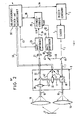
- the embodiment shown in FIG. 5 of a distance measuring device has a transmitter 1 of the first type, which comprises a laser diode and a circuit arrangement which supplies the laser diode with energy, which essentially consists of a "slowly" rechargeable energy store in the form of a capacitance and a controllable electronic switch, which serves to quickly discharge the energy accumulated in the energy store via the transmitter diode to generate a laser light pulse.
- a transmitter 1 of the first type which comprises a laser diode and a circuit arrangement which supplies the laser diode with energy, which essentially consists of a "slowly" rechargeable energy store in the form of a capacitance and a controllable electronic switch, which serves to quickly discharge the energy accumulated in the energy store via the transmitter diode to generate a laser light pulse.
- This switch is controlled by a trigger generator 3, the output signal of which is at least within a short period of time easily reproducible response behavior of the laser diode can also serve as a start or start preparation signal of the respective signal transit time measurement.
- a delay element 2 is connected between the trigger generator 3 and the transmitter 1, which on the one hand ensures that, for example, even when measuring a very short distance, the stop signal for the transit time measurement is at a sufficiently large time interval from the start signal, so that these two signals can be easily processed in succession by one and the same time measurement channel, and on the other hand this causes the signal propagation time measurement to be started before the time, and thus without interference, at which the transmitter on the trigger signal with the generation of a very fast and comparatively large current surge reacted by the transmitter diode, generating very powerful interference signals that would make it extremely difficult to precisely record a start signal for the signal propagation time measurement that was emitted by the transmitter 1 at the same time as or shortly after the light pulse generation.
- the light pulses generated by the transmitter 1 are fed via a transmitter light path 7 to an optical switching and damping unit 8 which contains a light path switch 10 which, depending on its switching state, emits a light pulse emerging from the transmitter light path 7 either into a transmission measuring light path 15 or steers into a device-internal reference light path 11 and can undertake a defined weakening of the light.
- the light path switch 10 can either be formed by a mechanically movable mirror device or by a fixed beam splitter, in the two outgoing light paths of which an attenuator is installed, which can be changed between a very high (preferably infinitely high) and a very small attenuation, then for to provide the switching function, the two D ämpfungsglieder be driven in opposite directions.
- the light pulses fed by the light path switch 10 in its measuring light position into the transmission measuring light path 15 are forwarded to a transmission optics 16, which is shown in simplified form as a single lens and emits the light pulses to the target object 17, the distance of which is to be measured.
- each light pulse reflected by the target object 17 is changed by the receiving optics 18, which is also shown schematically in FIG. 1 as a single lens, via a reception measuring light path 19, an optical variable contained in the optical switching and damping unit 8
- Attenuator 20 and a reception light path 22, which contains an interference filter 21 are fed to a receiver 23 which, for example, as a photoelectric converter, comprises a photodiode with a downstream amplifier and signal generation circuit, which serves to transmit a signal generated by it when a light pulse is received via a line 24 to a time measuring device 25 as a stop signal in order to end the signal transit time measurement carried out by this time measuring device for the light pulse in question.
- This signal transit time measurement had previously been started, as a function of the trigger signal emitted as a function of / from the trigger generator 3, which can be fed to the time measuring device 25 via line 27 as a start signal.
- a line 29 is provided through which corresponding signals can be transmitted from the time measuring device 25 to the trigger generator 3.
- the time measurement results obtained from the time measuring device 25 are fed via lines 28 to a central sequence control, arithmetic and evaluation unit 30 which, on the one hand, determines and displays the corrected distance measured values from these runtime measured values and, on the other hand, controls the functional sequences in the entire measuring device.
- This sequence control, arithmetic and evaluation unit 30 can preferably comprise a microprocessor.
- the light pulses fed into the reference light path 11 by the light path switch 10 in its reference light position pass through an optionally controllable optical damper 33 and are directed at a branching point 35 into the part 22 of the reception light path leading to the receiver 23.
- the reference light pulses traveling in this way from the transmitter 1 to the receiver 23 are subject with respect to the transmitter of the trigger signal and on the receiver side until the stop signal for the time measuring device 25 is generated, the same delay or signal processing times as the measurement light pulses, from which they differ essentially only in terms of the length of the light path traversed between the light path switch 10 and the branching point 35.
- the optical switching and damping unit 8 can be constructed in the manner described above with any known switching and damping devices.
- a particularly advantageous construction of such a switching and damping unit 8 is, however, described in the simultaneously filed German patent application P 32 19 452.8 with the title "Dynamic control arrangement for a distance measuring device" (our symbol M 72).
- a signal exchange between the optical switching and damping unit 8 and the sequence control, arithmetic and evaluation unit 30 takes place via the line 39, which can be multi-core or bidirectional, so that, for example, the current position of the light path switch 10 via line 40 relevant information is transmitted to the sequence control, arithmetic and evaluation circuit 30 and command signals adapted to the respective operating state can be emitted via lines 41 and 42 from the sequence control, arithmetic and evaluation unit 30 to the optical dampers 20 and 33, respectively .
- the receiver comprises 23 comparators which transmit their signals via line 43 to the central sequence control, computing and evaluation unit 30 for further processing.
- the timing circuit 25 may be 23 formed completely single channel in this embodiment as well as the receiver, that is, all of the analog fine time measurements of one and the same Analogmeßvorraum be carried out, the signal processing times rifterscheinept including fluctuations and D because of the difference between quick succession obtained measuring light and Lift out reference light signal propagation times.
- a time measuring device of this type which is preferably used here can be found in German patent application P 32 15 847.5.
- the distance measuring device shown in Fig. 1 works in such a way that the light path switch 10 periodically alternates between the measuring light position and the reference light position.
- the central sequence control, computing and evaluation unit 30 controls the trigger generator 3 via the line 44 so that it transmits the transmitter 1 at the correct times causes light pulses to be emitted which, due to the respective current position of the light path switch 10, are either passed on as measuring or reference light pulses and fed to the receiver 23 with a corresponding attenuation.
- the correct attenuation is first determined with a series of test measurements and, as soon as this is established, preferably a large number of alternating measurement and reference light pulses so quickly given that during this time neither the distance of the target object nor the signal delay times involved in the measurements change. Average values are formed from the transit times obtained in this way and the measured distance value sought is calculated therefrom.
- FIG. 2 The embodiment of a distance measuring device according to the invention shown in FIG. 2 corresponds in many parts, which are also all designated with the same reference numerals, to the embodiment of FIG. 1.
- the distance measuring device does not use a laser diode as transmitter 1, but rather a laser which, on the one hand, because of its significantly higher power, measures far greater distances (from more than 10 km 6 0 to over 100 km) is allowed, but on the other hand has the property that its response delay to the trigger signal, unlike the laser diode, cannot be regarded as constant even over very short periods of time. Rather, with such a laser, changes in the response time of up to several microseconds can occur even with a very fast light pulse sequence from light pulse to light pulse, so that somewhat different signal propagation times have to be measured here if one wants to achieve high measurement accuracy.
- a beam splitter is provided in the transmitter light path 7, which is formed here by a partially transparent mirror 45 which is inclined at 45 ° relative to the optical axis of the transmitter light path 7 and which rectilinearly for the most part, for example 99% of each light pulse emitted by the transmitter 1 passes optical switching and damping unit 8 and deflects only the remaining small part at an angle of 90 ° and feeds into an auxiliary light path 46 running inside the device, which leads via a damping filter 47 and an interference filter 48 to an auxiliary receiver 50.
- This auxiliary receiver 50 differs from the main receiver receiving the reflected measurement light pulses or the reference light pulses / essentially in that, as a photoelectric converter, it does not have a complex avalanche diode but rather a much more cost-effective PIN diode that does not require a high-voltage supply, the latter compared to an avalanche -Diode lower sensitivity is completely sufficient, because a comparatively large brightness is available via the auxiliary light path 46.
- the auxiliary receiver 50 also contains amplifier and processing circuits which make it possible to generate a time-significant output signal which is precisely correlated in time with the arrival of a light pulse and which is fed via line 52 to the time measuring device 25 as a start signal.
- an arrangement is preferably used as the time measurement device 25, in which the fine measurement values for the start signals no longer correlated with the time base signal are determined by another analog measurement device than the fine measurement values of the stop signals.
- Timing arrangement can be found, for example, in DE-OS 28 42 450.
- a reference light part is branched off from each measuring light pulse and fed to its own receiver, the output signal of which serves to start a runtime measurement, which is ended by the output signal of another receiver which receives the measurement light pulse reflected from the target object. Since the start and stop signals for the transit time measurement can follow each other very quickly at short measuring distances, the required fine time measurement is carried out with a separate analog measuring device. There is only one type of light pulse transit time measurement here, namely the transit time measurements for the measurement light pulses . and in addition to the distance sought, the resultant measured value also contains the difference between the reaction and signal processing times of the two channels, this difference being subject to temporal fluctuations and drift phenomena.
- the so-called zero offset of the two channels is measured, that is to say, for example, the two resonant circuits connected downstream of the receiving photodiodes are electrically triggered exactly at the same time, and the resulting transit time difference is measured and subtracted from the previously obtained measurement light pulse transit time value.
- the strongly temperature-dependent response delays of the photodiodes are not recorded.
- two types of light pulse transit time measurements namely signal transit time measurements via the Measuring section 7, 15, 17, 19, 22 and signal propagation time measurements over the reference section 7, 11, 22 are carried out in succession, with each of these measurements using both the optical "channels" and the two analog measuring circuits in such a way that all the delays that occur - and signal processing times go into the same way in the two types of measurements. Because these measurements follow one another so rapidly that the "parasitic" times just mentioned either do not change at all or at best change linearly, the latter drop out completely when the differences and averages are formed to determine a single measured distance value.
- This second embodiment thus represents a quasi single-channel system, in which in particular the reproducibility of the response behavior of the transmitter does not play a role and which largely corresponds in its function and measuring accuracy to the purely single-channel system of the embodiment according to FIG. 1.
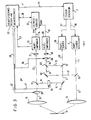
- this variant includes an auxiliary transmitter 55, which can have a considerably lower output since it only serves to generate the reference light pulses.
- the trigger generator 3 controls the two transmitters 1 and 55 alternately via the lines 56 and 57 in accordance with the command signals supplied to it via the line 44, so that the main transmitter 1 generates a measuring light pulse via the measuring path 7, 15, 17, 19 , 22 to the main receiver 23 and once the auxiliary transmitter 55 sends a reference light pulse over the reference path 58, 11, 22 to the main receiver 23.
- a correlation of the trigger signals with a time base signal of the time measuring device 25 does not take place, and in particular a laser with a strongly fluctuating response can be used as the main transmitter 1.
- a signal transit time measurement via the measuring section 7, 15, 17, 19, 22 takes place in such a way that the main transmitter 1 generates a measuring light pulse on the basis of a corresponding trigger signal, the main part of which comprises a first beam splitter 60, for example a partially transparent one, arranged in the output light path 7 of the main transmitter 1 Mirror passes through in a straight line to be emitted to the target object, while a small part of the measurement light pulse is fed from the first beam splitter 60 into a first auxiliary light path 61 and via a totally reflecting deflection mirror 62, a partially transparent coupling mirror 63, an optical path section 64, a controllable damping device 65 and a Interference filter 48 reaches the auxiliary receiver 50.
- a first beam splitter 60 for example a partially transparent one
- the damping device 65 is controlled by the sequence control, computing and evaluation unit 30 via a line 66 so that the amplitude or brightness of the light pulses arriving at the auxiliary receiver 50 is always approximately the same size.
- the auxiliary receiver 50 When the part branched off from the measuring light pulse is received, the auxiliary receiver 50 emits a time-significant signal which is fed to the time measuring device 25 via line 67 as a start signal for the signal transit time measurement in question. Since this start signal is in no way correlated with the time base signal of the time measuring device 25, it can not only be used to start a counting of the periods of the time base signal that provides the rough measurement value for the signal transit time, but it must also be carried out by an analog measurement as the first fine measurement value The time interval of this start signal from a subsequent defined edge of the time base signal can be determined.
- This signal transit time measurement is ended via the measuring section 7, 15, 17, 19, 22 by the output signal which the main receiver 23 emits via the line 24 to the time measuring device 25 when it receives the measuring light pulse coming back from the target object 17. Since this stop signal can follow the start signal very quickly at short measuring distances, the time interval of the stop signal forming the second fine measurement value of this signal transit time measurement is measured from a subsequent defined edge of the time base signal by means of a second analog measuring circuit contained in the time measuring device 25 .
- this signal transit time measurement only includes the response times of the two receivers 23 and 50 and the difference in the signal processing times in the two analog measuring circuits of the time measuring device 25, but not the response time of the main transmitter 1.
- each reference light pulse coupled out by the second beam splitter 70 is fed into a second auxiliary light path 73, which is combined with the light path section 64 leading to the auxiliary receiver 50 via the partially transparent coupling mirror 63.
- the output signal of the auxiliary receiver 50 serves as a start signal and the output signal of the main receiver serves as a stop signal for the time measuring device 25, which in turn takes a three-part time measurement, ie a time measurement comprising two fine measurement values and a coarse measurement value, whereby, as already mentioned, the resulting total measurement value is independent of the response time of the auxiliary transmitter 55 and, moreover, contains the same parasitic variables as the overall measurement value previously obtained Signal transit time measurement over the measuring section.
- the parasitic variables can be completely eliminated according to the invention if the measurements are carried out so quickly in succession that there are no changes in these parasitic ones in the period concerned Sizes occur.
- auxiliary transmitter 55 By triggering the auxiliary transmitter 55 correspondingly more frequently than the main transmitter 1, a largely periodic operation of the auxiliary receiver 50 and the main receiver 23 as well as of the two analog measuring circuits contained in the time measuring device 25 can also be achieved, which leads to the substantial increase already mentioned of measurement accuracy.
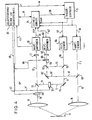
- the variant shown in FIG. 4 is almost identical to the variant according to FIG. 3. It differs from that mainly in its mode of operation, which is made possible by a different control of the time measuring device 25.
- Synchronization signals from the time measuring device 25 are again supplied to the trigger generator 3 via the line 29, so that its trigger signals are strictly synchronized with the time base signal. Since only laser diodes with a short-term reproducible response behavior are used here as transmitters 1 and 55, the signal propagation time measurements can be made as a function of both the measuring path 7, 15, 17, 19, 22 and the reference path 58, 11, 22 starting from the associated trigger signal, dispensing with the first fine measurement formation described above in connection with FIG. 3, which is symbolized in FIG. 4 in that the trigger lines 56, 57 are connected to the start input of the time measuring device 25 .
- the respective signal transit time measurement is then ended with the output signal of the main receiver 23, with a fine measurement value formation again taking place here.
- the response times of the main transmitter 1 and the auxiliary transmitter 55 are also included in the signal transit time values thus obtained, so that all parasitic variables are eliminated by simply forming a difference between a signal transit time value via the measuring section 7, 15, 17, 19, 22 and a signal transit time value over the reference path 58 ', 11, 22 or between corresponding mean values is not completely possible.
- two further signal propagation time measurements must be carried out here via the two auxiliary light paths 7, 61, 64 and 58, 73, 64.
- These signal transit time measurements are also carried out as two-part time measurements, as was described above for the measuring and the reference path. Go into the difference between the two signal transit time measurements in question here in turn, inter alia, the response times of the main transmitter 1 and the auxiliary transmitter 55, so that all parasitic times can be eliminated by forming a difference between the signal propagation time differences mentioned.
- the beam splitters 60 and 70 are operated in conjunction with the controllable damping devices 20, 33 and 65 as light path switches. Should e.g. a signal transit time measurement over the measuring section 7, 15, 17, 19, 22 take place, the first auxiliary light path 61 coupled to the measuring section via the static beam splitter 60 is rendered ineffective in that the damping; device 65 is switched to minimal light transmittance, while the controllable damping device 20, which also serves for dynamic control, can be used to block the measuring light path.
- At least four two-part time measurements are carried out in order to form a distance measurement value, which, although reducing the measurement speed, offers the advantage that the time measurement device only has to comprise a single analog measurement circuit which, like the two receivers 23 and 50, is also strictly periodic can be operated.
- the variant shown in FIG. 5 differs from all of the foregoing primarily in that its reference path 11, which is branched off from the measuring path 7, 15, 17, 19, 22 with the aid of a beam splitter 77, is not at the main receiver 23 but at the auxiliary receiver 50 ends.
- a light pulse is first emitted by the auxiliary transmitter 55 on the basis of a trigger signal synchronized with the time base signal via the line 29, which light pulse is transmitted via the transmitter light path 78 of the auxiliary transmitter 55 its main part passes through a second beam splitter 79 in a straight line and on a device-internal first auxiliary light path 8Q via a totally pure controllable damping unit 65 deflecting deflection mirror 81, / and a partially transparent coupling mirror 82 enters the light path 22 leading to the main receiver 23.
- the time-significant signal generated on receipt of this light pulse by the main receiver 23 is fed to the start and the stop input of the time measuring device 25 via the lines 83, 84 at the same time; however, it is suppressed by an electronic switch (not shown) behind the stop input of the time measuring device 25, so that it is only effective as a start signal.
- time-significant signal is simultaneously supplied via lines 88, 89 to the stop and start inputs of time measuring device 25, but remains ineffective because the inputs are blocked by the electronic switches mentioned above. It is expressly pointed out here that the static Beam splitter 79 works in conjunction with the described operation of the electronic switch of the time measuring device 25 as a light path switch.
- the trigger generator 3 emits a defined number of periods of the time base signal after the above-mentioned trigger signal for the auxiliary transmitter 55, a trigger signal for the main transmitter 1, the light pulse of which is also synchronized with the time base signal, via the transmitter light path 7 and in connection with the controllable damping device 33 or the partially transparent mirror 77 located in the time measuring device 25, the inputs blocking electronic switches operating as a light path switch, reaches the measuring path 15, 17, 19, 22 and to the main receiver, 23f whose output signal as a stop signal via line 83 for the time measuring device 25 takes effect.
- the second measurement value formation now required can also be carried out at very short distances from the same analog measurement circuit as the first fine measurement value formation, since the time interval between the two trigger signals, which according to the invention is an integer multiple of a period of the time base signal, can be chosen to be sufficiently large.
- the auxiliary transmitter is again triggered strictly correlated with the time base signal.
- the small part fed by the beam splitter 79 into the second auxiliary light path 85 which causes the auxiliary receiver 50 to emit a start signal via the line 89, becomes active by a corresponding control of the electronic switch of the time measuring device 25, while line 88 is blocked.
- a three-part signal propagation time measurement begins again, which is ended by a light pulse which is also triggered later by a defined number of periods of the time base signal and which is transmitted from the main transmitter 1 via the transmitter light path 7, the beam splitter 77, the reference light path 11, the coupling mirror 86 and the light path 87 also reaches the auxiliary receiver 50 and causes it to emit a stop signal, while all other lines 89, 83, 84 to the time measuring device 25 are blocked.
- the signal transit time value thus obtained via the reference path 7, 11, 87 again contains only the response behavior of the two transmitters 1 and 55 in terms of parasitic time variables, while the response behavior of the auxiliary receiver 50 and the signal processing time of the analog measurement circuit each eliminate themselves again.
- the influence of the transmitters can also be eliminated by subtracting the signal propagation time values over the measurement and over the reference path if the condition of a fast measurement sequence mentioned several times above is fulfilled.
- the particular advantage of this variant is that the time measuring device only needs to have a single analog measuring circuit, that is to say it works in real single-channel fashion, which ensures particularly good measuring accuracy.
Abstract
Zur Vermeidung der Schwierigkeiten, die bei Entfernungsmessungen nach dem Prinzip der Laufzeitmessung von Lichimpulsen hinsichtlich der exakten Erfassung der tatsächlichen Laufzeit der Messlichtimpulse auftreten, werden gemäss der Erfindung Signal-Laufzeiten gemessen, die neben der reinen Lichtimpuls-Laufzeit auch noch die senderseitige Verzögerungs- und Ansprechzeit sowie die empfängerseitige Signalverarbeitungszeit umfassen. Um von Schwankungen bzw. Drifterscheinungen dieser beiden elektrischen Signal-Laufzeiten unabhängig zu werden, werden wechselweise Signal-Laufzeitmessungen über die Messstrecke und über eine geräteinterne Referenzstrecke durchgeführt, wobei im letzteren Fall die Laufzeit der Referenz-Lichtimpulse aufgrund der fest vorgegebenen Referenz-Lichtweg-Länge genau bekannt ist, so dass die Momentanwerte der in den Signal-Laufzeitmessungen über die Referenzstrecke ebenfalls einhaltenen elektrischen Signal-Verzögerungs- und -Verarbeitungszeiten exakt ermittelt und vom zugehörigen, über die Messstrecke gewonnenen Signal-Laufzeitwert abgezogen werden können.In order to avoid the difficulties that occur with distance measurements based on the principle of the transit time measurement of light pulses with regard to the exact detection of the actual transit time of the measurement light pulses, signal transit times are measured according to the invention, which in addition to the pure light pulse transit time also the transmitter-side delay and response time as well as the receiver-side signal processing time. In order to become independent of fluctuations or drift phenomena of these two electrical signal transit times, signal transit time measurements are carried out alternately over the measurement section and over a device-internal reference section, in the latter case the transit time of the reference light pulses on the basis of the predetermined reference light path length is precisely known, so that the instantaneous values of the electrical signal delay and processing times also observed in the signal transit time measurements over the reference link can be determined exactly and subtracted from the associated signal transit time value obtained over the measurement link.
Description
Die Erfindung betrifft ein Entfernungsmeßverfahren nach dem Prinzip der Laufzeitmessung eines Meßlichtimpulses gemäß dem Oberbegriff von Anspruch 1 sowie eine Vorrichtung zur Durchführung dieses Verfahrens gemäß dem Oberbegriff von Anspruch 14.The invention relates to a distance measuring method based on the principle of measuring the transit time of a measuring light pulse according to the preamble of claim 1 and a device for carrying out this method according to the preamble of claim 14.
Bei Entfernungsmeßgeräten, die nach dem Prinzip der Laufzeitmessung eines Lichtimpulses arbeiten, besteht das grundsätzliche Problem, die Zeitpunkte, in denen die Zeitmeßvorrichtung gestartet bzw. angehalten wird, so mit den Zeitpunkten zu korrelieren, in denen der Meß-' lichtimpuls emittiert bzw. nach seiner Reflexion am Zielgegenstand wieder empfangen wird, daß ein Zeitmeßwert er- , halten werden kann, der mit großer Genauigkeit der Laufzeit des Meßlichtimpulses entspricht und somit eine exakte Entfernungsbestimmung ermöglicht.In the case of distance measuring devices which operate on the principle of measuring the transit time of a light pulse, there is the fundamental problem of correlating the times at which the time measuring device is started or stopped with the times at which the measuring ' light pulse emits or after it Reflection on the target object is received again that a time measurement value can be obtained which corresponds with great accuracy to the transit time of the measurement light pulse and thus enables an exact determination of the distance.
Besonders dann, wenn ein sehr großer Entfernungsmeßbereich, beispielsweise von O bis 100 km und mehr mit einer Genauigkeit von bis zu + 1 mm ausgemessen werden soll, ergeben sich außerordentlich große Schwierigkeiten, da sowohl senderseitig zwischen dem den Sender zur Emission eines Meßlichtimpulses anregenden Trigger-Signal und der tatsächlichen Emission des Lichtimpulses als auch empfägerseitig zwischen Eintreffen des reflektierten Meßlichtimpulses beispielsweise an einem photoelektrischen Detektor und der Erzeugung des zugehörigen Stop-Signals für die Zeitmeßvorrichtung Verzögerungs- und Signalverarbeitungszeiten auftreten, die in der gleichen Größenordnung wie die eigentlich interessierenden "echten" Lichtimpuls-Laufzeiten liegen oder, bei kurzen Entfernungen, diese sogar erheblich übersteigen.Particularly when a very large distance measuring range, for example from 0 to 100 km and more is to be measured with an accuracy of up to + 1 mm, there are extraordinarily great difficulties, since both on the transmitter side between the trigger which excites the transmitter to emit a measuring light pulse Signal and the actual emission of the light pulse as well as on the receiver side between the arrival of the reflected measuring light pulse, for example at a photoelectric detector and the generation of the associated stop signal for the time measuring device, delay and signal processing times occur which are of the same order of magnitude as the "real" light pulse which is actually of interest -Runtimes are or, in the case of short distances, even exceed them considerably.
Es ist klar, daß bei diesen Verhältnissen dann, wenn keine entsprechenden Maßnahmen getroffen werden, sich temperaturbedingte Schwankungen bzw. alterungsabhängige Drifterscheinungen dieser Verzögerungs- und Signalverarbeitungszeiten auf das Meßergebnis so stark auswirken können, daß es unmöglich wird, die obengenannte Meßgenauigkeit zu erzielen.It is clear that under these conditions, if no appropriate measures are taken, there will be temperature-related fluctuations or age-related drift differences These delay and signal processing times can affect the measurement result so strongly that it becomes impossible to achieve the above-mentioned measurement accuracy.
Das Problem, auf der Empfängerseite eine exakte zeitliche Zuordnung zwischen dem Empfangszeitpunkt des reflektierten Lichtimpulses und dem Erzeugungszeitpunkt des Stop-Signals für die Zeitmessung herzustellen, kann durch die in der DE-OS 26 34 627 beschriebene Schaltungsanordnung als prinzipiell gelöst betrachtet werden.The problem of establishing an exact time allocation on the receiver side between the time of reception of the reflected light pulse and the time of generation of the stop signal for the time measurement can be regarded as solved in principle by the circuit arrangement described in DE-OS 26 34 627.
Auf der Senderseite ist die Situation schwieriger, weil die Verzögerungszeit, mit der der Sender auf das Trigger-Signal anspricht, starken Änderungen unterliegen kann, so daß das Trigger-Signal nicht ohne weiteres als mit dem Emissionszeitpunkt exakt korreliertes Start-Signal für die Zeitmeßvorrichtung verwendbar ist.The situation on the transmitter side is more difficult because the delay time with which the transmitter responds to the trigger signal can be subject to strong changes, so that the trigger signal cannot be used as a start signal for the time measuring device which is exactly correlated with the time of emission is.
Zur Vermeidung dieses Problems ist es z.B. aus der US-PS 3 652 161 (entsprechend der deutschen Patentanmeldung P 16 23 564.6) bekannt, aus dem vom Sender emittierten Meßlichtimpuls beispielsweise durch einen teildurchlässigen Spiegel einen Teil abzuzweigen und den so erzeugten Referenzlichtimpuls durch einen Photodetektor in ein mit dem Sendezeitpunkt des Meßlichtimpulses korreliertes Start-Signal für die Laufzeitmessung umzusetzen. Verwen- det man dabei, wie es in obiger Patentschrift beschrieben ist, für Meßlichtimpuls und Referenzlichtimpuls zwei verschiedene Empfänger, so ergeben sich, wenn keine weiteren Maßnahmen ergriffen werden, Schwierigkeiten aus dem unterschiedlichen Ansprechverhalten und den unterschiedlichen Schwankungserscheinungen der Signalverarbeitungszeiten der beiden Empfangskanäle. Führt man andererseits Meßlichtimpuls und Referenzlichtimpuls ein und demselben Empfänger zu, so wird die Messung kleiner Entfernungen schwierig, da sowohl die dem Photodetektor nachgeschaltete Verstärker- und Signalerzeugungsschaltung als auch die Zeitmeßvorrichtung nur solche Signale einwandfrei verarbeiten können, die einen gewissen Mindestabstand aufweisen. Zwar ist es mit entsprechendem Schaltungsaufwand möglich, Zeitmeßvorrichtungen zu bauen, die den Zeitabstand von praktisch beliebig dicht aufeinanderfolgenden Signalen ausmessen können; die dem Photodetektor nachgeordnete Verstärker- und Signalerzeugungsschaltung hat dagegen in jedem Fall eine gewisse Freiwerdezeit, d.h. nach dem Empfang eines Lichtimpulses muß eine bestimmte Mindestzeit verstreichen, bevor ein neuerlicher Impuls einwandfrei verarbeitet werden kann. Hier ist eine untere Grenze für die kleinsten ausmeßbaren Entfernungen gegeben, die durch Maßnahmen an der Verstärker- und Signalerzeugungsschaltung zwar sehr klein gemacht, nicht aber auf Null gebracht werden kann.To avoid this problem, it is known, for example from US Pat. No. 3,652,161 (corresponding to German
Demgegenüber liegt der Erfindung die Aufgabe zugrunde, ein Verfahren und eine Vorrichtung der eingangs genannten Art so weiterzubilden, daß auf einfache Weise und mit großer Genauigkeit Entfernungen über einen weiten Meßbereich hinweg gemessen werden können, dessen untere Grenze praktisch bei Null liegt.In contrast, the invention has for its object to develop a method and an apparatus of the type mentioned in such a way that distances can be measured in a simple manner and with great accuracy over a wide measuring range, the lower limit of which is practically zero.
Zur Lösung dieser Aufgabe sieht die Erfindung die in den Ansprüchen 1 (Verfahren) und 14 (Vorrichtung) niedergelegten Merkmale vor.To achieve this object, the invention provides the features set out in claims 1 (method) and 14 (device).
Diese erfindungsgemäßen Maßnahmen bauen auf der Erkenntnis auf, daß es zur Erzielung einer hohen Meßgenauigkeit nicht unbedingt erforderlich ist, eine genau bekannte und über lange Zeiten hinweg exakt reproduzierbare zeitliche Zuordnung zwischen dem Start-Signal für die Zeitmeßvorrichtung und dem Emissionszeitpunkt des Meßlichtimpulses bzw. dem Empfangszeitpunkt des reflektierten Meßlicht-These measures according to the invention are based on the knowledge that in order to achieve a high measurement accuracy it is not absolutely necessary to have a precisely known and precisely reproducible time association between the start signal for the time measuring device and the emission time of the measurement light pulse or the reception time of the reflected measuring light
impulses und dem Stop-Signal für die Zeitmeßvorrichtung herzustellen. Es wird vielmehr von einem völlig anderen Konzept ausgegangen, bei dem nicht mehr versucht wird, die "reine" Laufzeit eines Meßlichtimpulses zu erfassen. Stattdessen wird bei einem nach dem erfindungsgemäßen Verfahren arbeitenden Meßgerät zur Ermittlung eines einzigen Entfernungsmeßwertes für wenigstens zwei nacheinander und damit voneinander unabhängig erzeugte Lichtimpulse jeweils eine Signal-Laufzeitmessung durchgeführt, wobei der eine dieser wenigstens zwei Lichtimpulse als Meßlichtimpuls über die Meßstrecke, d.h. vom Sender zum Zielgegenstand und von dort zurück zum Empfänger, und der andere als Referenzlichtimpuls über eine geräteintern vom Sender zum Empfänger verlaufende Referenzlichtstrecke in erster Näherung bekannter und konstanter Länge gesandt wird.produce impulses and the stop signal for the time measuring device. Rather, it is based on a completely different concept, in which no more attempts are made to detect the "pure" transit time of a measuring light pulse. Instead, a signal transit time measurement is carried out in a measuring device operating according to the method of the invention for determining a single distance measurement value for at least two light pulses generated in succession and thus independently of one another, one of these at least two light pulses as a measurement light pulse over the measurement path, i.e. from the transmitter to the target object and from there back to the receiver, and the other is sent as a reference light pulse over a device-internal reference light path running from the transmitter to the receiver in a first approximation of known and constant length.
In beiden Fällen liegt das Signal, dessen Laufzeit gemessen wird, für bestimmte Teile dieser Laufzeit in elektrischer Form und für andere Teile dieser Laufzeit in Form eines Lichtimpulses vor.In both cases, the signal, the transit time of which is measured, is in electrical form for certain parts of this transit time and in the form of a light pulse for other parts of this transit time.
Nimmt man an, daß zwischen dem Zeitpunkt, in dem die Laufzeitmessung für den Meßlichtimpuls gestartet wird, und dem Zeitpunkt, in dem der Meßlichtimpuls den Sender verläßt, eine Zeit t1 vergeht (die dann, wenn der letztgenannte Zeitpunkt vor dem erstgenannten liegt, ein negatives Vorzeichen erhält), daß weiterhin der Meßlichtimpuls zum Durchlaufen der Meßstrecke die Zeit tM benötigt und daß zwischen dem Eintreffen des Meßlichtimpulses am Empfänger und der Beendigung der Signal-Laufzeitmessung die Zeit t2 verstreicht, so gilt für den erhaltenen Signal-Laufzeit-Meßwert TM It is assumed that a time t 1 elapses between the point in time at which the measuring time pulse for the measuring light pulse is started and the point in time at which the measuring light pulse leaves the transmitter (which occurs when the last point in time lies before the former) receives a negative sign) that the measuring light pulse still requires the time tM to pass through the measuring section and that the time t 2 elapses between the arrival of the measuring light pulse at the receiver and the end of the signal propagation time measurement, T applies to the signal propagation time measurement value obtained M

Erfindungsgemäß ist es nun zur Erzielung einer hohen Meßgenauigkeit nicht erforderlich, die Zeiten t1 und t2 genau zu kennen und/oder gegen Schwankungen oder Drifterscheinungen in besonderer Weise zu stabilisieren. Es genügt vielmehr, dafür zu sorgen, daß diese beiden Zeiten t1 und t2 ebenfalls in die Signal-Laufzeitmessung des Referenzlichtimpulses eingehen, so daß für den Referenzlichtimpuls gilt:![]()
![]()
Im ersten Fall, d.h. immer dann, wenn der Wechsel zwischen der Messung der Signal-Laufzeit TM über die Meßstrecke und der Messung der Signal-Laufzeit TR über die Referenzstrecke sehr schnell, beispielsweise innerhalb von 50 µs bis 100 µs durchgeführt werden kann und/oder wenn an die Meßgenauigkeit keine extrem hohen Anforderungen gestellt werden, so daß t1 = t'1 und t2 = t'2 gesetzt werden kann, läßt sich die obige Gleichung (2) unmittelbar nach t1 + t2 auflösen und in Gleichung (1) einsetzen, woraus man durch Auflösung der so erhaltenen Gleichung für die eigentlich interessierende, weil allein von der zu messenden Entfernung abhänende Größe tM erhält:![]()
![]()
In all den Fällen, in denen die obige Voraussetzung nicht zulässig ist, weil entweder langsamer umgeschaltet und/ oder eine extrem hohe Meßgenauigkeit angestrebt wird, kann man erfindungsgemäß so vorgehen, daß man zumindest jede Signal-Laufzeitmessung über die Meßstrecke zwischen zwei Signal-Laufzeitmessungen über die Referenzstrecke einschließt. Für die beiden letzteren Signal-Laufzeitmessungen erhält man dann![]()

![]()
Da es immer möglich ist, die beiden Signal-Laufzeitwerte TR1 und TR2 so rasch hintereinander zu ermitteln, daß zwischenzeitliche Änderungen mit hinreichender Näherung als linear betrachtet werden können, genügt eine einfache Interpolation, um eine brauchbare Korrektur des in dieser Zeitspanne gewonnenen Signal-Laufzeitwertes TM durchführen zu können. Nimmt man an, daß die Messung von TM zeitlich genau in der Mitte zwischen den beiden Messungen von TR1 bzw. TR2 erfolgt, so gilt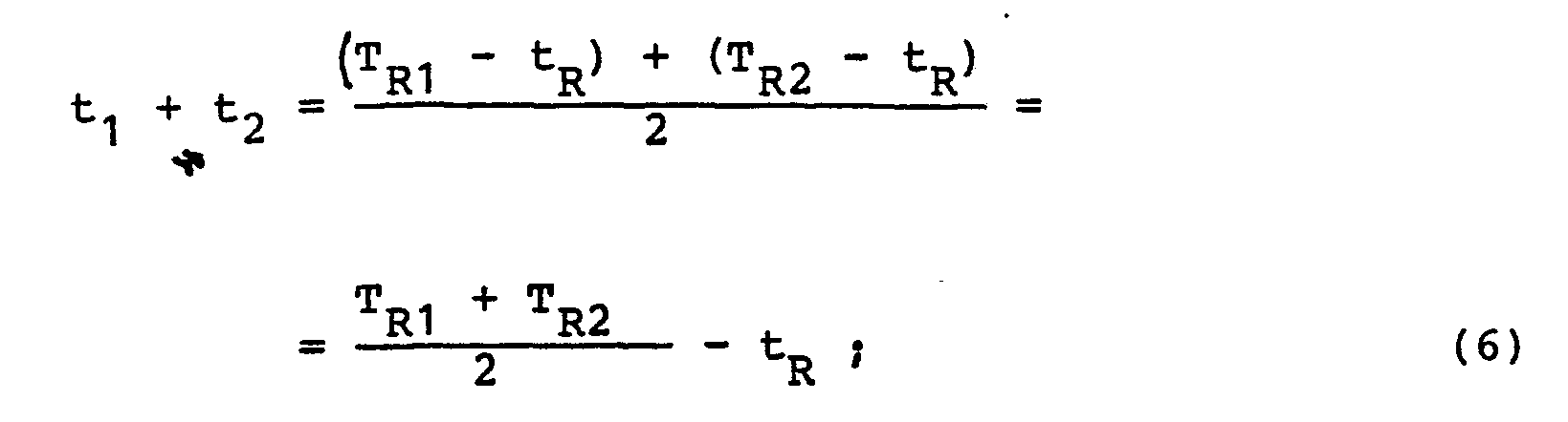

Eine weitere erfindungsgemäße Möglichkeit zur Erzielung einer sehr hohen Meßgenauigkeit bei gleichzeitiger Absenkung der Geschwindigkeit mit der zwischen Signal- Laufzeitmessungen über die Meßstrecke und Signal-Laufzeitmessungen über die Referenzstrecke umgeschaltet wird, besteht darin, alternierend, d.h. ineinander verschachtelt mehrere Messungen über die Meßstrecke und mehrere Messungen über die Referenzstrecke durchzuführen, aus jeder Gruppe der so gewonnenen Meßwerte T bzw. TR die Mittelwerte zu bilden und diese Mittelwerte in die obigen Gleichungen (3) bzw. (7) einzusetzen. Bei dieser Möglichkeit wird allerdings vorausgesetzt, daß sich die Einflußgrößen entweder genügend langsam oder linear ändern.Another possibility according to the invention for achieving a very high measuring accuracy with simultaneous lowering of the speed with which the switch is made between signal propagation time measurements over the measurement section and signal transit time measurements over the reference section consists of alternating, i.e. interleaved, multiple measurements over the measurement section and several measurements over the reference path, to form the mean values from each group of the measured values T or T R obtained in this way and to insert these mean values in the above equations (3) and (7). With this possibility, however, it is assumed that the influencing variables either change slowly enough or linearly.
Eine weitere Voraussetzung dafür, daß das erfindungsgemäße Entfernungsmeßverfahren zu sehr genauen Meßergebnissen führt, liegt darin, daß tR tatsächlich als über lange Zeiträume hinweg unveränderliche Gerätekonstante betrachtet werden kann. Dies bedeutet, daß die Länge des geräteinternen Referenzlichtweges unveränderlich sein muß. Dies läßt sich am einfachsten dadurch erreichen, daß man bei den Signal-Laufzeitmessungen über die Referenzstrecke Lichtimpulse vom Lichtweg-Umschalter im wesentlichen über eine Lichtleitfaser zum Empfänger lenkt, wobei in diesen Lichtweg allenfalls noch ein optischer Z Dämpfer eingeschaltet sein kann. Die Länge einer solchen Lichtleitfaser ist zwar temperaturabhängig, doch ist es beispielsweise möglich, die Temperatur im Geräteinneren fortlaufend zu messen und mit Hilfe dieses Meßwertes eine Korrektur von t durchzuführen.A further prerequisite for the distance measuring method according to the invention leading to very precise measuring results is that t R can actually be regarded as a device constant that is unchangeable over long periods of time. This means that the length of the internal reference light path must be unchangeable. The easiest way to achieve this is to direct light pulses from the light path changeover switch essentially via an optical fiber to the receiver in the signal propagation time measurements over the reference path, an optical path at best in this light path Z damper can be switched on. The length of such an optical fiber is temperature-dependent, but it is possible, for example, to measure the temperature inside the device continuously and to carry out a correction of t using this measured value.
Vorzugsweise wird jedoch die Länge der den Referenzlichtweg im wesentlichen bildenden Lichtleitfaser so kurz gewählt, daß ihre Längenänderung auch bei großen Temperaturschwankungen unterhalb der angestrebten Meßgenauigkeit liegt.However, the length of the optical fiber essentially forming the reference light path is preferably chosen to be so short that its change in length is below the desired measurement accuracy even in the case of large temperature fluctuations.
Verwendet man die Mittelwerte mehrerer Signal-Laufzeit- messungen über die Meß- bzw. die Referenzstrecke zur Berechnung eines einzigen Entfernungsmeßwertes, so besteht eine weitere erfindungsgemäße, zur Erzielung einer sehr hohen Meßgenauigkeit beitragende Maßnahme darin, die Trigger-Signale für den Sender zeitlich so zu legen, daß die alternierenden Meß- und Referenzlichtimpulse am Empfänger möglichst genau periodisch eintreffen. Dies ist dadurch erreichbar, daß man die Trigger-Zeitpunkte für die Meßlichtimpulse nach einem ersten, zur ungefähren Entfernungsbestimmung dienenden Meßlichtimpuls, dessen Laufzeit ansonsten nicht weiter verwendet wird, aufgrund des ungefähren Entfernungsmeßwertes gegen die Trigger-Zeitpunkte für die Referenzlichtimpulse entsprechend der momentanen Länge des Meßlichtweges verschiebt, wobei diese Länge für die Zeit, in der die zu einem Mittelwert zusammenzufassenden Laufzeit-Meßergebnisse gewonnen werden, ohnehin konstant sein muß.If the mean values of a plurality of signal propagation time measurements over the measurement or reference path are used to calculate a single distance measurement value, a further measure according to the invention, which contributes to achieving a very high measurement accuracy, is to time the trigger signals for the transmitter ensure that the alternating measurement and reference light pulses arrive periodically at the receiver as precisely as possible. This can be achieved in that the trigger times for the measuring light pulses after a first measuring light pulse used for approximate distance determination, the duration of which is not otherwise used, due to the approximate distance measured value against the trigger times for the reference light pulses corresponding to the current length of the measuring light path shifts, this length must be constant anyway for the time in which the runtime measurement results to be summarized are obtained.
Dieser möglichst periodische Betrieb der Empfängerseite eines Entfernungsmeßgerätes ist deshalb besonders vorteilhaft, weil die die Lichtimpulse im Empfangskanal weiterverarbeitenden Analogschaltungen, wie alle Analogschaltungen die Eigenschaft besitzen, daß die Größe des von ihnen auf das zu verarbeitende Meßsignal aufgeprägten Fehlers vom Zeitabstand zwischen zwei aufeinanderfolgenden gleichartigen Signalverarbeitungsvorgängen abhängt. Durch die Periodizität der Ansteuerung wird nun erfindungsgemäß erreicht, daß diese Fehler mit derselben Größe in die Laufzeitwerte sowohl der Meßlichtimpulse als auch der zugehörigen Referenzlichtimpulse eingehen und sich somit bei der nachfolgenden Differenzbildung herausheben.This periodic operation of the receiver side of a distance measuring device, which is as periodic as possible, is particularly advantageous because the analog circuits which process the light pulses in the receiving channel, like all Ana Log circuits have the property that the size of the error impressed by them on the measurement signal to be processed depends on the time interval between two successive identical signal processing operations. Due to the periodicity of the control, it is now achieved according to the invention that these errors with the same magnitude are included in the runtime values of both the measurement light pulses and the associated reference light pulses and thus stand out during the subsequent difference formation.
Darüber hinaus findet in der Zeitmeßvorrichtung eines hier in Rede stehenden Entfernungsmeßgerätes im allgemeinen ein Zeitbasissignal Verwendung, das an den verschiedensten Stellen zum Einsatz kommt und daher unver- meidlicherweise auf praktisch allen Leitungen als, wenn f auch sehr kleines, periodisch schwankendes Störsignal vorhanden ist.In addition, a time base signal is generally used in the time measuring device of a distance measuring device in question, which is used in the most varied of locations and is therefore inevitably present on practically all lines as a, albeit very small, periodically fluctuating interference signal.
Betreibt man nun die Anordnung nicht mit einer beliebigen Periodizität, sondern mit einer Folgefrequenz, die ein ganzzahliges Vielfaches der Frequenz des Zeitbasissignals beträgt, so gehen auch die durch das Zeitbasissignal verursachten Störspannungen in die Analogsignale mit gleicher Amplitude ein und fallen daher bei den nachfolgenden Differenzbildungen wieder heraus.If the arrangement is not operated with any periodicity, but with a repetition frequency that is an integral multiple of the frequency of the time base signal, then the interference voltages caused by the time base signal also enter the analog signals with the same amplitude and therefore fall again in the subsequent differences out.
Wie bereits erwähnt, ist eine wesentliche Voraussetzung des erfindungsgemäßen Verfahrens, daß dafür gesorgt wird, daß in die gemessenen Signal-Laufzeitwerte TM bzw. TR für zusammengehörende Meß- bzw. Referenzlichtimpulse die Zeiten t1 und t2, in denen das jeweilige Signal in elektrischer Form vorliegt und die auch die für das Umsetzen sowohl des elektrischen Signals in ein optisches Signal als auch des optischen Signals in die elektrische Form erforderlichen Ansprechzeiten enthalten, in gleicher Weise eingehen.As already mentioned, an essential prerequisite of the method according to the invention is to ensure that the times t 1 and t 2 in which the respective signal occurs in the measured signal propagation time values T M and T R for associated measurement and reference light pulses is in electrical form and which also contain the response times required for converting both the electrical signal into an optical signal and the optical signal into the electrical form, in the same way.
Zur Erfüllung dieser Bedingung sind gemäß der Erfindung in Abhängigkeit von der Art des jeweils verwendeten Senders zwei geeignete Lösungswege vorgesehen.To meet this condition, two suitable solutions are provided according to the invention depending on the type of transmitter used.
Die eine Senderart, deren typischer Vertreter eine Laser- Diode ist, zeichnet sich dadurch aus, daß die Reaktionszeit, die zwischen der Zuführung eines Trigger-Signals zum Sender und der Erzeugung eines Lichtimpulses vergeht, zumindest für die kurzen Zeiträume, die für die Durchführung der zu einem Entfernungsmeßwert beitragenden Signal-Laufzeitmessungen benötigt werden, mit ausreichend guter Genauigkeit reproduzierbar ist, wenn man für eine geeignete konstante Versorgungsspannung der Laser-Diode sorgt.One type of transmitter, the typical representative of which is a laser diode, is characterized in that the reaction time that elapses between the supply of a trigger signal to the transmitter and the generation of a light pulse, at least for the short periods of time required for the implementation of the Signal time-of-flight measurements contributing to a distance measurement value are required and can be reproduced with sufficient accuracy if a suitable constant supply voltage for the laser diode is provided.
Diese Reproduzierbarkeit der Reaktionszeit des Senders bzw. als Start-Vorbereitungssignal ermöglicht es, als Start-Signal für die Zeitmeßschaltung sowohl bei den Meßlichtimpulsen als auch bei den Referenzlichtimpulsen das vom Trigger-Generator abgegebene Trigger- Signal zu verwenden, das dem Sender vorzugsweise um eine vorbestimmte Verzögerung r später als der Zeitmeßschaltung zugeführt wird.This reproducibility of the response time of the transmitter or as a start preparation signal makes it possible to use the trigger signal emitted by the trigger generator as a start signal for the time measurement circuit both for the measurement light pulses and for the reference light pulses, which preferably gives the transmitter a predetermined amount Delay r is supplied later than the time measuring circuit.
In diesem Fall, in dem die Zeitmessung vor der Erzeugung des Lichtimpulses gestartet wird, ist also die in den obigen Gleichungen auftretende Signallaufzeit t1 positiv und umfaßt'im wesentlichen die zusätzliche Verzögerungszeit τ und die Ansprechverzögerung des Senders.In this case, in which the time measurement is started before the generation of the light pulse, the signal propagation time t 1 occurring in the above equations is positive and essentially comprises the additional delay time τ and the response delay of the transmitter.
Beide Zeiten sind hinsichtlich ihrer mittelfristigen Konstanz und langfristigen Driftfreiheit völlig unkritisch, da davon ausgegangen werden kann, daß sie sich beide in dem kurzen, für die Durchführung der Messungen für einen Entfernungsmeßwert benötigten Zeitraum entweder gar nicht oder allenfalls linear ändern, wobei letzteres durch eine entsprechende Interpolation berücksichtigt werden kann.Both times are completely uncritical with regard to their medium-term consistency and long-term freedom from drift, since it can be assumed that they either do not change at all or only change linearly in the short period of time required to carry out the measurements for a distance measurement, the latter by a corresponding one Interpolation can be taken into account.
Ein wesentlicher Vorteil der zusätzlichen, elektronisch erzeugten Verzögerung T besteht darin, daß sie so groß gewählt werden kann, daß der Abstand zwischen Start- und Stop-Signal sowohl bei den Messungen über die möglichst kurze Referenzstrecke als auch bei der Ausmessung sehr kurzer Entfernungen immer groß genug ist, um auch von einer einfach aufgebauten Zeitmeßschaltung ohne weiteres gemessen werden zu können.A major advantage of the additional, electronically generated delay T is that it can be chosen so large that the distance between the start and stop signal is always large, both when measuring over the shortest possible reference distance and when measuring very short distances is enough to be able to be easily measured even by a simple time measurement circuit.
Ein weiterer Vorteil des erfindungsgemäß vorgesehenen Verzögerungsgliedes ist darin zu sehen, daß der Start jeder Signal-Laufzeitmessung, der die zeitlich exakte Erfassung einer Flankeeinesim allgemeinen impulsförmi- gen Signals erforderlich macht, in einem Zeit- ; raum stattfindet, in dem der Sender das Trigger-Signal noch nicht erhalten hat. Der Sender reagiert nämlich auf dieses Trigger-Signal mit der Erzeugung eines sehr schnellen und vergleichsweise großen Stromstoßes durch die Sendediode, so daß sehr kräftige Störsignale erzeugt werden, die es außerordentlich schwierig machen würden, einen in diesen Zeitraum fallenden Startzeitpunkt der Signal-Laufzeitmessung zeitlich genau festzulegen.Another advantage of the delay element provided according to the invention can be seen in the fact that the start of each signal propagation time measurement, which requires the exact acquisition of an edge of a generally pulse-shaped signal, in one time; room takes place in which the transmitter has not yet received the trigger signal. The transmitter responds to this trigger signal by generating a very fast and comparatively large surge of current through the transmitter diode, so that very strong interference signals are generated which would make it extremely difficult to exactly timed a start time of the signal propagation time measurement falling within this period to be determined.
Bei einem Verfahren, bei dem jede Signal-Laufzeitmessung durch das auch dem Sender zugeführte, mit dem Zeitbasissignal nicht korrelierte Trigger-Signal gestartet wird, d.h. bei völlig freilaufendem Zeitbasissignal ist es erforderlich, zur Ermittlung einer jeden Signallaufzeit eine vollständige dreiteilige Zeitmessung durchzuführen, d.h. mit einer beispielsweise als Zeit/Amplituden-Wandlerschaltung aufgebauten Analogmeßschaltung als ersten Feinmeßwert den Zeitabstand zu messen, den das TriggersignalIn a method in which each signal transit time measurement is started by the trigger signal which is also correlated to the transmitter and is not correlated with the time base signal, i.e. with a completely free-running time base signal, it is necessary to carry out a complete three-part time measurement to determine each signal transit time, i.e. with an analog constructed, for example, as a time / amplitude converter circuit measuring circuit as the first fine measurement to measure the time interval that the trigger signal
von einer definierten Flanke des Zeitbasissignals aufweist, als zweiten Feinmeßwert mit derselben Analogmeßvorrichtung den Zeitabstand zu messen, den das jeweilige nach Eintreffen des Lichtimpulses beim Empfänger zum Anhalten der Zeitmessung erzeugte zeitsignifikante Stopsignal von einer definierten Flanke des Zeitbasissignals besitzt und als Grobmeßwert die Perioden des Zeitbasissignals abzuzählen, die zwischen den beiden ebengenannten Flanken liegen. Aus diesen drei Meßwerten kann dann die Laufzeit eines Einzelsignals berechnet werden, so daß also zur Ermittlung der Signal-Laufzeitdifferenz eines Meßlichtimpulses und eines Referenzlichtimpulses vier Feinmeßwert- und zwei Grobmeßwertbildungen erfor- w derlich sind.of a defined edge of the time base signal, using the same analog measuring device as the second fine measurement value to measure the time interval that the time-significant stop signal generated after the arrival of the light pulse at the receiver for stopping the time measurement has a defined edge of the time base signal and to count the periods of the time base signal as a rough measurement value that lie between the two edges just mentioned. The transit time of an individual signal can then be calculated from these three measured values, so that four fine measurement and two coarse measurement values are required to determine the signal transit time difference of a measurement light pulse and a reference light pulse.
Neben dem erhöhten meßtechnischen Aufwand ergibt sich dabei der Nachteil, daß die Analogmeßvorrichtung und der gesamte Meßkanal nicht mit konstanter Frequenz betrieben werden können, weil die auszumessenden Laufzeiten das interessierende Meßergebnis enthalten und damit veränderlich sind und die Analogmeßvorrichtung bei einer dreiteiligen Zeitmessung im allgemeinen in kürzeren Zeitabständen betrieben wird als von einer dreiteiligen Zeitmessung.zur nächsten. Dieser aperiodische Betrieb des Meßkanals kann aber, wie bereits erwähnt, eine Verschlechterung der Genauigkeit der so erzielten Meßergebnisse zur Folge haben.In addition to the increased expenditure on measurement technology, there is the disadvantage that the analog measurement device and the entire measurement channel cannot be operated at a constant frequency, because the transit times to be measured contain the measurement result of interest and are therefore variable, and the analog measurement device in a three-part time measurement generally in shorter time intervals is operated as from a three-part timekeeping. to the next. However, as already mentioned, this aperiodic operation of the measurement channel can result in a deterioration in the accuracy of the measurement results obtained in this way.
Eine besonders bevorzugte Variante des erfindungsgemäßen Verfahrens bietet demgegenüber die Möglichkeit, die Trigger-Signale mit dem Zeitbasissignal phasenstarr korreliert zu erzeugen. In diesem Fall dient das Triggersignal nicht mehr als eigentliches Start-Signal der Signal-Laufzeitmessung sondern nur noch als Vorbereitungssignal für eine allenfalls erforderliche Grobzeitmessung, die durch Abzählen der Flanken des Zeitbasissignals erfolgt und mit einer in einer definierten Korrelation mit dem Triggersignal stehenden, beispielsweise mit der 5-ten auf das Trigger-Signal folgenden Flanke des Zeitbasis- signals beginnt. Es genügt also, unter Wegfall der oben beschriebenen jeweiligen erstenIn contrast, a particularly preferred variant of the method according to the invention offers the possibility of generating the trigger signals in a phase-locked correlation with the time base signal. In this case, the trigger signal no longer serves as the actual start signal of the signal transit time measurement, but only as a preparation signal for a rough time measurement that may be necessary, which is done by counting the edges of the time base signal and with one in one defined correlation with the trigger signal, for example with the 5th edge of the time base signal following the trigger signal. It is therefore sufficient to omit the respective first described above
Feinmeßwertbildung für einen Entfernungsmeßwert nur den Grobmeßwert für die Laufzeit wenigstens eines Meßlichtimpulses und, falls dieser nicht als Gerätekonstante betrachtet werden kann, den Grobmeßwert für die Laufzeit eines Referenzlichtimpulses sowie die "zweiten" Feinmeßwerte für die Laufzeiten aller Lichtimpulse zu ermitteln, um hieraus die gesuchte Laufzeitdifferenz mit der Genauigkeit, mit der die Periode des Zeitbasissignals konstant und bekannt ist, zu erhalten. Durch den Wegfall der "vorderen" Feinmeßwertbildungen ist es möglich, durch eine entsprechende Wahl der Zeitpunkte, in denen die Trigger-Signale erzeugt werden, die Lichtimpulse in der oben beschriebe- nen Weise am Empfänger in strenger Periodizität zu erhalten.Fine measurement value formation for a distance measurement value only the rough measurement value for the running time of at least one measuring light pulse and, if this cannot be regarded as a device constant, the rough measuring value for the running time of a reference light pulse as well as the "second" fine measurement values for the running times of all light pulses in order to determine the runtime difference sought from this with the accuracy with which the period of the time base signal is constant and known. By eliminating the "front" fine measurement value formation, it is possible to obtain the light pulses in a strict periodicity in the manner described above at the receiver by a corresponding choice of the times at which the trigger signals are generated.
Die andere Senderart, deren typischer Vertreter ein Gas- bzw. Festköper-Laser ist, besitzt dagegen die Eigenschaft, daß die Reaktionszeit von Lichtimpuls zu Lichtimpuls auch dann, wenn die betreffenden Lichtimpulse sehr schnell hintereinander erzeugt werden, in so erheblichem Maße schwanken kann, daß ein Start der Laufzeitmessung durch das Trigger-Signal zu untragbaren Meßfehlern führen würde. Daher wird im Rahmen des erfindungsgemäßen Konzeptes für derartige Sender der Start der Signal-Laufzeitmessung sowohl für jeden Meßlichtimpuls als auch für jeden Referenzlichtimpuls mit Hilfe des Ausgangssignals eines Hilfsempfängers bewirkt, dem über einen geräteinternen Start-Lichtweg ein ausgekoppelter Teil des jeweiligen Lichtimpulses zugeführt wird und der hierauf ein zeitsignifikantes Ausgangssignal abgibt.The other type of transmitter, the typical representative of which is a gas or solid-state laser, on the other hand has the property that the response time from light pulse to light pulse can fluctuate to such an extent that even if the light pulses in question are generated very quickly in succession a start of the runtime measurement by the trigger signal would lead to intolerable measurement errors. Therefore, in the context of the concept according to the invention for such transmitters, the start of the signal transit time measurement is effected both for each measurement light pulse and for each reference light pulse with the aid of the output signal of an auxiliary receiver, to which a decoupled part of the respective light pulse is supplied via an internal start light path and which then outputs a time-significant output signal.
In diesem Fall, in welchem die Zeitmessung nach der Erzeugung des jeweiligen Lichtimpulses gestartet wird, ist die Zeit t1 negativ und enthält die Laufzeit des Teil-Lichtimpulses vom Sender zum Hilfsempfänger sowie die Reaktionszeit des Hilfsempfängers. Diese Teile von t sind aber,wieder für die kurzen zu betrachtenden Zeiträume konstant oder zumindest linear veränderlich, so daß wiederum die obigen Gleichungen Verwendung finden können. Entscheidend ist, daß auch hier sämtliche möglichen Verzögerungen in gleicher Weise zumindest in die Mittelwerte der Laufzeiten von Meßlichtimpulsen und Referenzlichtimpulsen eingehen und daher bei der entsprechenden Differenzbil- dung herausfallen.In this case, in which the time measurement is started after the generation of the respective light pulse, the time t 1 is negative and contains the transit time of the partial light pulse from the transmitter to the auxiliary receiver and the reaction time of the auxiliary receiver. These parts of t are, however, constant or at least linearly variable again for the short periods to be considered, so that again the above equations can be used. The decisive factor is that here also all possible delays at least respond in the same way in the mean values of the transit times of Meßlichtimpulsen and reference light pulses and therefore on the corresponding D-making ifferenzbil- fall out.
Eine phasenstarre Korrelation zwischen den Triggersignalen und dem Zeitbasissignal der Zeitmeßschaltung ist hier wegen des schwankenden Reaktionsverhaltens des Senders nicht sinnvoll. Aus diesem Grund muß zumindest für jede Laufzeit-; messung für einen Meßlichtimpuls eine dreiteilige, zu zwei Feinmeßwerten und einem Grobmeßwert führende Zeitmessung durchgeführt werden, während für die Referenzlichtimpulse unter Umständen nur die Feinmeßwerte bestimmt werden müssen, wenn der Grobmeßwert als Gerätekonstante betrachtet werden kann. Insgesamt ergibt sich hier eine etwas geringere absolute Meßgenauigkeit als bei den Sendern der ersten Art, was aber durch die wesentlich höhere Leistung und damit erheblich vergrößerte maximale Reichweite dieser Sender zweiter Art bezüglich der relativen Genauigkeit mehr als ausgeglichen wird.A phase-locked correlation between the trigger signals and the time base signal of the time measuring circuit is not useful here because of the fluctuating response behavior of the transmitter. For this reason, at least for each term; measurement for a measurement light pulse, a three-part time measurement leading to two fine measurement values and a coarse measurement value is carried out, while under certain circumstances only the fine measurement values need to be determined for the reference light pulses if the coarse measurement value can be regarded as a device constant. Overall, the absolute accuracy of measurement is somewhat lower than that of the transmitters of the first type, but this is more than compensated for by the considerably higher performance and thus considerably increased maximum range of these transmitters of the second type with respect to the relative accuracy.
Um auch beliebig kurze Entfernungen messen und insbesondere einen kurzen Referenzlichtweg verwenden zu können, wird bei der mit einem Hilfsempfänger arbeitenden Version eines erfindungsgemäßen Entfernungsmeßgerätes vorzugsweise eine Zeitmeßvorrichtung verwendet, die hinsichtlich der Feinmeßwertbildung das Start- und das Stop-Signal für die Laufzeitmessung jeweils in einem eigenen Analog-Meßkanal verarbeitet. Eine derartige Zeitmeßvorrichtung ist beispielsweise in der DE-OS 28 42 450 beschrieben.In order to be able to measure distances as short as desired and in particular to be able to use a short reference light path, a time measuring device is preferably used in the version of a distance measuring device according to the invention which works with an auxiliary receiver and which, with regard to the formation of fine values, the start and stop signals for the transit time measurement each in their own Analog measuring channel processed. Such a time measuring device is described for example in DE-OS 28 42 450.
Dies bietet den Vorteil, daß auch hier wieder die Trigger-Impulse zeitlich so gesteuert werden können, daß die Lichtimpulse an jedem der Empfänger periodisch eintreffen, so daß die durch die analogen Signalverarbeitungskanäle eingeführten Fehler klein gehalten werden. Das schwankende Reaktionsverhalten des Sendes läßt zwar eine hochgenaue Periodizität nicht zu, doch bleiben die Abweichungen bei der ohnehin begrenzten maximalen Lichtimpuls-Folgefrequenz derartiger Sender im Bereich von einigen Promille oder weniger, so daß sich durch die erfindungsgemäße zeitliche Steuerung der Triggersignale aus den bereits oben genannten Gründen eine wesentliche Verbesserung der Meßgenauigkeit erzielen läßt.This offers the advantage that the trigger pulses can be controlled in such a way that the light pulses arrive periodically at each of the receivers so that the errors introduced by the analog signal processing channels are kept small. The fluctuating response behavior of the transmitter does not permit a highly precise periodicity, but the deviations in the anyway limited maximum light pulse repetition frequency of such transmitters remain in the range of a few parts per thousand or less, so that the trigger signals according to the invention are based on those already mentioned above Reasons can achieve a significant improvement in measurement accuracy.
Die Erfindung wird im folgenden anhand von Ausführungsbeispielen unter Bezugnahme auf die Zeichnung beschrieben; in dieser zeigt:
- Fig. 1 eine erste Ausführungsform,
- Fig. 2 eine zweite Ausführungsform,
- Fig. 3 eine dritte Ausführungsform,
- Fig. 4 eine vierte Ausführungsform und
- Fig. 5 eine fünfte Ausführungsform eines erfindungsgemäßen Entfernungsmeßgerätes.
- 1 shows a first embodiment,
- 2 shows a second embodiment,
- 3 shows a third embodiment,
- Fig. 4 shows a fourth embodiment and
- Fig. 5 shows a fifth embodiment of a distance measuring device according to the invention.
Die in Fig. 5 wiedergegebene Ausführungsform eines nach dem Prinzip der Lichtimpuls-Laufzeitmessung arbeitenden, erfindungsgemäßen Entfernungsmeßgerätes besitzt einen Sender 1 der ersten Art, der eine Laserdiode und eine die Laserdiode mit Energie versorgende Schaltungsanordnung umfaßt, die im wesentlichen aus einem "langsam" aufladbaren Energiespeicher in Form einer Kapazität und einem steuerbaren elektronischen Schalter besteht, der dazu dient, die im Energiespeicher angesammelte Energie schnell über die Sendediode zur Erzeugung eines Laser-Lichtimpulses zu entladen.The embodiment shown in FIG. 5 of a distance measuring device according to the principle of light pulse propagation time measurement has a transmitter 1 of the first type, which comprises a laser diode and a circuit arrangement which supplies the laser diode with energy, which essentially consists of a "slowly" rechargeable energy store in the form of a capacitance and a controllable electronic switch, which serves to quickly discharge the energy accumulated in the energy store via the transmitter diode to generate a laser light pulse.
Die Ansteuerung dieses Schalters erfolgt durch einen Trigger-Generator 3, dessen Ausgangssignal wegen des zumindest innerhalb kurzer Zeiträume gut reproduzierbaren Ansprechverhaltens der Laser-Diode gleichzeitig auch als Start- bzw. Startvorbereitungs-Signal der jeweiligen Signal-Laufzeitmessung dienen kann. Zwischen den Trigger-Generator 3 und den Sender 1 ist ein Verzögerungsglied 2 geschaltet, das einerseits dafür sorgt, daß beispielsweise auch beim Ausmessen einer sehr kurzen Entfernung das Stop- signal für die Laufzeitmessung einen genügend großen zeitlichen Abstand vom Startsignal aufweist, sodaß diese beiden Signale von ein und demselben Zeitmeßkanal ohne weiteres nacheinander verarbeitet werden können, und das andererseits bewirkt, daß die Signal-Laufzeitmessung vor dem Zeitpunkt und damit störungsfrei begonnen wird, in welchem der Sender auf das Trigger-Signal mit der Erzeugung eines sehr schnellen und vergleichsweise großen Stromstoßes durch die Sendediode reagiert, wobei sehr kräftige Störsignale erzeugt werden, die es außerordentlich schwierig machen würden, ein genau gleichzeitig mit oder kurz nach der Lichtimpuls-Erzeugung durch den Sender 1 abgegebenes Start-Signal für die Signal-Laufzeitmessung zeitlich exakt zu erfassen.This switch is controlled by a trigger generator 3, the output signal of which is at least within a short period of time easily reproducible response behavior of the laser diode can also serve as a start or start preparation signal of the respective signal transit time measurement. A
Die vom Sender 1 erzeugten Lichtimpulse werden über einen Sender-Lichtweg 7 einer optischen Schalt- und Dämpfungseinheit 8 zugeführt, die einen Lichtwegumschalter 10 enthält, der je nach seinen Schaltzustand einen aus dem Sender-Lichtweg 7 austretenden Lichtinpuls entweder in einen Sende-Meßlichtweg 15 oder in einen geräteinternen Referenzlichtweg 11 lenkt und dabei eine definierte Schwächung des Lichtes vornehmen kann.The light pulses generated by the transmitter 1 are fed via a transmitter light path 7 to an optical switching and damping unit 8 which contains a light path switch 10 which, depending on its switching state, emits a light pulse emerging from the transmitter light path 7 either into a transmission measuring
Der Lichtwegumschalter 10 kann entweder von einer mechnisch beweglichen Spiegelvorrichtung oder von einem feststehenden Strahlenteiler gebildet werden, in dessen zwei abgehende Lichtwege jeweils ein Dämpfungsglied eingebaut ist, das zwischen einer sehr hohen (vorzugsweise unendlich hohen) und einer sehr kleinen Dämpfung veränderbar ist, wobei dann zur Erzielung der Umschaltfunktion die beiden Dämpfungsglieder gegensinnig angesteuert werden.The light path switch 10 can either be formed by a mechanically movable mirror device or by a fixed beam splitter, in the two outgoing light paths of which an attenuator is installed, which can be changed between a very high (preferably infinitely high) and a very small attenuation, then for to provide the switching function, the two D ämpfungsglieder be driven in opposite directions.
Die vom Lichtwegumschalter 10 in seiner Meßlichtstellung in den Sende-Meßlichtweg 15 eingespeisten Lichtimpulse werden zu einer Sendeoptik 16 weitergeleitet, die vereinfacht als einzelne Linse dargestellt ist und die Lichtimpulse zum Zielgegenstand 17 aussendet, dessen Entfernung gemessen werden soll.The light pulses fed by the light path switch 10 in its measuring light position into the transmission measuring
Der vom Zielgegenstand 17 reflektierte Teil eines jeden Lichtimpulses wird von der in Fig. 1 ebenfalls schematisch als einzelne Linse dargestellten Empfangsoptik 18 über einen Enpfangs-Meßlichtweg 19, einen in der optischen Schalt- und Dämpfungseinheit 8 enthaltenen, veränderbaren optischen Dämpfer 20 und einen Empfangslichtweg 22, der ein Interferenzfilter 21 enthält, einem Empfänger 23 zugeführt, der beispielsweise als lichtelektrischer Wandler eine Photodiode mit einer nachgeschalteten Verstärker- und Signalerzeugungsschaltung umfaßt, die dazu dient, ein von ihr beim Empfang eines Lichtimpulses erzeugtes Signal über eine Leitung 24 einer Zeitmeßvorrichtung 25 als Stop-Signal zuzuführen, um die von dieser Zeitmeßvorrichtung durchgeführte Signal-Laufzeitmessung für den betreffenden Lichtimpuls zu beenden. Diese Signal-Laufzeitmessung war zuvor, keit von dem wie oben erwähnt, in Abhängig/vom Trigger-Generator 3 abgegebenen Triggersignal begonnen worden, das der Zeitmeßvorrichtung 25 über die Leitung 27 als Start-Signal zuführbar ist.The part of each light pulse reflected by the
Für den Fall, daß die Ausgangssignale des Trigger-Genera- tors 3 mit einem in der Zeitmeßvorrichtung 25 erzeugten Zeitbasissignal synchronisiert werden sollen, ist eine Leitung 29 vorgesehen, durch die entsprechende Signale von der Zeitmeßvorrichtung 25 zum Trigger-Generator 3 übertragen werden können.In the event that the output signals of the trigger generator 3 are to be synchronized with a time base signal generated in the
Die von der Zeitmeßvorrichtung 25 gewonnenen Zeitmeßergebnisse werden über Leitungen 28 einer zentralen Ablaufsteuerungs-, Rechen- und Auswerte-Einheit 30 zugeführt, die einerseits aus diesen Laufzeit-Meßwerten die korrigierten Entfernungsmeßwerte ermittelt und zur Anzeige bringt und die andererseits die Funktionsabläufe im gesamten Meßgerät steuert. Vorzugsweise kann diese Ablaufsteuerungs-, Rechen- und Auswerte-Einheit 30 einen Mikroprozessor umfassen.The time measurement results obtained from the
Die vom Lichtwegumschalter 10 in seiner Referenzlichtstellung in den Referenzlichtweg 11 eingespeisten Lichtimpulse durchlaufen einen gegebenenfalls steuerbaren optischen Dämpfer 33 und werden an einer Verzweigungsstelle 35 in den zum Empfänger 23 führenden Teil 22 des Empfangslichtweges geleitet. Die auf diesem Weg vom Sender 1 zum Empfänger 23 laufenden Referenz-Lichtimpulse unterliegen senderseitig bezüglich des Triggersignals und empfängerseitig bis zur Erzeugung des Stop-Signals für die Zeitmeßvorrichtung 25 denselben Verzögerung- bzw. Signalverarbeitungszeiten wie die Meßlichtimpulse, von denen sie sich im wesentlichen lediglich hinsichtlich der Länge des zwischen dem Lichtwegumschalter 10 und der Verzweigungsstelle 35 durchlaufenen Lichtweges unterscheiden. Da die Länge dieses Referenzlichtweges 11 und damit auch die für sein Durchlaufen benötigte Zeit sehr genau bekannt ist, können mit Hilfe der Signal-Laufzeitmessung über die Referenzlichtstrecke die oben erwähnten, auch bei den Signal-Laufzeitmessungen über die Meßstrecke wirksamen Verzögerungs- und Signalverarbeitungszeiten durch eine Differenzbildung der jeweiligen Meßwerte eliminiert werden.The light pulses fed into the
Grundsätzlich kann die optische Schalt- und Dämpfungseinheit 8 in der oben beschriebenen Weise mit beliebigen be- · kannten Schalt- und Dämpfungsvorrichtungen aufgebaut sein. Ein besonders vorteilhafter Aufbau einer solchen Schalt- und Dämpfungseinheit 8 ist jedoch in der gleichzeitig eingereichten deutschen Patentanmeldung P 32 19 452.8 mit dem Titel "Dynamik-Steuerungsanordnung für ein Entfernungsmeßgerät" (Unser Zeichen M 72) beschrieben.In principle, the optical switching and damping unit 8 can be constructed in the manner described above with any known switching and damping devices. A particularly advantageous construction of such a switching and damping unit 8 is, however, described in the simultaneously filed German patent application P 32 19 452.8 with the title "Dynamic control arrangement for a distance measuring device" (our symbol M 72).
Ein Signalaustausch zwischen der optischen Schalt- und Dämpfungseinheit 8 und der Ablaufsteuerungs-, Rechen- und Auswerte-Einheit 30 erfolgt über die Leitung 39, die mehradrig oder bidirektional ausgebildet sein kann, so daß beispielswei% über die Leitung 40 die momentane Stellung des Lichtwegumschalters 10 betreffende Informationen an die Ablaufsteuerungs-, Rechen- und Auswerte-Schaltung 30 übermittelt und über die Leitungen 41 und 42 dem jeweiligen Betriebszustand angepaßte Befehlssignale von der Ablaufsteuerungs-, Rechen- und Auswerte-Einheit 30 an die optischen Dämpfer 20 bzw. 33 abgegeben werden können.A signal exchange between the optical switching and damping unit 8 and the sequence control, arithmetic and
Zur Ermittlung der erforderlichen Dämpfung der Lichtimpulse und zur Anpassung der Amplituden der Referenzlichtimpulse an die der zugehörigen Meßlichtimpulse umfaßt der Empfänger 23 Komparatoren, die ihre Signale über die Leitung 43 an die zentrale Ablaufsteuerungs-, Rechen- und Auswerteeinheit 30 zur weiteren Verarbeitung übermitteln.To determine the required damping of the light pulses and to adapt the amplitudes of the reference light pulses to those of the associated measurement light pulses, the receiver comprises 23 comparators which transmit their signals via
Die Zeitmeßschaltung 25 kann bei diesem Ausführungsbeispiel ebenso wie der Empfänger 23 vollständig einkanalig ausgebildet sein, d.h., daß alle analogen Feinzeitmessungen von ein und derselben Analogmeßvorrichtung durchgeführt werden, deren Signalverarbeitungszeiten einschließlich der Schwankungen und Drifterscheinungen sich aufgrund der Differenzbildung zwischen schnell hintereinander gewonnenen Meßlicht-und Referenzlicht-Signallaufzeiten herausheben. Eine hier bevorzugt zur Verwendung kommende Zeitmeßvorrichtung dieser Art ist der deutschen Patentanmeldung P 32 15 847.5 entnehmbar.The
Das in Fig. 1 dargestellte Entfernungsmeßgerät arbeitet in der Weise, daß der Lichtwegumschalter 10 periodisch zwischen Meßlichtstellung und Referenzlichtstellung abwechselt. In zeitlicher Abhängigkeit vom Schaltzustand des Lichtwegumschalters 10, über den sie vermittels der Leitungen 39, 40 Informationen erhält, steuert die zentrale Ablaufsteuerungs-, Rechen- und Auswerteeinheit 30 über die Leitung 44 den Triggergenerator 3 so, daß er den Sender 1 in den richtigen Zeitpunkten veranlaßt, Lichtimpulse abzugeben, die aufgrund der jeweiligen momentanen Stellung des Lichtwegumschalters 10 entweder als Meß- oder als Referenzlichtimpulse weitergeleitet und dem Empfänger 23 mit einer entsprechenden Dämpfung zugeführt werden. Beim An messen eines neuen Zielgegenstandes/wird dabei zunächst mit einer Reihe von Versuchsmessungen die richtige Dämpfung ermittelt und, sobald diese feststeht, vorzugsweise eine Vielzahl von alternierenden Meß- und Referenzlichtimpulsen so schnell abgegeben, daß sich in dieser Zeit weder die Entfernung des Zielgegenstandes noch die in die Messungen eingehenden Signalverzögerungszeiten ändern. Aus den so gewonnenen Laufzeiten werden Mittelwerte gebildet und hieraus der gesuchte Entfernungsmeßwert berechnet.The distance measuring device shown in Fig. 1 works in such a way that the light path switch 10 periodically alternates between the measuring light position and the reference light position. Depending on the switching state of the light path switch 10, via which it receives information via the
Das in Fig. 2 wiedergegebene Ausführungsbeispiel eines erfindungsgemäßen Entfernungsmeßgerätes stimmt in vielen Teilen, die auch alle mit denselben Bezugszeichen bezeichnet sind, mit dem Ausführungsbeispiel aus Fig. 1 überein.The embodiment of a distance measuring device according to the invention shown in FIG. 2 corresponds in many parts, which are also all designated with the same reference numerals, to the embodiment of FIG. 1.
Der wesentlichste Unterschied besteht darin, daß bei dem Entfernungsmeßgerät nach Fig. 2 als Sender 1 keine Laser- diode sondern ein Laser Verwendung findet, der einerseits aufgrund seiner wesentlich höheren Leistung die Ausmessung wesentlich größerer Entfernungen (von mehr als 10 km60 bis über 100 km) erlaubt, andererseits aber die Eigenschaft besitzt, daß seine Ansprechverzögerung auf das Triggersignal anders als bei der Laserdiode auch über sehr kurze Zeiträume hinweg nicht als konstant betrachtet werden kann. Vielmehr können bei einem solchen Laser auch bei sehr schneller Lichtimpulsfolge von Lichtimpuls zu Lichtimpuls Änderungen in der Ansprechzeit von bis zu mehreren Mikrosekunden auftreten, so daß hier etwas andere Signallaufzeiten gemessen werden müssen, wenn man eine hohe Meßgenauigkeit erzielen will. Die dazu erforderlichen Modifikationen bestehen darin, daß man der Zeitmeßvorrichtung 25 nicht mehr das Ausgangssignal des Triggergenerators 3 als Start-Signal zuführt. Statt dessen ist im Sender-Lichtweg 7 ein Strahlenteiler vorgesehen, der hier von einem unter 45° gegen die optische Achse des Senderlichtweges 7 geneigten teildurchlässigen Spiegel 45 gebildet wird, der den größten Teil, z.B. 99 % eines jeden vom Sender 1 emittierten Lichtimpulses geradlinig zur optischen Schalt- und Dämpfungseinheit 8 durchläßt und nur den restlichen kleinen Teil unter einem Winkel von 90° umlenkt und in einen geräteintern verlaufenden Hilfslichtweg 46 einspeist, der über ein Dämpfungsfilter 47 und ein Interferenzfilter 48 zu einem Hilfsempfänger 50 führt.The most important difference is that the distance measuring device according to FIG. 2 does not use a laser diode as transmitter 1, but rather a laser which, on the one hand, because of its significantly higher power, measures far greater distances (from more than 10 km 6 0 to over 100 km) is allowed, but on the other hand has the property that its response delay to the trigger signal, unlike the laser diode, cannot be regarded as constant even over very short periods of time. Rather, with such a laser, changes in the response time of up to several microseconds can occur even with a very fast light pulse sequence from light pulse to light pulse, so that somewhat different signal propagation times have to be measured here if one wants to achieve high measurement accuracy. The modifications required for this are that the output signal of the trigger generator 3 is no longer supplied to the
Dieser Hilfsempfänger 50 unterscheidet sich von dem die reflektierten Meßlichtimpulse bzw. die Referenzlichtimpulse erhaltenden Hauptempfänger /im wesentlichen dadurch, daß er als photoelektrischen Wandler keine aufwendige Avalanche-Diode sondern eine wesentlich kostengünstigere und ohne Hochspannungsversorgung auskommende PIN-Diode aufweist, deren im Vergleich zu einer Avalanche-Diode geringere Empfindlichkeit völlig ausreichend ist, da über den Hilfslichtweg 46 eine vergleichsweise große Helligkeit zur Verfügung steht.This
Im übrigen enthält der Hilfsempfänger 50 ebenfalls Verstärker- und Verarbeitungsschaltungen, die es erlauben, ein mit dem Eintreffen eines Lichtimpulses zeitlich exakt korreliertes, zeitsignifikantes Ausgangssignal zu erzeugen# das über die Leitung 52 der Zeitmeßvorrichtung 25 als Start- Signal zugeführt wird.Otherwise, the
In diesem Fall wird als Zeitmeßvorrichtung 25 vorzugsweise eine Anordnung verwendet, bei der die Feinmeßwerte für die hier mit dem Zeitbasissignal nicht mehr korrelierten Start-Signale von einer anderen Analogmeßvorrichtung ermittelt werden, als die Feinmeßwerte der Stop-Signale. Eine derartige, sehr genaue Meßergebnisse ermöglichendeIn this case, an arrangement is preferably used as the
Zeitmeßanordnung ist beispielsweise der DE-OS 28 42 450 entnehmbar.Timing arrangement can be found, for example, in DE-OS 28 42 450.
Durch den Einsatz von zwei getrennten Analogmeßkanälen wird die Verwendung eines kurzen Referenzlichtweges 11 sowie das Ausmessen beliebig kurzer Entfernungen ermöglicht, da keine Zeitkonkurrenz zwischen Start- und Stop-Signalen auftreten kann.The use of two separate analog measuring channels enables the use of a short reference
Obwohl diese Variante eines erfindungsgemäßen Entfernungsmeßgerätes sowohl im optischen Teil als auch in der Zeitmeßvorrichtung 25 zwei voneinander getrennte "Kanäle", nämlich die Meßstrecke 7, 15, 17, 19, 22 bzw. die Referenzstrecke 7",11, 22 einerseits und den Hilfslichtweg 46 andererseits sowie die beiden Analogmeßvorrichtungen zur Bildung der beiden jeweils zu einer Signal-Laufzeitmessung gehörenden Feinmeßwerte aufweist, ist ihre Funktionsweise und Meßgenauigkeit die einer einkanaligen Anordnung.Although this variant of a distance measuring device according to the invention both in the optical part and in the
Bei einer echt zweikanaligen Anordnung, wie sie beispielsweise in der DE-OS 27 23 835 beschrieben ist, wird von jedem Meßlichtimpuls ein Referenzlichtteil abgezweigt und einem eigenen Empfänger zugeführt, dessen Ausgangssignal zum Start einer Laufzeitmessung dient, die durch das Ausgangssignal eines anderen Empfängers beendet wird, der den vom Zielgegenstand reflektierten Meßlichtimpuls erhält. Da bei kurzen Meßentfernungen Start- und Stopsignal für die Laufzeitmessung sehr schnell aufeinanderfolgen können, wird die erforderliche Feinzeitmessung jeweils mit einer eigenen Analogmeßvorrichtung durchgeführt. Es erfolgt hier nur eine einzige Art von Lichtimpuls-Laufzeitmessungen, nämlich die Laufzeitmessungen für die Meßlichtimpulse.und der sich jeweils ergebende Meßwert enthält neben der gesuchten Entfernung auch noch die Differenz'der Reaktions- und Signalverarbeitungszeiten der beiden Kanäle, wobei diese Differenz zeitlichen Schwankungen und Drifterscheinungen unterliegt. Zur Beseitigung dieser Fehlerquelle wird die sogenannte Nullablage der beiden Kanäle gemessen, d.h. es werden beispielsweise die beiden den Empfangsphotodioden nachgeschalteten Schwingkreise exakt gleichzeitig elektrisch getriggert, und die sich dabei ergebende Laufzeitdifferenz gemessen und von dem zuvor gewonnenen Meßlichtimpuls-Laufzeitwert abgezogen. Dabei werden aber die stark temperaturabhängigen Ansprechverzögerungen der Photodioden nicht erfaßt.In a genuinely two-channel arrangement, as described, for example, in DE-OS 27 23 835, a reference light part is branched off from each measuring light pulse and fed to its own receiver, the output signal of which serves to start a runtime measurement, which is ended by the output signal of another receiver which receives the measurement light pulse reflected from the target object. Since the start and stop signals for the transit time measurement can follow each other very quickly at short measuring distances, the required fine time measurement is carried out with a separate analog measuring device. There is only one type of light pulse transit time measurement here, namely the transit time measurements for the measurement light pulses . and in addition to the distance sought, the resultant measured value also contains the difference between the reaction and signal processing times of the two channels, this difference being subject to temporal fluctuations and drift phenomena. To eliminate this source of error, the so-called zero offset of the two channels is measured, that is to say, for example, the two resonant circuits connected downstream of the receiving photodiodes are electrically triggered exactly at the same time, and the resulting transit time difference is measured and subtracted from the previously obtained measurement light pulse transit time value. However, the strongly temperature-dependent response delays of the photodiodes are not recorded.
Demgegenüber werden auch bei der zweiten Variante des erfindungsgemäßen Verfahrens zwei Arten von Lichtimpuls-Laufzeitmessungen, nämlich Signal-Laufzeitmessungen über die Meßstrecke 7, 15, 17, 19, 22 und Signal-Laufzeitmessungen über die Referenzstrecke 7, 11, 22 nacheinander durchgeführt, wobei bei jeder dieser Messungensowohl die beiden optischen "Kanäle" als auch die zwei Analogmeßschaltungen so zum Einsatz kommen, daß sämtliche auftretenden Verzögerungs- und Signalverarbeitungszeiten in gleicher Weise in die beiden Arten von Messungen eingehen. Dadurch, daß diese Messungen so rasch hintereinander folgen, daß sich die eben genannten "parasitären" Zeiten entweder gar nicht oder allenfalls linear verändern, fallen letztere bei den zur Ermittlung eines einzigen Entfernungsmeßwertes durchgeführten Differenz- und Mittelwertbildungen vollständig heraus. Diese zweite Ausführungsform stellt also ein quasi einkanaliges System dar, bei dem insbesondere die Reproduzierbarkeit des Ansprechverhaltens des Senders keine Rolle spielt und das in seiner Funktion und Meßgenauigkeit dem rein einkanaligen System der Ausführungsform nach Fig. 1 weitgehend entspricht.In contrast, in the second variant of the method according to the invention, two types of light pulse transit time measurements, namely signal transit time measurements via the
Bei einer dritten, in Fig. 3 dargestellten Variante sind die Lichtwege nicht mehr als Lichtleitfasern, sondern als freie Strahlengänge dargestellt, die lediglich durch ihren jeweiligen Zentralstrahl symbolisiert werden. Diese Variante umfaßt neben dem zur Erzeugung der Meßlichtimpulse dienenden Hauptsender 1 einen Hilfssender 55, der eine wesentlich ge- ringere Leistung besitzen kann, da er nur zur Erzeugung der Referenzlichtimpulse dient. Der Trigger-Generator 3 steuert nach Maßgabe der ihm über die Leitung 44 zugeführten Befehlssignale die beiden Sender 1 und 55 über die Leitungen 56 bzw. 57 wechselweise an, so daß einmal der Hauptsender 1 einen Meßlichtimpuls über die Meßstrecke 7, 15, 17, 19, 22 zum Hauptempfänger 23 und einmal der Hilfssender 55 einen Referenzlichtimpuls über die Referenzstrecke 58, 11, 22 zum Hauptempfänger 23 sendet.In a third variant, shown in FIG. 3, the light paths are no longer shown as optical fibers, but rather as free beam paths, which are only symbolized by their respective central beam. In addition to the main transmitter 1 used to generate the measurement light pulses, this variant includes an
Eine Korrelation der Triggersignale mit einem Zeitbasissignal der Zeitmeßvorrichtung 25 findet nicht statt und insbesondere als Hauptsender 1 kann ein Laser mit stark schwankendem Ansprechverhalten verwendet werden.A correlation of the trigger signals with a time base signal of the
Eine Signal-Laufzeitmessung über die Meßstrecke 7, 15, 17, 19, 22 erfolgt in der Weise, daß der Hauptsender 1 aufgrund eines entsprechenden Triggersignals einen Meßlichtimpuls erzeugt, dessen Hauptteil einen im Ausgangslichtweg 7 des Hauptsenders 1 angeordneten ersten Strahlenteiler 60, beispielsweise einen teildurchlässigen Spiegel geradlinig durchläuft um zum Zielgegenstand emittiert zu werden, während ein kleiner Teil des Meßlichtimpulses vom ersten Strahlenteiler 60 in einen ersten Hilfslichtweg 61 eingespeist wird und über einen total reflektierenden Umlenkspiegel 62, einen teildurchlässigen Einkoppelspiegel 63, einen Lichtwegabschnitt 64 , eine steuerbare Dämpfungsvorrichtung 65 und ein Interferenzfilter 48 zum Hilfsempfänger 50 gelangt.A signal transit time measurement via the
Die Dämpfungsvorrichtung 65 wird von der Ablaufsteuerungs-, Rechen- und Auswerteeinheit 30 über eine Leitung 66 so gesteuert, daß die Amplitude bzw. Helligkeit der zum Hilfsempfänger 50 gelangenden Lichtimpulse immer in etwa gleich groß ist.The damping
Beim Empfang des vom Meßlichtimpuls abgezweigten Teils gibt der Hilfsempfänger 50 ein zeitsignifikantes Signal ab, das der Zeitmeßvorrichtung 25 über die Leitung 67 als Start- Signal für die in Rede stehende Signal-Laufzeitmessung zugeführt wird. Da dieses Start-Signal mit dem Zeitbasissignal der Zeitmeßvorrichtung 25 in keiner Weise korreliert ist, kann mit ihm nicht lediglich eine den Grobmeßwert für die Signal-Laufzeit liefernde Abzählung der Perioden des Zeitbasissignals begonnen werden, sondern es muß auch durch eine Analogmessung als erster Feinmeßwert der Zeitabstand dieses Start-Signals von einer nachfolgenden definierten Flanke des Zeitbasissignals ermittelt werden.When the part branched off from the measuring light pulse is received, the
Beendet wird diese Signal-Laufzeitmessung über die Meßstrecke 7, 15, 17, 19, 22 durch das Ausgangssignal, das der Hauptempfänger 23 über die Leitung 24 an die Zeitmeßvorrichtung 25 abgibt, wenn er den vom Zielgegenstand 17 zurückkommenden Meßlichtimpuls erhält. Da dieses Stop-Signal bei kurzen Meßentfernungen sehr rasch auf das Start-Signal folgen kann, wird der den zweiten Feinmeßwert dieser Signal- Laufzeitmessung bildende Zeitabstand des Stop-Signals von einer nachfolgenden definierten Flanke des Zeitbasissignals mittels einer zweiten in der Zeitmeßvorrichtung 25 enthaltenen Analogmeßschaltung gemessen.This signal transit time measurement is ended via the
In diese Signal-Laufzeitmessung gehen an parasitären Größen nur die Reaktionszeiten der beiden Empfänger 23 und 50 sowie die Differenz der Signalverarbeitungszeiten in den beiden Analogmeßschaltungen der Zeitmeßvorrichtung 25, nicht aber die Reaktionszeit des Hauptsenders 1 ein.In parasitic quantities, this signal transit time measurement only includes the response times of the two
Gleiches gilt für die Signal-Laufzeitmessungen über die Referenzstrecke 58, 11, 22, für die vom Hilfssender 55 Lichtimpulse emittiert werden, deren Hauptteil einen zweiten Strahlenteiler 70 geradlinig durchläuft um in den Referenzlichtweg 11 zu gelangen, der einen total reflektierenden Umlenkspiegel 71 und eine steuerbare Dämpfungsvorrichtung 33 umfaßt und über einen teildurchlässigen Einkoppelspiegel 72 mit dem zum Hauptempfänger 23 führenden Empfangslichtweg 22 vereinigt wird.The same applies to the signal transit time measurements via the
Der vom zweiten Strahlenteiler 70 ausgekoppelte kleinere Teil eines jeden Referenzlichtimpulses wird in einen zweiten Hilfslichtweg 73 eingespeist, der über den teildurchlässigen Einkoppelspiegel 63 mit dem zum Hilfsempfänger 50 führenden Lichtwegabschnitt 64 vereinigt wird. Auch bei dieser Signal-Laufzeitmessung dient das Ausgangssignal des Hilfsempfängers 50 als Start-Signal und das Ausgangssignal des Hauptempfängers als Stop-Signal für die Zeitmeßvorrichtung 25, die wiederum eine dreiteilige, d.h. eine zwei Feinmeßwerte und einen Grobmeßwert umfassende Zeitmessung vornimmt, wobei, wie bereits erwähnt, der sich ergebende Gesamtmeßwert von der Reaktionszeit des Hilfssenders 55 unabhängig ist und im übrigen dieselben parasitären Größen enthält, wie der zuvor gewonnene Gesamtmeßwert der Signal- Laufzeitmessung über die Meßstrecke. Durch eine Subtraktion dieser beiden Signal-Laufzeitwerte bzw. von Mittelwerten, die aus mehreren solchen Signal-Laufzeitwerten gebildet sind, können die parasitären Größen erfindungsgemäß vollständig eliminiert werden, wenn die Messungen so rasch hintereinander durchgeführt werden, daß in dem betreffenden Zeitraum keine Änderungen dieser parasitären Größen auftreten.The smaller part of each reference light pulse coupled out by the second beam splitter 70 is fed into a second auxiliary
Diese Bedingung ist bei dieser Variante besonders gut zu erfüllen, da die Verwendung von zwei getrennten Sendern 1 und 55 und der Wegfall von mechanisch beweglichen Lichtweg-Umschaltern eine besonders hohe Lichtimpulsfolgefrequenz in der Größenordnung von 20 kHz erlaubt.This condition can be met particularly well in this variant, since the use of two
Dadurch, daß man den Hilfssender 55 entsprechend häufiger triggert als den Hauptsender 1 läßt sich überdies ein weitgehend periodischer Betrieb sowohl des Hilfsempfängers 50.und des Hauptempfängers 23 als auch der beiden in der Zeitmeßvorrichtung 25 enthaltenen Analogmeßschaltungen erreichen,'was zu der bereits erwähnten wesentlichen Steigerung der Meßgenauigkeit führt.By triggering the
Die in Fig. 4 dargestellte Variante ist fast identisch zu der Variante gemäß Fig. 3 aufgebaut. Sie unterscheidet sich von jener hauptsächlich in ihrer Betriebsweise, die durch eine andere Ansteuerung der Zeitmeßvorrichtung 25 ermöglicht wird.The variant shown in FIG. 4 is almost identical to the variant according to FIG. 3. It differs from that mainly in its mode of operation, which is made possible by a different control of the
über die Leitung 29 werden hier wieder Synchronisationssignale von der Zeitmeßvorrichtung 25 an den Trigger-Generator 3 geliefert, so daß dessen Trigger-Signale streng mit dem Zeitbasissignal synchronisiert sind. Da hier als Sender 1 bzw. 55 nur Laser-Dioden mit einem kurzfristig gut reproduzierbaren Ansprechverhalten zur Verwendung kommen, können die Signallaufzeitmessungen sowohl über die Meßstrecke 7, 15, 17, 19, 22 als auch über die Referenzstrecke 58, 11, 22 in Abhängigkeit von dem zugehörigen Triggersignal unter Verzicht auf die oben im Zusammenhang mit Fig. 3 beschriebene erste Feinmeßwertbildung allein mit der Grobmeßwertbildung begonnen werden, was in Fig. 4 dadurch symbolisiert ist, daß die Triggerleitungen 56, 57 mit dem Start-Eingang der Zeitmeßvorrichtung 25 verbundene sind.Synchronization signals from the
Beendet wird dann die jeweilige Signal-Laufzeitmessung mit dem Ausgangssignal des Hauptempfängers 23, wobei hier wieder eine Feinmeßwertbildung stattfindet.The respective signal transit time measurement is then ended with the output signal of the
Allerdings gehen in die so erhaltenen Signal-Laufzeitwerte auch die Reaktionszeiten des Hauptsenders 1 bzw. des Hilfssenders 55 mit ein, so daß eine Eliminierung aller parasitären Größen durch eine einfache Differenzbildung zwischen einem Signal-Laufzeitwert über die Meßstrecke 7, 15, 17, 19, 22 und einem Signallaufzeitwert über die Referenzstrecke 58', 11, 22 bzw. zwischen entsprechenden Mittelwerten nicht vollständig möglich ist.However, the response times of the main transmitter 1 and the
Um dieses Ziel zu erreichen, müssen hier noch zwei weitere Signal-Laufzeitmessungen über die beiden Hilfslichtwege 7, 61, 64 bzw. 58, 73, 64 durchgeführt werden. Diese Signal- Laufzeitmessungen werden ebenso als zweiteilige Zeitmessungen ausgeführt, wie dies oben über die Meß- und die Referenzstrecke beschrieben wurde. In die Differenz der beiden hier in Rede stehenden Signal-Laufzeitmessungen gehen wiederum unter anderem die Reaktionszeiten des Hauptsenders 1 und des Hilfssenders 55 ein, so daß durch eine Differenzbildung zwischen den genannten Signal-Laufzeitdifferenzen alle parasitären Zeiten eliminiert werden können.In order to achieve this goal, two further signal propagation time measurements must be carried out here via the two
Um die Signal-Laufzeitmessungen über die Meß- und Referenzstrecke von denen über den ersten bzw.zweiten Hilfslichtweg 61 bzw. 73 entkoppeln zu können, werden die Strahlenteiler 60 und 70 in Verbindung mit den steuerbaren Dämpfungsvorrichtungen 20, 33 und 65 als Lichtwegumschalter betrieben. Soll z.B. eine Signal-Laufzeitmessung über die Meßstrecke 7, 15, 17, 19, 22 erfolgen, so wird der über den statischen Strahlenteiler 60 mit der Meßstrecke gekoppelte erste Hilfslichtweg 61 dadurch wirkungslos gemacht, daß die Dämpfungs- ; vorrichtung 65 auf minimale Lichtdurchlässigkeit geschaltet wird, während zum Sperren des Meßlichtweges die auch zur Dynamiksteuerung dienende steuerbare Dämpfungsvorrichtung 20 verwendet werden kann.In order to be able to decouple the signal propagation time measurements via the measuring and reference path from those via the first or second auxiliary
Statt mit Hilfe der Dämpfungsvorrichtungen 20, 33 und 65 kann derselbe Effekt auch durch ein entsprechendes alternatives Sperren der Leitungen 24 und 67 erreicht werden.Instead of using the damping
Es werden bei dieser Variante also zur Bildung eines Entfernungsmeßwertes wenigstens vier zweiteilige Zeit- messungen durchgeführt, was zwar die Meßgeschwindigkeit verringerte aber den Vorteil bietet, daß die Zeitmeßvorrichtung nur eine einzige Analogmeßschaltung umfassen muß, die überdies ebenso wie die beiden Empfänger 23 und 50 streng periodisch betrieben werden kann.In this variant, therefore, at least four two-part time measurements are carried out in order to form a distance measurement value, which, although reducing the measurement speed, offers the advantage that the time measurement device only has to comprise a single analog measurement circuit which, like the two
Die in Fig. 5 dargestellte Variante unterscheidet sich von allen vorausgehenden vor allem dadurch, daß ihre Referenzstrecke 11, die von der Meßstrecke 7, 15, 17, 19, 22 mit Hilfe eines Strahlenteilers 77 abgezweigt ist, nicht am Hauptempfänger 23 sondern am Hilfsempfänger 50 endet.The variant shown in FIG. 5 differs from all of the foregoing primarily in that its
Zur Durchführung einer Signal-Laufzeitmessung über die Meßstrecke 7, 15, 17, 19, 22 wird bei dieser Variante zunächst vom Hilfssender 55 aufgrund eines über die Leitung 29 mit dem Zeitbasissignal synchronisierten Triggersignals ein Lichtimpuls abgegeben, der über den Senderlichtweg 78 des Hilfssenders 55 mit seinem Hauptteil einen zweiten Strahlenteiler 79 geradlinig durchläuft und auf einem geräteinternen ersten Hilfslichtweg 8Q über einen total reeine steuerbare Dämpfungseinheit 65 flektierenden Umlenkspiegel 81,/und einen teildurchlässigen Einkoppelspiegel 82 in den zum Hauptempfänger 23 führenden Lichtweg 22 gelangt. Das beim Empfang dieses Lichtimpulses vom Hauptempfänger 23 erzeugte zeitsignifikante Signal wird dem Start- und dem Stop-Eingang der Zeitmeßvorrichtung 25 über die Leitungen 83, 84 gleichzeitig zugeführt; es wird jedoch durch einen nicht dargestellten elektronischen Schalter hinter dem Stop-Eingang der Zeitmeßvorrichtung 25 unterdrückt, so daß es nur als Start-Signal wirksam wird.In order to carry out a signal transit time measurement via the
Hierdurch wird eine dreiteilige Signallaufzeitmessung über die Meßstrecke ausgelöst, d.h. es wird durch eine Analogmeßschaltung der Zeitabstand dieses Start-Signals zu einer nachfolgenden definierten Flanke des Zeitbasissignals bestimmt und gleichzeitig mit dieser Flanke die Periodenzählung des Zeitbasissignals begonnen.This triggers a three-part signal transit time measurement over the measuring section, i.e. the time interval between this start signal and a subsequent defined edge of the time base signal is determined by an analog measuring circuit and the period counting of the time base signal is started simultaneously with this edge.
Der vom Strahlenteiler 79 ausgekoppelte kleine Teil des vom Hilfssender 55 erzeugten Lichtimpulses wird in einen zweiten geräteinternen Hilfslichtweg 85 eingespeist und gelangt über einen teildurchlässigen Einkoppelspiegel 86 der eine steuerbare Dämpfungsvorrichtung 33 enthält. in einen zum Hilfsempfänger 50 führenden Lichtweg 87/ Das daraufhin vom Hilfsempfänger 50 erzeugte. zeitsignifikante Signal wird über die Leitungen 88, 89 gleichzeitig dem Stop-und dem Start-Eingang der Zeitmeßvorrichtung 25 zugeführt, bleibt aber unwirksam, weil die Eingänge durch die oben erwähnten elektronischen Schalter blockiert sind. Es sei hier ausdrücklich darauf hingewiesen, daß der statische Strahlenteiler 79 in Verbindung mit dem beschriebenen Betrieb der elektronischen Schalter der Zeitmeßvorrichtung 25 wie ein Lichtwegumschalter arbeitet.The small part of the light pulse generated by the
Eine definierte Anzahl von Perioden des Zeitbasissignals nach dem oben genannten Triggersignal für den Hilfssender 55 gibt der Trigger-Generator 3 ein ebenso mit dem Zeitbasissignal synchronisiertes Triggersignal für den Hauptsender 1 ab, dessen Lichtimpuls über den Senderlichtweg 7 und den in Verbindung mit der steuerbaren Dämpfungsvorrichtung 33 bzw. den in der Zeitmeßvorrichtung 25 befindlichen, die Eingänge blockierenden elektronischen Schaltern als Lichtwegumschalter arbeitenden, teildurchlässigen Spiegel 77 in die Meßstrecke 15, 17, 19, 22 und zum Hauptempfänger gelangt, 23f dessen Ausgangssignal als Stop-Signal über die Leitung 83 für die Zeitmeßvorrichtung 25 wirksam wird. Die jetzt erforderliche zweite Meßwertbildung kann auch bei sehr kleinen Entfernungen von derselben Analogmeßschaltung durchgeführt werden wie die erste Feinmeßwertbildung, da der zeitliche Abstand der beiden Trigger-Signale, der erfindungsgemäß ein ganzzahliges Vielfaches einer Periode des Zeitbasissignals ist, genügend groß gewählt werden kann.The trigger generator 3 emits a defined number of periods of the time base signal after the above-mentioned trigger signal for the
Außer diesem bekannten Zeitabstand gehen in die Signal- Laufzeitmessung über die Meßstrecke nur das Ansprechverhalten der beiden Sender 1 und 55 als parasitäre Größen ein, während das Ansprechverhalten des Hauptempfängers 23 sowie die Signalverarbeitungszeit der Analogmeßschaltung in der Zeitmeßvorrichtung 25 jeweils zweimal mit entgegengesetzten Vorzeichen eingehen und sich somit bei genügend kurzem Zeitabstand zwischen Start- und Stop-Signal selbst herausheben.In addition to this known time interval, only the response behavior of the two
Bei der nachfolgenden Signal-Laufzeitmessung über die Referenzstrecke ' wird wieder zunächst der Hilfssender streng mit dem Zeitbasissignal korreliert getriggert. Von dem dabei emittierten Lichtimpuls wird jetzt aber durch eine entsprechende Steuerung der elektronischen Schalter der Zeitmeßvorrichtung 25 nur der kleine vom Strahlenteiler 79 in den zweiten Hilfslichtweg 85 eingespeiste Teil wirksam, der den Hilfsempfänger 50 zur Abgabe eines Start-Signals über die Leitung 89 veranlaßt, während die Leitung 88 blockiert ist.In the subsequent signal transit time measurement over the reference link, the auxiliary transmitter is again triggered strictly correlated with the time base signal. Of the light pulse emitted in this case, however, only the small part fed by the
Es beginnt wieder eine dreiteilige Signal-Laufzeitmessung, die durch einen ebenfalls um eine definierte Anzahl von Perioden des Zeitbasissignals später getriggerten Lichtimpuls beendet wird, der vom Hauptsender 1 über den Senderlichtweg 7, den Strahlenteiler 77, den Referenzlichtweg 11, den Einkoppelspiegel 86 und den Lichtweg 87 ebenfalls zum Hilfsempfänger 50 gelangt und diesen zur Abgabe eines Stop-Signals veranlaßt, während alle anderen Leitungen 89, 83, 84 zur Zeitmeßvorrichtung 25 blockiert sind.A three-part signal propagation time measurement begins again, which is ended by a light pulse which is also triggered later by a defined number of periods of the time base signal and which is transmitted from the main transmitter 1 via the transmitter light path 7, the beam splitter 77, the
Der somit gewonnene Signal-Laufzeitwert über die Referenzstrecke 7, 11, 87 enthält an parasitären Zeitgrößen wieder nur das Ansprechverhalten der beiden Sender 1 und 55, während sich das Ansprechverhalten des Hilfsempfängers 50 und die Signalverarbeitungszeit der Analogmeßschaltung jeweils wieder selbst eliminieren.The signal transit time value thus obtained via the
Durch eine Subtraktion der Signal-Laufzeitwerte über die Meß- und über die Referenzstrecke kann auch der Einfluß der Sender beseitigt werden, wenn die oben mehrfach genannte Bedingung einer schnellen Meßfolge erfüllt ist.The influence of the transmitters can also be eliminated by subtracting the signal propagation time values over the measurement and over the reference path if the condition of a fast measurement sequence mentioned several times above is fulfilled.
Der besondere Vorteil dieser Variante ist, wie bereits erwähnt, darin zu sehen, daß die Zeitmeßvorrichtung nur eine einzige Analogmeßschaltung aufzuweisen braucht, also echt einkanalig arbeitet, was eine besonders gute Meßgenauigkeit gewährleistet.As already mentioned, the particular advantage of this variant is that the time measuring device only needs to have a single analog measuring circuit, that is to say it works in real single-channel fashion, which ensures particularly good measuring accuracy.
Claims (23)
Applications Claiming Priority (4)
| Application Number | Priority Date | Filing Date | Title |
|---|---|---|---|
| DE3122806 | 1981-06-09 | ||
| DE3122806 | 1981-06-09 | ||
| DE3219423 | 1982-05-24 | ||
| DE3219423A DE3219423C2 (en) | 1981-06-09 | 1982-05-24 | Distance measuring method and device for its implementation |
Publications (3)
| Publication Number | Publication Date |
|---|---|
| EP0066888A2 true EP0066888A2 (en) | 1982-12-15 |
| EP0066888A3 EP0066888A3 (en) | 1984-03-28 |
| EP0066888B1 EP0066888B1 (en) | 1989-09-27 |
Family
ID=25793779
Family Applications (1)
| Application Number | Title | Priority Date | Filing Date |
|---|---|---|---|
| EP82105038A Expired EP0066888B1 (en) | 1981-06-09 | 1982-06-08 | Distance measurement method and device for carrying out the method |
Country Status (3)
| Country | Link |
|---|---|
| US (1) | US4699508A (en) |
| EP (1) | EP0066888B1 (en) |
| DE (1) | DE3219423C2 (en) |
Cited By (14)
| Publication number | Priority date | Publication date | Assignee | Title |
|---|---|---|---|---|
| DE3325380A1 (en) * | 1983-07-14 | 1985-01-24 | Krauss-Maffei AG, 8000 München | Device for checking a laser range finder |
| EP0259699A1 (en) * | 1986-09-06 | 1988-03-16 | Messerschmitt-Bölkow-Blohm Gesellschaft mit beschränkter Haftung | Optical distance measurement device |
| EP0279296A1 (en) * | 1987-02-07 | 1988-08-24 | Messerschmitt-Bölkow-Blohm Gesellschaft mit beschränkter Haftung | Synchronizing device in an opto-electronic distance measuring system |
| EP0439011A2 (en) * | 1990-01-26 | 1991-07-31 | Erwin Sick GmbH Optik-Elektronik | Distance measurement device |
| EP0447914A2 (en) * | 1990-03-20 | 1991-09-25 | Chien-Yuan Chi | Apparatus for measuring the distance of a target |
| FR2666153A1 (en) * | 1990-08-23 | 1992-02-28 | Commissariat Energie Atomique | TELEMETRIC METHOD AND DEVICE. |
| DE102010013751A1 (en) | 2010-03-31 | 2011-10-06 | Baumer Innotec Ag | Device for measuring distance between transceiver and target in industrial application, has evaluating device scanning light pulses with respect to phase shifts, where pulses are transmitted by transmitter at certain pulse repetition rate |
| EP2375265A1 (en) * | 2008-12-25 | 2011-10-12 | Topcon Corporation | Distance measurement device and distance measurement method |
| DE102010028967A1 (en) * | 2010-04-26 | 2011-10-27 | Balluff Gmbh | Optical sensor device |
| CN101382594B (en) * | 2007-09-07 | 2012-12-26 | 三星电子株式会社 | Distance measurement method, medium, and apparatus for measuring distance |
| EP2711667A1 (en) | 2012-09-21 | 2014-03-26 | Baumer Electric AG | Distance measuring device |
| GB2532524A (en) * | 2014-11-21 | 2016-05-25 | Dizic Co Ltd | Ranging method, ranging device, location device and location method |
| WO2020074735A1 (en) * | 2018-10-12 | 2020-04-16 | Pepperl + Fuchs Ag | Optical sensor according to the time-of-flight principle for detecting objects in a monitored region |
| EP3654062A1 (en) * | 2018-11-16 | 2020-05-20 | Hexagon Technology Center GmbH | Distance measuring device with high signal dynamics and reference light path adapted thereto |
Families Citing this family (71)
| Publication number | Priority date | Publication date | Assignee | Title |
|---|---|---|---|---|
| DE3540157A1 (en) * | 1985-11-13 | 1987-05-21 | Messerschmitt Boelkow Blohm | METHOD AND DEVICE FOR DISTANCE MEASUREMENT |
| JPS636483A (en) * | 1986-06-27 | 1988-01-12 | Hamamatsu Photonics Kk | Time interval measuring instrument |
| CH670896A5 (en) * | 1986-08-13 | 1989-07-14 | Zellweger Uster Ag | |
| US4986653A (en) * | 1987-08-11 | 1991-01-22 | Kabushiki Kaisha Topcon | Light wave range finder |
| DE3738221A1 (en) * | 1987-11-11 | 1989-06-08 | Bayerische Motoren Werke Ag | METHOD AND DEVICE FOR DETECTING THE STATE OF A ROAD |
| US4888477A (en) * | 1988-11-03 | 1989-12-19 | Ford Aerospace Corporation | Range measurement for active optical recognition devices |
| US4953972A (en) * | 1988-12-27 | 1990-09-04 | Environmental Research Institute Of Michigan | Range dispersion sensor |
| US5083861A (en) * | 1990-03-20 | 1992-01-28 | Chi Chien Yuan | Apparatus for measuring the distance of a target |
| DE4031668B4 (en) * | 1990-10-05 | 2006-02-02 | Carl Zeiss | Method for electro-optical distance measurement |
| US5317375A (en) * | 1991-02-28 | 1994-05-31 | Stanley Electric Co., Ltd. | Optical distance measuring apparatus |
| DE4106892A1 (en) * | 1991-03-05 | 1992-09-10 | Zeiss Carl Fa | METHOD AND DEVICE FOR MEASURING DISTANCES |
| JPH04283683A (en) * | 1991-03-12 | 1992-10-08 | Stanley Electric Co Ltd | Optoelectronic distance meter |
| JP2515200B2 (en) * | 1991-12-16 | 1996-07-10 | スタンレー電気株式会社 | Lightwave distance measuring device for vehicles |
| US5311271A (en) * | 1992-01-21 | 1994-05-10 | Dme/Golf, Inc. | Golf course range finder |
| US5420831A (en) * | 1992-04-07 | 1995-05-30 | Hughes Aircraft Company | Coho device for improving time measurement resolution |
| US5321490A (en) * | 1992-11-23 | 1994-06-14 | Schwartz Electro-Optics, Inc. | Active near-field object sensor and method employing object classification techniques |
| JP2941593B2 (en) * | 1993-03-02 | 1999-08-25 | 三菱電機株式会社 | Distance measuring device |
| JPH10503837A (en) * | 1994-05-09 | 1998-04-07 | ハインズ,ロビン,エイチ. | Hand-held distance measuring device and system |
| US5574552A (en) * | 1995-01-19 | 1996-11-12 | Laser Technology, Inc. | Self-calibrating precision timing circuit and method for a laser range finder |
| CA2203278C (en) * | 1995-01-19 | 2006-09-05 | Jeremy G. Dunne | Laser range finder |
| US5612779A (en) * | 1995-01-19 | 1997-03-18 | Laser Technology, Inc. | Automatic noise threshold determining circuit and method for a laser range finder |
| US5652651A (en) * | 1995-01-19 | 1997-07-29 | Laser Technology, Inc. | Laser range finder having selectable target acquisition characteristics and range measuring precision |
| DE19517001A1 (en) * | 1995-05-09 | 1996-11-14 | Sick Optik Elektronik Erwin | Method and device for determining the light propagation time over a measuring section arranged between a measuring device and a reflecting object |
| DE19607345A1 (en) * | 1996-02-27 | 1997-08-28 | Sick Ag | Laser distance determination device |
| JPH10227857A (en) * | 1997-02-14 | 1998-08-25 | Nikon Corp | Optical range finder |
| US5898484A (en) * | 1997-05-30 | 1999-04-27 | Harris; Steven E. | Hand-held distance-measurement device with an enhanced viewfinder |
| DE19804958A1 (en) * | 1998-02-07 | 1999-08-12 | Itt Mfg Enterprises Inc | Evaluation concept for distance measuring methods |
| DE19821188A1 (en) * | 1998-05-12 | 1999-11-18 | Itt Mfg Enterprises Inc | Method and electrical circuit for processing an analog electrical signal |
| JP3940806B2 (en) * | 1998-05-15 | 2007-07-04 | 株式会社ニコン | Lightwave ranging device |
| AT406093B (en) * | 1998-05-19 | 2000-02-25 | Perger Andreas Dr | METHOD FOR OPTICAL DISTANCE MEASUREMENT |
| DE10027239A1 (en) | 2000-05-31 | 2001-12-06 | Sick Ag | Distance measuring method and distance measuring device |
| EP1176430B1 (en) * | 2000-07-27 | 2008-09-10 | Leuze electronic GmbH + Co. KG | Optoelectronic device |
| DE10115152A1 (en) * | 2001-03-27 | 2002-10-10 | Hella Kg Hueck & Co | Distance measurement method using time-of-flight measurement of laser pulses for vehicles |
| WO2005008271A2 (en) * | 2002-11-26 | 2005-01-27 | Munro James F | An apparatus for high accuracy distance and velocity measurement and methods thereof |
| US7030365B2 (en) * | 2004-04-15 | 2006-04-18 | Eaton Corporation | Emitter-detector assembly for a reflex photoelectric object detection system |
| DE102004060622B4 (en) * | 2004-12-16 | 2015-01-22 | Hilti Aktiengesellschaft | Pulse laser distance meter Hand |
| JP4855749B2 (en) * | 2005-09-30 | 2012-01-18 | 株式会社トプコン | Distance measuring device |
| DE102006047333B3 (en) * | 2006-10-06 | 2008-04-03 | Sick Ag | Opto-electronic distance measuring device arrangement for e.g. wagon i.e. rack vehicle, has measuring device with calibration device, where signal representing beginning and end of measuring sections is transmitted to calibration device |
| US7684017B2 (en) | 2006-10-26 | 2010-03-23 | Callaway Golf Company | Laser range finder for use on a golf course |
| DE102007008806C5 (en) * | 2006-10-27 | 2010-05-06 | Sick Ag | Optoelectronic monitoring with dynamization test |
| EP1955651A1 (en) * | 2007-02-06 | 2008-08-13 | Siemens Schweiz AG | Device for the physical location of a moveable body part |
| KR101021175B1 (en) * | 2008-07-07 | 2011-03-15 | 대한측량협회 | Device and method for measuring distance |
| WO2010020267A1 (en) | 2008-08-20 | 2010-02-25 | Trimble Jena Gmbh | Distance-measuring system |
| US9482755B2 (en) | 2008-11-17 | 2016-11-01 | Faro Technologies, Inc. | Measurement system having air temperature compensation between a target and a laser tracker |
| US8659749B2 (en) * | 2009-08-07 | 2014-02-25 | Faro Technologies, Inc. | Absolute distance meter with optical switch |
| US9400170B2 (en) | 2010-04-21 | 2016-07-26 | Faro Technologies, Inc. | Automatic measurement of dimensional data within an acceptance region by a laser tracker |
| US8619265B2 (en) | 2011-03-14 | 2013-12-31 | Faro Technologies, Inc. | Automatic measurement of dimensional data with a laser tracker |
| US9772394B2 (en) | 2010-04-21 | 2017-09-26 | Faro Technologies, Inc. | Method and apparatus for following an operator and locking onto a retroreflector with a laser tracker |
| US9377885B2 (en) | 2010-04-21 | 2016-06-28 | Faro Technologies, Inc. | Method and apparatus for locking onto a retroreflector with a laser tracker |
| US8902408B2 (en) | 2011-02-14 | 2014-12-02 | Faro Technologies Inc. | Laser tracker used with six degree-of-freedom probe having separable spherical retroreflector |
| EP3312629A3 (en) * | 2011-02-21 | 2018-06-13 | Transrobotics, Inc. | System and method for sensing an object's dimensions |
| GB2518769A (en) | 2011-03-03 | 2015-04-01 | Faro Tech Inc | Target apparatus and method |
| USD688577S1 (en) | 2012-02-21 | 2013-08-27 | Faro Technologies, Inc. | Laser tracker |
| US9686532B2 (en) | 2011-04-15 | 2017-06-20 | Faro Technologies, Inc. | System and method of acquiring three-dimensional coordinates using multiple coordinate measurement devices |
| US9482529B2 (en) | 2011-04-15 | 2016-11-01 | Faro Technologies, Inc. | Three-dimensional coordinate scanner and method of operation |
| GB2504890A (en) | 2011-04-15 | 2014-02-12 | Faro Tech Inc | Enhanced position detector in laser tracker |
| US9164173B2 (en) | 2011-04-15 | 2015-10-20 | Faro Technologies, Inc. | Laser tracker that uses a fiber-optic coupler and an achromatic launch to align and collimate two wavelengths of light |
| TW201243287A (en) * | 2011-04-28 | 2012-11-01 | Hon Hai Prec Ind Co Ltd | Laser range finder |
| GB2515922A (en) | 2012-01-27 | 2015-01-07 | Faro Tech Inc | Inspection method with barcode identification |
| EP2904420A4 (en) | 2012-10-05 | 2016-05-25 | Transrobotics Inc | Systems and methods for high resolution distance sensing and applications |
| US9041914B2 (en) | 2013-03-15 | 2015-05-26 | Faro Technologies, Inc. | Three-dimensional coordinate scanner and method of operation |
| JP2015169541A (en) * | 2014-03-07 | 2015-09-28 | オムロンオートモーティブエレクトロニクス株式会社 | Laser radar device and object detection method |
| US9395174B2 (en) | 2014-06-27 | 2016-07-19 | Faro Technologies, Inc. | Determining retroreflector orientation by optimizing spatial fit |
| JP6933473B2 (en) | 2017-03-10 | 2021-09-08 | 株式会社東芝 | Distance measuring device and distance imaging device |
| EP3525004B1 (en) | 2018-02-08 | 2020-10-14 | Cedes AG | Tof sensor with test transmitter |
| EP3614175B1 (en) * | 2018-08-23 | 2022-06-22 | Ibeo Automotive Systems GmbH | Method and device for optically measuring distances |
| EP3696568A1 (en) * | 2019-02-15 | 2020-08-19 | Trimble AB | Improved electronic distance meter |
| EP3719532B1 (en) | 2019-04-04 | 2022-12-28 | Transrobotics, Inc. | Technologies for acting based on object tracking |
| US10725157B1 (en) * | 2019-04-05 | 2020-07-28 | Rockwell Automation Technologies, Inc. | Industrial safety sensor |
| CN113474675A (en) * | 2020-01-20 | 2021-10-01 | 深圳市速腾聚创科技有限公司 | Laser ranging method and device, storage medium and laser radar |
| CN111812579B (en) * | 2020-09-02 | 2023-03-14 | 南昌大学 | Ultra-precise transition time measuring method and system |
Citations (5)
| Publication number | Priority date | Publication date | Assignee | Title |
|---|---|---|---|---|
| DE2036335A1 (en) * | 1970-07-22 | 1972-02-03 | Zeiss Carl Fa | Method and device for testing a laser rangefinder |
| US3652161A (en) * | 1967-12-01 | 1972-03-28 | Siemens Ag | Method and arrangement for measuring distances optically with high precision |
| US4181431A (en) * | 1976-07-31 | 1980-01-01 | Mitec-Moderne Industrietechnik Gmbh | Laser distance measuring apparatus |
| DE2842450A1 (en) * | 1978-09-29 | 1980-04-17 | Mitec Moderne Ind Gmbh | METHOD FOR HIGH-RESOLUTION AND HIGH-PRECISION TIME MEASUREMENT |
| JPS55163471A (en) * | 1979-06-08 | 1980-12-19 | Hitachi Ltd | Measuring device for range displacement |
Family Cites Families (6)
| Publication number | Priority date | Publication date | Assignee | Title |
|---|---|---|---|---|
| GB1104021A (en) * | 1963-11-11 | 1968-02-21 | Nat Res Dev | Distance measuring apparatus |
| US3619058A (en) * | 1969-11-24 | 1971-11-09 | Hewlett Packard Co | Distance measuring apparatus |
| US3813165A (en) * | 1971-09-20 | 1974-05-28 | Laser Syst & Electronics Inc | Digital distance measuring apparatus employing modulated light beam |
| DE2634627C2 (en) * | 1976-07-31 | 1982-08-19 | MITEC Moderne Industrietechnik GmbH, 8012 Ottobrunn | Laser range finder |
| FR2398314A1 (en) * | 1977-07-21 | 1979-02-16 | Cilas | DEVICE FOR MEASURING A COMPONENT OF WIND SPEED |
| GB2066015B (en) * | 1979-10-23 | 1984-02-15 | South African Inventions | Distance measurment |
-
1982
- 1982-05-24 DE DE3219423A patent/DE3219423C2/en not_active Expired
- 1982-06-08 EP EP82105038A patent/EP0066888B1/en not_active Expired
-
1986
- 1986-07-11 US US06/885,335 patent/US4699508A/en not_active Expired - Fee Related
Patent Citations (5)
| Publication number | Priority date | Publication date | Assignee | Title |
|---|---|---|---|---|
| US3652161A (en) * | 1967-12-01 | 1972-03-28 | Siemens Ag | Method and arrangement for measuring distances optically with high precision |
| DE2036335A1 (en) * | 1970-07-22 | 1972-02-03 | Zeiss Carl Fa | Method and device for testing a laser rangefinder |
| US4181431A (en) * | 1976-07-31 | 1980-01-01 | Mitec-Moderne Industrietechnik Gmbh | Laser distance measuring apparatus |
| DE2842450A1 (en) * | 1978-09-29 | 1980-04-17 | Mitec Moderne Ind Gmbh | METHOD FOR HIGH-RESOLUTION AND HIGH-PRECISION TIME MEASUREMENT |
| JPS55163471A (en) * | 1979-06-08 | 1980-12-19 | Hitachi Ltd | Measuring device for range displacement |
Non-Patent Citations (1)
| Title |
|---|
| PATENTS ABSTRACTS OF JAPAN, Band 5, Nr. 38(P-52)(710), 12. März 1981; & JP - A - 55 163 471 (HITACHI SEISAKUSHO K.K.)(19-12-1980) * |
Cited By (24)
| Publication number | Priority date | Publication date | Assignee | Title |
|---|---|---|---|---|
| DE3325380A1 (en) * | 1983-07-14 | 1985-01-24 | Krauss-Maffei AG, 8000 München | Device for checking a laser range finder |
| EP0259699A1 (en) * | 1986-09-06 | 1988-03-16 | Messerschmitt-Bölkow-Blohm Gesellschaft mit beschränkter Haftung | Optical distance measurement device |
| EP0279296A1 (en) * | 1987-02-07 | 1988-08-24 | Messerschmitt-Bölkow-Blohm Gesellschaft mit beschränkter Haftung | Synchronizing device in an opto-electronic distance measuring system |
| EP0439011A3 (en) * | 1990-01-26 | 1993-01-20 | Erwin Sick Gmbh Optik-Elektronik | Distance measurement device |
| EP0439011A2 (en) * | 1990-01-26 | 1991-07-31 | Erwin Sick GmbH Optik-Elektronik | Distance measurement device |
| EP0447914A3 (en) * | 1990-03-20 | 1993-03-03 | Chien-Yuan Chi | Apparatus for measuring the distance of a target |
| EP0447914A2 (en) * | 1990-03-20 | 1991-09-25 | Chien-Yuan Chi | Apparatus for measuring the distance of a target |
| EP0473495A1 (en) * | 1990-08-23 | 1992-03-04 | Commissariat A L'energie Atomique | Distance measuring method and apparatus |
| US5153664A (en) * | 1990-08-23 | 1992-10-06 | Commissariat A L'energie Atomique | Telemetric process and apparatus |
| FR2666153A1 (en) * | 1990-08-23 | 1992-02-28 | Commissariat Energie Atomique | TELEMETRIC METHOD AND DEVICE. |
| CN101382594B (en) * | 2007-09-07 | 2012-12-26 | 三星电子株式会社 | Distance measurement method, medium, and apparatus for measuring distance |
| EP2375265A4 (en) * | 2008-12-25 | 2012-08-08 | Topcon Corp | Distance measurement device and distance measurement method |
| EP2375265A1 (en) * | 2008-12-25 | 2011-10-12 | Topcon Corporation | Distance measurement device and distance measurement method |
| DE102010013751A1 (en) | 2010-03-31 | 2011-10-06 | Baumer Innotec Ag | Device for measuring distance between transceiver and target in industrial application, has evaluating device scanning light pulses with respect to phase shifts, where pulses are transmitted by transmitter at certain pulse repetition rate |
| DE102010028967A1 (en) * | 2010-04-26 | 2011-10-27 | Balluff Gmbh | Optical sensor device |
| WO2011134889A1 (en) | 2010-04-26 | 2011-11-03 | Balluff Gmbh | Optical sensor device |
| EP2711667A1 (en) | 2012-09-21 | 2014-03-26 | Baumer Electric AG | Distance measuring device |
| GB2532524A (en) * | 2014-11-21 | 2016-05-25 | Dizic Co Ltd | Ranging method, ranging device, location device and location method |
| GB2532524B (en) * | 2014-11-21 | 2017-03-22 | Dizic Co Ltd | Ranging method, ranging device, location device and location method |
| WO2020074735A1 (en) * | 2018-10-12 | 2020-04-16 | Pepperl + Fuchs Ag | Optical sensor according to the time-of-flight principle for detecting objects in a monitored region |
| CN112912757A (en) * | 2018-10-12 | 2021-06-04 | 倍加福欧洲股份公司 | Optical sensor according to the time-of-flight principle for detecting objects in a monitored area |
| CN112912757B (en) * | 2018-10-12 | 2023-07-14 | 倍加福欧洲股份公司 | Optical sensor for detecting objects in a monitoring area according to the time-of-flight principle |
| EP3654062A1 (en) * | 2018-11-16 | 2020-05-20 | Hexagon Technology Center GmbH | Distance measuring device with high signal dynamics and reference light path adapted thereto |
| US11428784B2 (en) | 2018-11-16 | 2022-08-30 | Hexagon Technology Center Gmbh | Distance measuring apparatus with high signal dynamics and a reference light path matched thereto |
Also Published As
| Publication number | Publication date |
|---|---|
| DE3219423A1 (en) | 1982-12-30 |
| US4699508A (en) | 1987-10-13 |
| DE3219423C2 (en) | 1986-04-30 |
| EP0066888A3 (en) | 1984-03-28 |
| EP0066888B1 (en) | 1989-09-27 |
Similar Documents
| Publication | Publication Date | Title |
|---|---|---|
| EP0066888B1 (en) | Distance measurement method and device for carrying out the method | |
| EP0057447B1 (en) | Distance measuring apparatus according to the principles of the travel time measurement of a light pulse | |
| EP0066889B1 (en) | Dynamic range control device for a distance measuring equipment | |
| EP0025086B1 (en) | Method and arrangement for measuring pulse separation of periodic pulse pairs | |
| EP2558883B1 (en) | Distance measuring device having homogenizing measurement evaluation | |
| EP0857980B1 (en) | Range finder | |
| EP1423731B1 (en) | Method and device for recording a three-dimensional distance-measuring image | |
| EP0099500B1 (en) | Device for measuring pulse periods | |
| DE3215847C2 (en) | Timing method and apparatus for its implementation | |
| EP0173087B1 (en) | Device for measuring the time of travel of electromagnetic waves | |
| EP2486370B1 (en) | Optical distance measuring device with calibration device | |
| DE60028324T2 (en) | Optical rangefinder | |
| EP0076232B1 (en) | Method and device for electro-optically measuring distances | |
| DE2533217A1 (en) | METHOD AND DEVICE FOR LOCATING A CRACK IN AT LEAST ONE FIBER OF AN OPTICAL CABLE | |
| DE2723835C2 (en) | Laser distance measuring device based on the principle of measuring the transit time of a light pulse | |
| DE4406865C2 (en) | Distance measuring device | |
| EP0312524B1 (en) | Procedure and installation for measuring a distance by processing of a pulsating optical signal | |
| DE3311727C2 (en) | Device for determining the length of a measuring section by measuring the transit time of pulse signals | |
| EP0482474A2 (en) | Radiation and receiving station for a fiber optical sensor | |
| CH670895A5 (en) | ||
| DE3219452C2 (en) | Dynamics control arrangement for a distance measuring device | |
| EP1522879A2 (en) | Opto-electronic sensor and method of detecting an object in a surveillance area | |
| DE4421092C2 (en) | Distance measuring device for a camera | |
| EP0259699B1 (en) | Optical distance measurement device | |
| DE2831305A1 (en) | DEVICE FOR MEASURING A COMPONENT OF WIND SPEED |
Legal Events
| Date | Code | Title | Description |
|---|---|---|---|
| PUAI | Public reference made under article 153(3) epc to a published international application that has entered the european phase |
Free format text: ORIGINAL CODE: 0009012 |
|
| AK | Designated contracting states |
Designated state(s): CH FR GB IT LI NL SE |
|
| 17P | Request for examination filed |
Effective date: 19830614 |
|
| PUAL | Search report despatched |
Free format text: ORIGINAL CODE: 0009013 |
|
| AK | Designated contracting states |
Designated state(s): CH FR GB IT LI NL SE |
|
| RAP1 | Party data changed (applicant data changed or rights of an application transferred) |
Owner name: MTC MESSTECHNIK UND OPTOELEKTRONIK AG |
|
| RAP1 | Party data changed (applicant data changed or rights of an application transferred) |
Owner name: MITEC MIKROELEKTRONIK MIKROTECHNIK INFORMATIK GMBH |
|
| GRAA | (expected) grant |
Free format text: ORIGINAL CODE: 0009210 |
|
| AK | Designated contracting states |
Kind code of ref document: B1 Designated state(s): CH FR GB IT LI NL SE |
|
| PG25 | Lapsed in a contracting state [announced via postgrant information from national office to epo] |
Ref country code: IT Free format text: LAPSE BECAUSE OF FAILURE TO SUBMIT A TRANSLATION OF THE DESCRIPTION OR TO PAY THE FEE WITHIN THE PRESCRIBED TIME-LIMIT;WARNING: LAPSES OF ITALIAN PATENTS WITH EFFECTIVE DATE BEFORE 2007 MAY HAVE OCCURRED AT ANY TIME BEFORE 2007. THE CORRECT EFFECTIVE DATE MAY BE DIFFERENT FROM THE ONE RECORDED. Effective date: 19890927 Ref country code: GB Effective date: 19890927 |
|
| ET | Fr: translation filed | ||
| GBV | Gb: ep patent (uk) treated as always having been void in accordance with gb section 77(7)/1977 [no translation filed] | ||
| RAP2 | Party data changed (patent owner data changed or rights of a patent transferred) |
Owner name: MITEC MIKROELEKTRONIK MIKROTECHNIK INFORMATIK GMBH |
|
| PG25 | Lapsed in a contracting state [announced via postgrant information from national office to epo] |
Ref country code: SE Effective date: 19900609 |
|
| PLBI | Opposition filed |
Free format text: ORIGINAL CODE: 0009260 |
|
| 26 | Opposition filed |
Opponent name: WILD LEITZ GMBH, WETZLAR Effective date: 19900626 |
|
| NLR1 | Nl: opposition has been filed with the epo |
Opponent name: MARKEN. Opponent name: WILD LEITZ GMBH, WETZLAR-KONZERNSTELLE PATENTE |
|
| PG25 | Lapsed in a contracting state [announced via postgrant information from national office to epo] |
Ref country code: NL Effective date: 19910101 |
|
| PLAB | Opposition data, opponent's data or that of the opponent's representative modified |
Free format text: ORIGINAL CODE: 0009299OPPO |
|
| NLV4 | Nl: lapsed or anulled due to non-payment of the annual fee | ||
| R26 | Opposition filed (corrected) |
Opponent name: LEICA INDUSTRIEVERWALTUNG GMBH, WETZLAR KONZERNSTE Effective date: 19900626 |
|
| RAP2 | Party data changed (patent owner data changed or rights of a patent transferred) |
Owner name: BAYERISCHE MOTOREN WERKE AKTIENGESELLSCHAFT |
|
| REG | Reference to a national code |
Ref country code: CH Ref legal event code: PUE Owner name: BAYERISCHE MOTOREN WERKE AKTIENGESELLSCHAFT |
|
| REG | Reference to a national code |
Ref country code: FR Ref legal event code: TP |
|
| PGFP | Annual fee paid to national office [announced via postgrant information from national office to epo] |
Ref country code: FR Payment date: 19930608 Year of fee payment: 12 |
|
| PGFP | Annual fee paid to national office [announced via postgrant information from national office to epo] |
Ref country code: CH Payment date: 19930623 Year of fee payment: 12 |
|
| RDAG | Patent revoked |
Free format text: ORIGINAL CODE: 0009271 |
|
| STAA | Information on the status of an ep patent application or granted ep patent |
Free format text: STATUS: PATENT REVOKED |
|
| 27W | Patent revoked |
Effective date: 19931206 |
|
| REG | Reference to a national code |
Ref country code: CH Ref legal event code: PL |
|
| EUG | Se: european patent has lapsed |
Ref document number: 82105038.2 Effective date: 19910109 |
|
| APAH | Appeal reference modified |
Free format text: ORIGINAL CODE: EPIDOSCREFNO |