EP0066398B1 - Hydraulic control systems - Google Patents
Hydraulic control systems Download PDFInfo
- Publication number
- EP0066398B1 EP0066398B1 EP82302479A EP82302479A EP0066398B1 EP 0066398 B1 EP0066398 B1 EP 0066398B1 EP 82302479 A EP82302479 A EP 82302479A EP 82302479 A EP82302479 A EP 82302479A EP 0066398 B1 EP0066398 B1 EP 0066398B1
- Authority
- EP
- European Patent Office
- Prior art keywords
- circuit
- pump
- pressure
- constant
- constant flow
- Prior art date
- Legal status (The legal status is an assumption and is not a legal conclusion. Google has not performed a legal analysis and makes no representation as to the accuracy of the status listed.)
- Expired
Links
- 239000012530 fluid Substances 0.000 claims description 17
- 238000005553 drilling Methods 0.000 description 10
- 230000000295 complement effect Effects 0.000 description 1
- 238000010586 diagram Methods 0.000 description 1
- 235000003642 hunger Nutrition 0.000 description 1
- 238000005086 pumping Methods 0.000 description 1
- 230000000717 retained effect Effects 0.000 description 1
- 230000037351 starvation Effects 0.000 description 1
- 239000013589 supplement Substances 0.000 description 1
- 238000011144 upstream manufacturing Methods 0.000 description 1
Images


Classifications
-
- F—MECHANICAL ENGINEERING; LIGHTING; HEATING; WEAPONS; BLASTING
- F15—FLUID-PRESSURE ACTUATORS; HYDRAULICS OR PNEUMATICS IN GENERAL
- F15B—SYSTEMS ACTING BY MEANS OF FLUIDS IN GENERAL; FLUID-PRESSURE ACTUATORS, e.g. SERVOMOTORS; DETAILS OF FLUID-PRESSURE SYSTEMS, NOT OTHERWISE PROVIDED FOR
- F15B11/00—Servomotor systems without provision for follow-up action; Circuits therefor
- F15B11/16—Servomotor systems without provision for follow-up action; Circuits therefor with two or more servomotors
-
- B—PERFORMING OPERATIONS; TRANSPORTING
- B60—VEHICLES IN GENERAL
- B60T—VEHICLE BRAKE CONTROL SYSTEMS OR PARTS THEREOF; BRAKE CONTROL SYSTEMS OR PARTS THEREOF, IN GENERAL; ARRANGEMENT OF BRAKING ELEMENTS ON VEHICLES IN GENERAL; PORTABLE DEVICES FOR PREVENTING UNWANTED MOVEMENT OF VEHICLES; VEHICLE MODIFICATIONS TO FACILITATE COOLING OF BRAKES
- B60T13/00—Transmitting braking action from initiating means to ultimate brake actuator with power assistance or drive; Brake systems incorporating such transmitting means, e.g. air-pressure brake systems
- B60T13/10—Transmitting braking action from initiating means to ultimate brake actuator with power assistance or drive; Brake systems incorporating such transmitting means, e.g. air-pressure brake systems with fluid assistance, drive, or release
- B60T13/12—Transmitting braking action from initiating means to ultimate brake actuator with power assistance or drive; Brake systems incorporating such transmitting means, e.g. air-pressure brake systems with fluid assistance, drive, or release the fluid being liquid
- B60T13/14—Transmitting braking action from initiating means to ultimate brake actuator with power assistance or drive; Brake systems incorporating such transmitting means, e.g. air-pressure brake systems with fluid assistance, drive, or release the fluid being liquid using accumulators or reservoirs fed by pumps
- B60T13/148—Arrangements for pressure supply
-
- B—PERFORMING OPERATIONS; TRANSPORTING
- B62—LAND VEHICLES FOR TRAVELLING OTHERWISE THAN ON RAILS
- B62D—MOTOR VEHICLES; TRAILERS
- B62D5/00—Power-assisted or power-driven steering
- B62D5/06—Power-assisted or power-driven steering fluid, i.e. using a pressurised fluid for most or all the force required for steering a vehicle
- B62D5/07—Supply of pressurised fluid for steering also supplying other consumers ; control thereof
-
- F—MECHANICAL ENGINEERING; LIGHTING; HEATING; WEAPONS; BLASTING
- F15—FLUID-PRESSURE ACTUATORS; HYDRAULICS OR PNEUMATICS IN GENERAL
- F15B—SYSTEMS ACTING BY MEANS OF FLUIDS IN GENERAL; FLUID-PRESSURE ACTUATORS, e.g. SERVOMOTORS; DETAILS OF FLUID-PRESSURE SYSTEMS, NOT OTHERWISE PROVIDED FOR
- F15B2211/00—Circuits for servomotor systems
- F15B2211/20—Fluid pressure source, e.g. accumulator or variable axial piston pump
- F15B2211/205—Systems with pumps
- F15B2211/2053—Type of pump
-
- F—MECHANICAL ENGINEERING; LIGHTING; HEATING; WEAPONS; BLASTING
- F15—FLUID-PRESSURE ACTUATORS; HYDRAULICS OR PNEUMATICS IN GENERAL
- F15B—SYSTEMS ACTING BY MEANS OF FLUIDS IN GENERAL; FLUID-PRESSURE ACTUATORS, e.g. SERVOMOTORS; DETAILS OF FLUID-PRESSURE SYSTEMS, NOT OTHERWISE PROVIDED FOR
- F15B2211/00—Circuits for servomotor systems
- F15B2211/20—Fluid pressure source, e.g. accumulator or variable axial piston pump
- F15B2211/21—Systems with pressure sources other than pumps, e.g. with a pyrotechnical charge
- F15B2211/212—Systems with pressure sources other than pumps, e.g. with a pyrotechnical charge the pressure sources being accumulators
-
- F—MECHANICAL ENGINEERING; LIGHTING; HEATING; WEAPONS; BLASTING
- F15—FLUID-PRESSURE ACTUATORS; HYDRAULICS OR PNEUMATICS IN GENERAL
- F15B—SYSTEMS ACTING BY MEANS OF FLUIDS IN GENERAL; FLUID-PRESSURE ACTUATORS, e.g. SERVOMOTORS; DETAILS OF FLUID-PRESSURE SYSTEMS, NOT OTHERWISE PROVIDED FOR
- F15B2211/00—Circuits for servomotor systems
- F15B2211/30—Directional control
- F15B2211/305—Directional control characterised by the type of valves
- F15B2211/30505—Non-return valves, i.e. check valves
-
- F—MECHANICAL ENGINEERING; LIGHTING; HEATING; WEAPONS; BLASTING
- F15—FLUID-PRESSURE ACTUATORS; HYDRAULICS OR PNEUMATICS IN GENERAL
- F15B—SYSTEMS ACTING BY MEANS OF FLUIDS IN GENERAL; FLUID-PRESSURE ACTUATORS, e.g. SERVOMOTORS; DETAILS OF FLUID-PRESSURE SYSTEMS, NOT OTHERWISE PROVIDED FOR
- F15B2211/00—Circuits for servomotor systems
- F15B2211/50—Pressure control
- F15B2211/505—Pressure control characterised by the type of pressure control means
- F15B2211/50509—Pressure control characterised by the type of pressure control means the pressure control means controlling a pressure upstream of the pressure control means
- F15B2211/50536—Pressure control characterised by the type of pressure control means the pressure control means controlling a pressure upstream of the pressure control means using unloading valves controlling the supply pressure by diverting fluid to the return line
-
- F—MECHANICAL ENGINEERING; LIGHTING; HEATING; WEAPONS; BLASTING
- F15—FLUID-PRESSURE ACTUATORS; HYDRAULICS OR PNEUMATICS IN GENERAL
- F15B—SYSTEMS ACTING BY MEANS OF FLUIDS IN GENERAL; FLUID-PRESSURE ACTUATORS, e.g. SERVOMOTORS; DETAILS OF FLUID-PRESSURE SYSTEMS, NOT OTHERWISE PROVIDED FOR
- F15B2211/00—Circuits for servomotor systems
- F15B2211/70—Output members, e.g. hydraulic motors or cylinders or control therefor
- F15B2211/71—Multiple output members, e.g. multiple hydraulic motors or cylinders
- F15B2211/7142—Multiple output members, e.g. multiple hydraulic motors or cylinders the output members being arranged in multiple groups
Definitions
- This invention relates to hydraulic control systems and, in particular hydraulic systems for controlling braking, power steering and other ancillary equipment on motor vehicles.
- a typical hydraulic steering unit requires a constant flow output whereas it is often required, on the same vehicle to power the vehicle brakes via a full power hydraulic valve demanding a supply of hydraulic fluid at constant pressure. In the past it has been necessary to supply separate pumps for each circuit which is both inconvenient and expensive.
- US-A-2 799 996 and 2 850 878 disclose an hydraulic control system in which two circuits are fed from a single source: a hydraulic pump.
- One circuit is an open centre steering circuit and the other is a closed centre accumulator circuit feeding a vehicle braking system and/or accessories such as power seats or windows.
- a flow dividing valve is provided to divide the source flow between the circuits, the open centre steering circuit being given priority at all times.
- a hydraulic control system comprising a constant flow circuit and a constant pressure circuit and a multi-cylinder pump supplying hydraulic fluid, the outlet of one or some of the pump cylinders being in permanent communication with the constant flow circuit and the outlet of at least one of the pump cylinders being in communication with the constant pressure circuit via a diverter valve operable to divert fluid from the constant pressure circuit to the constant flow circuit when the pressure on the constant pressure circuit exceeds a predetermined value.
- the multi-cylinder pump may be a conventional reciprocating pump or preferably a swash-plate pump.
- each of the two circuits has a dedicated fluid supply.
- the constant pressure circuit always _has a supply of fluid, the output of at least one pump cylinder, available to charge the circuit. The flow is diverted to supplement the supply to the constant flow circuit when the pressure in the constant pressure circuit exceeds the predetermined value.
- the invention is applicable, with particular advantage, when the constant pressure circuit is, for example, the braking circuit of a motor vehicle and the other circuit is a constant flow circuit such as required for operating the vehicle power steering unit. Since the maximum fluid delivery requirements for steering and braking do not in general conflict, the entire output of the multi-cylinder pump is available to meet peak steering demands once the constant pressure circuit is charged to the said predetermined value to meet peak braking demands.
- the diverter valve operates in response to a pressure signal generated by a governor valve responsive to the pressure in the constant pressure circuit.
- This invention enables constant flow and constant pressure circuits to be powered from the same source and further, the diverter valve acts as a safety valve to protect the constant pressure circuit.
- the system shown in Figure 1 includes a constant flow circuit including a steering unit and valve 14, and having constant flow delivery CFD and constant flow return CFR lines connected for the supply thereto of hydraulic fluid to a three- cylinder swash-plate pump 12 having a drive shaft 10 and oil reservoir 16.
- a constant pressure circuit controlling vehicle brakes 18 via a full power hydraulic brake valve 20 includes a hydraulic accumulator 22 which is supplied with fluid under pressure by the same swash-plate pump 12 via a diverter valve 24. Downstream of a non-return valve 26 in the constant pressure delivery line CPD and upstream of the accumulator 20 is a branched connection to governor valve 28 having both constant pressure return line CPR and a signal line S to the diverter valve 24.
- the brake valve return line BVR is in common with the constant flow return line CFR.
- the governor valve 28 has a supply port 30 (in communication with the delivery line CPD) a return port 32 (to which the return line CPR is connected) and a signal or trigger port 34.
- sleeves 38 and 40 each having a control bore in which a pin 42 and 44 is slidable with a loose clearance fit.
- the upper pin 42 is biased downwardly by a spring 46 acting on a pressure plate 48 with a force which is adjustable by varying the position of a screwed plug 50 in a threaded upper end of the bore 36.
- the plug 50 is retained against movement due to spurious vibration etc., by a locking strip 52 clamped by a screw 54.
- the pin 42 is pressed down by the spring 46 onto its seat on the lower sleeve, so shutting off the supply port 30 and establishing a flowpath through the sleeve 40, drillings 58 and spring chamber 60 to the return port 32, whereby the pressure signal is removed.
- This causes the diverter valve 24 to supply fluid under pressure as described below until the desired pressure is reached, at which point the pin 44 is once again lifted to transmit a pressure signal to the diverter valve 24.
- the governor cut-out pressure is typically 2500 psi (17237 KN/m 2 ) but is adjustable by means of the screwed plug - and the cut-in (i.e. the point at which a pressure signal is transmitted to the diverter valve) pressure may be about 150 psi (1034 KN/m 2 ) below the cut-out pressure.
- the swash-plate pump 12 has a rotatable drive shaft 110 to which is keyed a swash-plate 102 in sliding contact with a piston return plate 108 and three pistons 129, each working within a cylindrical sleeve 128 and connected to the return plate 108 by a trunnion 105 seated in a cup 106 forming a universal type ball and socket joint.
- the return plate 108 is mounted upon the part spherical end of a hollow plunger 109 which end is urged into engagement with a complementary central seat in the return plate by a spring 115.
- Each of the cylindrical sleeves 128 is fitted, together with associated seals, in a bore in the pump body 101. All of these bores contain a square plate-valve 131 urged against a valve seat defined by the end of the sleeve 128 by a spring 139. Two of the said bores are closed by a plug 113 (see Figures 4 and 5) having drillings 132 communicating via other drillings 134 in the body 101, with the constant flow delivery port incorporating a flow control valve 136 to which the delivery line CFD is connected.
- the spring 139 is received within a spring guide 127 which has radial ports 137 and an axial port 138 communicating via the said drillings with the constant flow delivery port CFD.
- the diverter valve 24 is fitted in and closes the third bore of the pump. As will be seen from Figure 3 this includes an outlet pipe 160 for connection to the delivery line CPD and carries a sleeve 162 which is slidable within the annular gap between the outlet pipe 160 and the diverter valve housing 164, when a pressure signal appears on the signal line S, to uncover radial drillings in the pipe 160 so diverting the fluid discharged from the associated cylinder to the constant flow circuit via the drillings 134 in the pump housing 101.
- the areas within the diverter valve 24 are such that should the governor valve 28 fail, the pumping pressure lifts the diverter valve admitting fluid to the constant flow circuit so that a separate safety valve is not required for the constant pressure brake circuit.
- the oil reservoir 16 mounted on the pump body 101 communicates with the interior of the cylindrical sleeve 128 in the bore fitted with the diverter valve 24, via an annular chamber 190 and radial drillings 192 in the sleeve itself.
- the chamber 190 also communicates via drillings 194 with similar annular chambers surrounding the other two cylindrical sleeves 128 and with the constant flow return via drillings 196 and an annular chamber 198 surrounding the outlet pipe 180.
- a flow control valve comprising a bush 136 having a restricted central orifice and biased toward a position wherein the bush 136 engages a seat 156 closing-off a flowpath 157 communicating with the constant flow circuit return.
- the outlet pipe 180 also incorporates a pilot operated pressure relief valve 200 open to the pressure of fluid delivery in the chamber preceding the flow control valve 136 via a restricted orifice 202.
- a pilot operated pressure relief valve 200 open to the pressure of fluid delivery in the chamber preceding the flow control valve 136 via a restricted orifice 202.
- a predetermined value typically 2500 psi (17237 KN/m 2 )
- a ball valve 206 is lifted from its seat in opposition to a ball leading spring 208 so establishing communication with the constant flow return until the delivery pressure falls to below the said predetermined value.
- the flow control valve and pilot operated pressure relief are fitted to safeguard the constant flow steering circuit. Additionally, the pump inlet ports are arranged to give flow starvation when the pump is at very high speeds such as engine over-run.
Landscapes
- Engineering & Computer Science (AREA)
- Mechanical Engineering (AREA)
- Transportation (AREA)
- Chemical & Material Sciences (AREA)
- Combustion & Propulsion (AREA)
- Physics & Mathematics (AREA)
- Fluid Mechanics (AREA)
- General Engineering & Computer Science (AREA)
- Control Of Positive-Displacement Pumps (AREA)
- Power Steering Mechanism (AREA)
Description
- This invention relates to hydraulic control systems and, in particular hydraulic systems for controlling braking, power steering and other ancillary equipment on motor vehicles.
- A typical hydraulic steering unit requires a constant flow output whereas it is often required, on the same vehicle to power the vehicle brakes via a full power hydraulic valve demanding a supply of hydraulic fluid at constant pressure. In the past it has been necessary to supply separate pumps for each circuit which is both inconvenient and expensive.
- US-A-2 799 996 and 2 850 878 disclose an hydraulic control system in which two circuits are fed from a single source: a hydraulic pump. One circuit is an open centre steering circuit and the other is a closed centre accumulator circuit feeding a vehicle braking system and/or accessories such as power seats or windows. A flow dividing valve is provided to divide the source flow between the circuits, the open centre steering circuit being given priority at all times.
- According to the present invention, we propose a hydraulic control system comprising a constant flow circuit and a constant pressure circuit and a multi-cylinder pump supplying hydraulic fluid, the outlet of one or some of the pump cylinders being in permanent communication with the constant flow circuit and the outlet of at least one of the pump cylinders being in communication with the constant pressure circuit via a diverter valve operable to divert fluid from the constant pressure circuit to the constant flow circuit when the pressure on the constant pressure circuit exceeds a predetermined value. The multi-cylinder pump may be a conventional reciprocating pump or preferably a swash-plate pump.
- It will be understood that in contrast to the systems disclosed in US-A-2 799 996 and 2 850 878 each of the two circuits has a dedicated fluid supply. The constant pressure circuit always _has a supply of fluid, the output of at least one pump cylinder, available to charge the circuit. The flow is diverted to supplement the supply to the constant flow circuit when the pressure in the constant pressure circuit exceeds the predetermined value.
- The invention is applicable, with particular advantage, when the constant pressure circuit is, for example, the braking circuit of a motor vehicle and the other circuit is a constant flow circuit such as required for operating the vehicle power steering unit. Since the maximum fluid delivery requirements for steering and braking do not in general conflict, the entire output of the multi-cylinder pump is available to meet peak steering demands once the constant pressure circuit is charged to the said predetermined value to meet peak braking demands.
- Preferably, the diverter valve operates in response to a pressure signal generated by a governor valve responsive to the pressure in the constant pressure circuit.
- This invention enables constant flow and constant pressure circuits to be powered from the same source and further, the diverter valve acts as a safety valve to protect the constant pressure circuit.
- One embodiment of the invention will now be described by way of example with reference to the accompanying drawings, in which:
- Figure 1 is a diagram of a combined constant flow and constant pressure hydraulic control system according to the invention;
- Figure 2 is a cross-section of the governor valve connected in the constant pressure circuit of the system shown in Figure 1; and
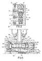
- Figure 3 is a cross-section of the swash-plate pump through a cylinder thereof fitted with a diverter valve as shown incorporated in the system of Figure 1;
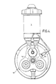
- Figure 4 is an end view of the pump shown in Figure 3;
- Figure 5 is detail cross-section of the swash-plate pump shown in Figure 3 but taken through one of the other cylinders.
- The system shown in Figure 1 includes a constant flow circuit including a steering unit and
valve 14, and having constant flow delivery CFD and constant flow return CFR lines connected for the supply thereto of hydraulic fluid to a three- cylinder swash-plate pump 12 having adrive shaft 10 andoil reservoir 16. A constant pressure circuit controllingvehicle brakes 18 via a full powerhydraulic brake valve 20 includes ahydraulic accumulator 22 which is supplied with fluid under pressure by the same swash-plate pump 12 via adiverter valve 24. Downstream of anon-return valve 26 in the constant pressure delivery line CPD and upstream of theaccumulator 20 is a branched connection togovernor valve 28 having both constant pressure return line CPR and a signal line S to thediverter valve 24. The brake valve return line BVR is in common with the constant flow return line CFR. - As shown in Figure 2, the
governor valve 28 has a supply port 30 (in communication with the delivery line CPD) a return port 32 (to which the return line CPR is connected) and a signal ortrigger port 34. Within thegovernor valve bore 36 aresleeves pin upper pin 42 is biased downwardly by aspring 46 acting on apressure plate 48 with a force which is adjustable by varying the position of ascrewed plug 50 in a threaded upper end of thebore 36. Theplug 50 is retained against movement due to spurious vibration etc., by alocking strip 52 clamped by ascrew 54. - When the accumulator is fully charged, the pressure at the
supply port 30 is sufficient to raise thelower pin 44 so lifting theball 56 from its seat on thelower sleeve 38 into contact with the seat on theupper sleeve 40 against the action of thespring 46. In this state, oil leaks through the clearance between thepin 44 and the sleeve 38 (at the same time creating sufficient drag force on the pin to resist the spring) to generate a high pressure signal at thesignal port 34 connected to thediverter valve 24. Should the accumulator pressure fall below this level, thepin 42 is pressed down by thespring 46 onto its seat on the lower sleeve, so shutting off thesupply port 30 and establishing a flowpath through thesleeve 40, drillings 58 andspring chamber 60 to thereturn port 32, whereby the pressure signal is removed. This causes thediverter valve 24 to supply fluid under pressure as described below until the desired pressure is reached, at which point thepin 44 is once again lifted to transmit a pressure signal to thediverter valve 24. - The governor cut-out pressure is typically 2500 psi (17237 KN/m2) but is adjustable by means of the screwed plug - and the cut-in (i.e. the point at which a pressure signal is transmitted to the diverter valve) pressure may be about 150 psi (1034 KN/m2) below the cut-out pressure.
- Referring now to Figures 3 to 5, the swash-
plate pump 12 has arotatable drive shaft 110 to which is keyed a swash-plate 102 in sliding contact with apiston return plate 108 and threepistons 129, each working within acylindrical sleeve 128 and connected to thereturn plate 108 by atrunnion 105 seated in acup 106 forming a universal type ball and socket joint. Thereturn plate 108 is mounted upon the part spherical end of ahollow plunger 109 which end is urged into engagement with a complementary central seat in the return plate by aspring 115. As thedrive shaft 110, which passes through thehollow plunger 109, rotates relative thereto the inclined working face of theswash plate 102 slides over the rear face of thereturn plate 108 so causing the return plate to pivot or wobble back and forth on the part spherical end of the spring-loadedplunger 109 so displacing eachpiston 129 in turn through a working and return stroke within the associatedcylinder sleeve 128. - Each of the
cylindrical sleeves 128 is fitted, together with associated seals, in a bore in thepump body 101. All of these bores contain a square plate-valve 131 urged against a valve seat defined by the end of thesleeve 128 by aspring 139. Two of the said bores are closed by a plug 113 (see Figures 4 and 5) havingdrillings 132 communicating viaother drillings 134 in thebody 101, with the constant flow delivery port incorporating aflow control valve 136 to which the delivery line CFD is connected. In the case of these two bores, thespring 139 is received within aspring guide 127 which hasradial ports 137 and an axial port 138 communicating via the said drillings with the constant flow delivery port CFD. - The
diverter valve 24 is fitted in and closes the third bore of the pump. As will be seen from Figure 3 this includes anoutlet pipe 160 for connection to the delivery line CPD and carries asleeve 162 which is slidable within the annular gap between theoutlet pipe 160 and thediverter valve housing 164, when a pressure signal appears on the signal line S, to uncover radial drillings in thepipe 160 so diverting the fluid discharged from the associated cylinder to the constant flow circuit via thedrillings 134 in thepump housing 101. - The areas within the
diverter valve 24 are such that should thegovernor valve 28 fail, the pumping pressure lifts the diverter valve admitting fluid to the constant flow circuit so that a separate safety valve is not required for the constant pressure brake circuit. - The
oil reservoir 16 mounted on thepump body 101 communicates with the interior of thecylindrical sleeve 128 in the bore fitted with thediverter valve 24, via anannular chamber 190 andradial drillings 192 in the sleeve itself. Thechamber 190 also communicates viadrillings 194 with similar annular chambers surrounding the other twocylindrical sleeves 128 and with the constant flow return viadrillings 196 and anannular chamber 198 surrounding theoutlet pipe 180. - Within the
outlet pipe 180 is a flow control valve comprising abush 136 having a restricted central orifice and biased toward a position wherein thebush 136 engages aseat 156 closing-off aflowpath 157 communicating with the constant flow circuit return. Thus when the delivery viadrillings 134 to the interior of theoutlet pipe 160 exceeds a predetermined flow determined by the strength ofspring 158, the bush unseats so diverting fluid directly to the constant flow return and thence to thereservoir 16. - The
outlet pipe 180 also incorporates a pilot operatedpressure relief valve 200 open to the pressure of fluid delivery in the chamber preceding theflow control valve 136 via a restrictedorifice 202. When the pressure within achamber 204 exceeds a predetermined value (typically 2500 psi (17237 KN/m2)) aball valve 206 is lifted from its seat in opposition to aball leading spring 208 so establishing communication with the constant flow return until the delivery pressure falls to below the said predetermined value. - The flow control valve and pilot operated pressure relief are fitted to safeguard the constant flow steering circuit. Additionally, the pump inlet ports are arranged to give flow starvation when the pump is at very high speeds such as engine over-run.
Claims (4)
Applications Claiming Priority (4)
| Application Number | Priority Date | Filing Date | Title |
|---|---|---|---|
| GB8115004 | 1981-05-15 | ||
| GB8115004 | 1981-05-15 | ||
| GB8119376 | 1981-06-23 | ||
| GB8119376 | 1981-06-23 |
Publications (3)
| Publication Number | Publication Date |
|---|---|
| EP0066398A2 EP0066398A2 (en) | 1982-12-08 |
| EP0066398A3 EP0066398A3 (en) | 1983-10-12 |
| EP0066398B1 true EP0066398B1 (en) | 1986-05-28 |
Family
ID=26279482
Family Applications (1)
| Application Number | Title | Priority Date | Filing Date |
|---|---|---|---|
| EP82302479A Expired EP0066398B1 (en) | 1981-05-15 | 1982-05-14 | Hydraulic control systems |
Country Status (2)
| Country | Link |
|---|---|
| EP (1) | EP0066398B1 (en) |
| DE (1) | DE3271342D1 (en) |
Families Citing this family (3)
| Publication number | Priority date | Publication date | Assignee | Title |
|---|---|---|---|---|
| DE3447366A1 (en) * | 1984-12-24 | 1986-07-03 | Linde Ag, 6200 Wiesbaden | CONTROL DEVICE FOR A HYDROSTATIC GEARBOX |
| CN102837735B (en) * | 2012-07-27 | 2014-02-05 | 浙江万安科技股份有限公司 | Car chassis hydraulic active control system |
| CN114715266B (en) * | 2022-03-31 | 2023-06-20 | 湖南三一华源机械有限公司 | Steering brake assembly, control method and control device thereof and engineering vehicle |
Citations (1)
| Publication number | Priority date | Publication date | Assignee | Title |
|---|---|---|---|---|
| US2984186A (en) * | 1957-07-11 | 1961-05-16 | Thompson Ramo Wooldridge Inc | Multiple pump unit |
Family Cites Families (5)
| Publication number | Priority date | Publication date | Assignee | Title |
|---|---|---|---|---|
| US2799996A (en) * | 1954-06-07 | 1957-07-23 | Vickers Inc | Single pump, plural motor power transmission |
| US2850878A (en) * | 1956-03-23 | 1958-09-09 | Thompson Prod Inc | Power steering and accessory system |
| GB1506850A (en) * | 1974-08-13 | 1978-04-12 | Cam Gears Ltd | Hydraulic systems |
| DE3101907A1 (en) * | 1981-01-22 | 1982-08-19 | Alfred Teves Gmbh, 6000 Frankfurt | Accumulator-loading valve |
| FR2984186B1 (en) * | 2011-12-16 | 2013-12-20 | Scl Internat Special Coating Lab | SEMI-AUTOMATIC GLASSES TREATMENT MACHINE |
-
1982
- 1982-05-14 EP EP82302479A patent/EP0066398B1/en not_active Expired
- 1982-05-14 DE DE8282302479T patent/DE3271342D1/en not_active Expired
Patent Citations (1)
| Publication number | Priority date | Publication date | Assignee | Title |
|---|---|---|---|---|
| US2984186A (en) * | 1957-07-11 | 1961-05-16 | Thompson Ramo Wooldridge Inc | Multiple pump unit |
Also Published As
| Publication number | Publication date |
|---|---|
| DE3271342D1 (en) | 1986-07-03 |
| EP0066398A3 (en) | 1983-10-12 |
| EP0066398A2 (en) | 1982-12-08 |
Similar Documents
| Publication | Publication Date | Title |
|---|---|---|
| US3768928A (en) | Pump control system | |
| US5603609A (en) | Variable delivery swash plate pump having a piston located spill port | |
| GB2104250A (en) | An electrohydraulic adjusting device for an hydrostatic machine | |
| GB2090915A (en) | Pumping apparatus | |
| CA1197276A (en) | Auxiliary release device for a hydraulic pressure releasable brake | |
| US3982855A (en) | Radial piston pump | |
| US3221660A (en) | Automatic control for variable displacement pump | |
| US4831826A (en) | Hydraulic brake system | |
| US6634173B2 (en) | Hydraulic rescue system | |
| US4034564A (en) | Piston pump assembly having load responsive controls | |
| SE429032B (en) | MOTOR VEHICLE STEERING DEVICE | |
| JPS6157474B2 (en) | ||
| US3350881A (en) | Constant delivery pump system | |
| US5201174A (en) | Auxiliary hydraulic pump system | |
| EP0066398A2 (en) | Hydraulic control systems | |
| US4007593A (en) | Motor vehicle open center series hydraulic circuit | |
| GB1470319A (en) | Hydraulic pump and valve unit | |
| US4013380A (en) | Control systems for variable capacity hydraulic machines | |
| US2643613A (en) | Hydraulic pump | |
| US6109385A (en) | Hydrostatic unit for driving an industrial truck | |
| US5482442A (en) | Hydraulic radial piston machines | |
| US4930994A (en) | Radial piston pump | |
| US3696613A (en) | Hydraulic steering system having auxiliary power source | |
| JPH05213212A (en) | Brake valve used for load sensing hydraulic device | |
| EP0280532A2 (en) | Power transfer apparatus |
Legal Events
| Date | Code | Title | Description |
|---|---|---|---|
| PUAI | Public reference made under article 153(3) epc to a published international application that has entered the european phase |
Free format text: ORIGINAL CODE: 0009012 |
|
| AK | Designated contracting states |
Designated state(s): DE FR GB IT SE |
|
| PUAL | Search report despatched |
Free format text: ORIGINAL CODE: 0009013 |
|
| AK | Designated contracting states |
Designated state(s): DE FR GB IT SE |
|
| 17P | Request for examination filed |
Effective date: 19830921 |
|
| GRAA | (expected) grant |
Free format text: ORIGINAL CODE: 0009210 |
|
| AK | Designated contracting states |
Kind code of ref document: B1 Designated state(s): DE FR GB IT SE |
|
| REF | Corresponds to: |
Ref document number: 3271342 Country of ref document: DE Date of ref document: 19860703 |
|
| ET | Fr: translation filed | ||
| ITF | It: translation for a ep patent filed | ||
| PLBE | No opposition filed within time limit |
Free format text: ORIGINAL CODE: 0009261 |
|
| STAA | Information on the status of an ep patent application or granted ep patent |
Free format text: STATUS: NO OPPOSITION FILED WITHIN TIME LIMIT |
|
| 26N | No opposition filed | ||
| ITTA | It: last paid annual fee | ||
| PGFP | Annual fee paid to national office [announced via postgrant information from national office to epo] |
Ref country code: GB Payment date: 19920403 Year of fee payment: 11 |
|
| PGFP | Annual fee paid to national office [announced via postgrant information from national office to epo] |
Ref country code: SE Payment date: 19920428 Year of fee payment: 11 |
|
| PGFP | Annual fee paid to national office [announced via postgrant information from national office to epo] |
Ref country code: FR Payment date: 19920430 Year of fee payment: 11 |
|
| PGFP | Annual fee paid to national office [announced via postgrant information from national office to epo] |
Ref country code: DE Payment date: 19920729 Year of fee payment: 11 |
|
| PG25 | Lapsed in a contracting state [announced via postgrant information from national office to epo] |
Ref country code: GB Effective date: 19930514 |
|
| PG25 | Lapsed in a contracting state [announced via postgrant information from national office to epo] |
Ref country code: SE Effective date: 19930515 |
|
| GBPC | Gb: european patent ceased through non-payment of renewal fee |
Effective date: 19930514 |
|
| PG25 | Lapsed in a contracting state [announced via postgrant information from national office to epo] |
Ref country code: FR Effective date: 19940131 |
|
| PG25 | Lapsed in a contracting state [announced via postgrant information from national office to epo] |
Ref country code: DE Effective date: 19940201 |
|
| REG | Reference to a national code |
Ref country code: FR Ref legal event code: ST |
|
| EUG | Se: european patent has lapsed |
Ref document number: 82302479.9 Effective date: 19931210 |