EP0065802A1 - Device for packing a fowl - Google Patents
Device for packing a fowl Download PDFInfo
- Publication number
- EP0065802A1 EP0065802A1 EP82200584A EP82200584A EP0065802A1 EP 0065802 A1 EP0065802 A1 EP 0065802A1 EP 82200584 A EP82200584 A EP 82200584A EP 82200584 A EP82200584 A EP 82200584A EP 0065802 A1 EP0065802 A1 EP 0065802A1
- Authority
- EP
- European Patent Office
- Prior art keywords
- pushing
- fowl
- bag
- legs
- members
- Prior art date
- Legal status (The legal status is an assumption and is not a legal conclusion. Google has not performed a legal analysis and makes no representation as to the accuracy of the status listed.)
- Granted
Links
- 238000012856 packing Methods 0.000 title claims abstract description 6
- 244000144977 poultry Species 0.000 abstract 1
- 241000272194 Ciconiiformes Species 0.000 description 2
- 238000010276 construction Methods 0.000 description 2
- 241000287828 Gallus gallus Species 0.000 description 1
- 230000004913 activation Effects 0.000 description 1
- 238000007664 blowing Methods 0.000 description 1
- 210000000988 bone and bone Anatomy 0.000 description 1
- 235000013330 chicken meat Nutrition 0.000 description 1
- 230000000694 effects Effects 0.000 description 1
- 230000000717 retained effect Effects 0.000 description 1
- 239000007787 solid Substances 0.000 description 1
- 208000005123 swayback Diseases 0.000 description 1
- 230000001360 synchronised effect Effects 0.000 description 1
- 230000003245 working effect Effects 0.000 description 1
Images


Classifications
-
- B—PERFORMING OPERATIONS; TRANSPORTING
- B65—CONVEYING; PACKING; STORING; HANDLING THIN OR FILAMENTARY MATERIAL
- B65B—MACHINES, APPARATUS OR DEVICES FOR, OR METHODS OF, PACKAGING ARTICLES OR MATERIALS; UNPACKING
- B65B5/00—Packaging individual articles in containers or receptacles, e.g. bags, sacks, boxes, cartons, cans, jars
- B65B5/04—Packaging single articles
- B65B5/045—Packaging single articles in bags
-
- B—PERFORMING OPERATIONS; TRANSPORTING
- B65—CONVEYING; PACKING; STORING; HANDLING THIN OR FILAMENTARY MATERIAL
- B65B—MACHINES, APPARATUS OR DEVICES FOR, OR METHODS OF, PACKAGING ARTICLES OR MATERIALS; UNPACKING
- B65B25/00—Packaging other articles presenting special problems
- B65B25/06—Packaging slices or specially-shaped pieces of meat, cheese, or other plastic or tacky products
- B65B25/064—Packaging slices or specially-shaped pieces of meat, cheese, or other plastic or tacky products of poultry
Definitions
- the invention relates to a device for packing a fowl, provided with a dressing passage and one or more pushing members for pushing the fowl through said pressing passage, : one of which is adapted to engage the ends of the legs and to push them against the body.
- the invention aims to counter as far as possible irregularities to occur when pushing the fowl, specially its legs. Specifically the case may occur that the fowl twists more or less when being pushed, which may cause it to take an oblique or wrong position,so that further packing becomes difficult and even a packing machine may be disordered or has to be switched off.
- the invention aims to provide in a simple way that the fowl, when its legs are pushed, will be pushed straight forward into the bag with a considerably higher certainty.
- a central baffle is present at both sides of which the said pushing member adapted to push the ends of the legs is active.
- the right position of the legs obtained with the invention can be taken advantage of by providing that the front side of the further pushing member is located at a distance from the lower side of the said dressing passage.
- the further pushing member will generally push the upper parts of the legs as well as the body of the fowl and do this relatively straight on, so that by reason of the further determination of the location of the ends of the legs practically no disturbancy has to be considered.
- the further pushing member has a pushing surface oriented transverse to the direction of movement of the pushing member and located at some distance behind its front side. This pushing surface will evenly shift forward the body of the fowl below the upper parts of the legs, wherewith also advantage is taken of the fact that the legs with their ends are received at a relatively high level, so that space for the driving element is available.
- the central baffle is mounted to a support surface for the legs and perpendicular to said surface.
- a support surface on which the legs can simply be laid down has already with a simple straight front edge a sufficient holding capability for the fowl and the upper part of the legs, whereas there below sufficient space is available for the pushing surface.
- said one ' pushing member is provided with a slit for receiving the central baffle.
- FIG. 1 indicates a deposit gutter having slightly converging vertical walls 2 and centrally below its bottom a bottom plate 3 movable in its longitudinal direction.
- a driving member 4 which is for instance a pneumatical cylinder and has not further been detailed in the drawing.
- a driving member 5 that is executed in triple serves to actuate stretch members 7.
- Each stretch member 7 is formed by a pivotable sheet having a pivot shaft 6 and is pivotable from the position shown in fig. 1 and 2 into the position shown in fig. 3, in which each of them clamps a bag 9 between itself and a fixedly mounted counter member 8.
- the bag 9 is the uppermost of a stack 10 of bags which by means of pressurized air from a nozzle 11 is brought in the shown position and therein fixed by the stretching members 7.
- the pushing member 12 which are movable in the longitudinal direction of the bag become active which can be carried out pneumatically, wherewith the member 12 presses against the body of the fowl.
- the pushing member 12 consists of a horizontal plate with at its lower side somewhat retracted a transverse sheet 25 and at its upper side in the middle a vertical baffle 26 extending in the longitudinal direction.
- the member 13 has at its front side two recesses 14, by reason of which this member 13 is adapted to push the legs of the fowl and to lay them against the body of the fowl.
- a slit 27 in the member 13 enables to accomodate the baffle 26.
- a further advantage of the shown construction is,that the wind blowing from the nozzle 11 can bring a bag of the stack of bags in the position desired for stretching , wherewith this happens at the moment that the turntable 17 is in the position shown in fig. 1 with interrupted lines, so that the advantage is obtained that the bag is not hampered by the turntable when bringing the bag in the desired position, after which, when the turntable is in the position shown in solid lines in fig. 1, it can serve the purpose of supporting the bag and the fowl, when the bottom plate has been retracted therefrom.
- brackets 16 and 16' are actuated because they are via rotating shafts 21 connected to actuating arms 22 with at their ends follow rollers 23' and 23 cooperating with said cam 24.
- Tension springs 29 keep the follow rollers 23 and 23' in engagement with the cam 24.
- the follow rollers 23 and 23' and the cam 24 have been shown again in fig. 7. Therewith the cam has been shown in the position of fig. 3 of the drawing. This cam has a non shown control member which can cause it to rotate. With a first rotational movement the cam moves 30° counter clockwise by reason of which follow roller 23 sways inwardly over the cam part a1, so that bracket 16' (see fig. 2) moves from the position of fig. 3 into that of fig. 4.
- follow roller 23' runs over cam part b1 of cam 2 4 and consequently the related bracket 16 is not swayed.
- the mutual position of the cam and follow rollers is maintained until the position of fig. 5 is reached, thus the fowl being completely shifted forward and the bottom plate 3 retracted, wherewith the stretching members 7 are still kept in their opened position by the pushing member 13.
- the cam 24 is rotated 60° further counter clockwise.
- the follow roller 23 cooperates with the part a2 of the cam 24, wherewith no variation in radius occurs and consequently no swaying movement of the related bracket.
- the follow roller 23' runs over cam part b2 which means an increase of radius, so that the corresponding bracket 16 is swayed downward.
- a fowl needs not to happen with special care, provided the ends of the legs are located at both sides of the baffle 26 on the horizontal plate of the pushing member 12 and th;: fowl further is located such, that its brest- bone comes between the guide ribs 28.
- the pushing members 12 and 13 are shifted toward the left, wherewith initially they move equally but the pushing member 13 receives at the end of its stroke a higher velocity and overtakes the pushing member 12 until the position of fig. 4 is attained, in which the front edges of the pushing members 12 and 13 almost coincide.
- the front edge of 12 is located on a certain height, in practice some cm above the deposit gutter, this edge engages the back side of the upper parts of the legs and the body of the fowl. This causes in combination with the baffle 26 the fowl to be pushed straight forward, which cause is also enhanced by the vertical sheet 25.
- the final position of the pushing members 12 and 13 has to .be such, that a good dressing of the bird is obtained, wherewith for chickens it generally is preferred that the ends of the legs are located near the front edge of the pushing member 12. This may, however, be different for other types of fowl.
- the cam 24 When starting the device the cam 24 is rotated 30° counter clockwise, by reason of which the retaining member 16' sways upwardly into the position of fig. 4. After attaining the position of fig. 4 the actuating members 5 are retracted and the stretching members 7 can sway back, wherewith, however, the pushing members 12 and 13 prevent that they sway already completely back into the position of fig. 1 and 2.
- the device is in the position of fig. 1 and 2, but with a rotation of the turntable over 180°. Now the next fowl can be deposed into the deposit gutter and after activation of the actuating mechanism the whole cycle will be repeated.
Landscapes
- Engineering & Computer Science (AREA)
- Mechanical Engineering (AREA)
- Fodder In General (AREA)
- Container Filling Or Packaging Operations (AREA)
- Springs (AREA)
- Processing Of Meat And Fish (AREA)
- Containers And Plastic Fillers For Packaging (AREA)
- Catching Or Destruction (AREA)
- Packging For Living Organisms, Food Or Medicinal Products That Are Sensitive To Environmental Conditiond (AREA)
Abstract
Description
- The invention relates to a device for packing a fowl, provided with a dressing passage and one or more pushing members for pushing the fowl through said pressing passage, : one of which is adapted to engage the ends of the legs and to push them against the body.
- Such a device is known from the Dutch Patent Application 7702628 (Stork).
- The invention aims to counter as far as possible irregularities to occur when pushing the fowl, specially its legs. Specifically the case may occur that the fowl twists more or less when being pushed, which may cause it to take an oblique or wrong position,so that further packing becomes difficult and even a packing machine may be disordered or has to be switched off.
- The invention aims to provide in a simple way that the fowl, when its legs are pushed, will be pushed straight forward into the bag with a considerably higher certainty.
- Accordingly it is provided according to the invention, that a central baffle is present at both sides of which the said pushing member adapted to push the ends of the legs is active.
- When applying the invention in case a further pushing member is present, as per se is known from the cited Dutch Patent Application 7702628 (Stork) it is advantageously provided that the baffle is part of this further pushing member for pushing the fowl into the bag.
- Therewith the right position of the legs obtained with the invention can be taken advantage of by providing that the front side of the further pushing member is located at a distance from the lower side of the said dressing passage. By this feature the further pushing member will generally push the upper parts of the legs as well as the body of the fowl and do this relatively straight on, so that by reason of the further determination of the location of the ends of the legs practically no disturbancy has to be considered.
- Specially it can be provided therewith that the further pushing member has a pushing surface oriented transverse to the direction of movement of the pushing member and located at some distance behind its front side. This pushing surface will evenly shift forward the body of the fowl below the upper parts of the legs, wherewith also advantage is taken of the fact that the legs with their ends are received at a relatively high level, so that space for the driving element is available.
- Accordingly it is preferably provided that the central baffle is mounted to a support surface for the legs and perpendicular to said surface. Such a support surface, on which the legs can simply be laid down has already with a simple straight front edge a sufficient holding capability for the fowl and the upper part of the legs, whereas there below sufficient space is available for the pushing surface.
- When applying the invention it is preferably provided that said one' pushing member is provided with a slit for receiving the central baffle.
- In the following the invention is further elucidated on hand of the drawing, in which:
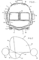
- Figure 1 shows a plan view of the invention in the starting position;
- Figure 2 is a side view of the invention in the starting position;
- Figure 3 corresponds to fig. 2 but shows a further stage;
- Figure 4 shows a still further stage in the same manner as fig. 2 and 3;
- Figure 5 shows a still further stage;
- Figure 6 schematically shows a cross-section over the line VI-VI of fig..4;
- Figure 7 serves to elucidate a control cam; and
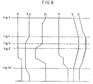
- Figure 8 shows a number of graphs in which the workings of several parts of the invention are shown in mutual correlation.
- In the
drawing reference 1 indicates a deposit gutter having slightly convergingvertical walls 2 and centrally below its bottom abottom plate 3 movable in its longitudinal direction. As more specifically and schematically has been shown in fig. 2-5 inclusive thebottom plate 3 can be moved by a driving member 4, which is for instance a pneumatical cylinder and has not further been detailed in the drawing. - In fig. 6 the cross-sectional shape of the
deposit gutter 1 and thebottom plate 3 as well as a guide 3' in which thebottom plate 3 is guided, are shown. - A
driving member 5 that is executed in triple serves to actuatestretch members 7. Eachstretch member 7 is formed by a pivotable sheet having apivot shaft 6 and is pivotable from the position shown in fig. 1 and 2 into the position shown in fig. 3, in which each of them clamps abag 9 between itself and a fixedly mountedcounter member 8. - The
bag 9 is the uppermost of astack 10 of bags which by means of pressurized air from anozzle 11 is brought in the shown position and therein fixed by thestretching members 7. - Synchronous with the actuation of the driving
members 5 for the stretchingmembers 7 also the driving member 4 for thebottom plate 3 has executed its activity, so that thebottom plate 3 has taken the position shown in fig. 3. - Following to this the pushing
members member 12 presses against the body of the fowl. The pushingmember 12 consists of a horizontal plate with at its lower side somewhat retracted atransverse sheet 25 and at its upper side in the middle avertical baffle 26 extending in the longitudinal direction. Themember 13 has at its front side tworecesses 14, by reason of which thismember 13 is adapted to push the legs of the fowl and to lay them against the body of the fowl. Aslit 27 in themember 13 enables to accomodate thebaffle 26. - As more specifically appears from fig. 4 the
members abutment member 15. Therewith thebottom plate 3 is following to this retracted, so that the position of fig. 5 comes to existence. In this position a retainingmember 16 is pr-ssed on the fowl, as has been show in interrupted lines in fig. 5, the fowl being supported by aturntable 17. After this theturntable 17 is rotated until the bag with the fowl is in the position indicated withreference 18 in which position the bag is closed with aclosing device 19 that has not further been detailed. - An important advantage of this construction is, that the time necessary for stretching and filling of a bag forms a first cycle and the time necessary for closing the bag a second one, which increases the working speed of the complete device in a considerable extend.
- A further advantage of the shown construction is,that the wind blowing from the
nozzle 11 can bring a bag of the stack of bags in the position desired for stretching , wherewith this happens at the moment that theturntable 17 is in the position shown in fig. 1 with interrupted lines, so that the advantage is obtained that the bag is not hampered by the turntable when bringing the bag in the desired position, after which, when the turntable is in the position shown in solid lines in fig. 1, it can serve the purpose of supporting the bag and the fowl, when the bottom plate has been retracted therefrom. - In fig. 6 a cross-section through the
bottom plate 3 has been shown, wherewith it is visible that between this plate and thebag 9 two passage gutters 20 for air are present at the lower side. This means that when the fowl is shifted over the bottom plate into the bag the air from the front side of the bag can always easily be vented through the gutters 20, whereas nevertheless, after theplate 3 has been retracted, a good tight enclosure of the bag around the fowl can be realized. The stretching members7 are also schematically shown in fig. 6 as well ar= thecounter members 8 and the pushingmembers uppermost stretch member 7 at its inner side has guidingribs 28. - By rotating a control cam 4 the
brackets 16 and 16' are actuated because they are via rotatingshafts 21 connected to actuatingarms 22 with at their ends followrollers 23' and 23 cooperating with saidcam 24. Tension springs 29 keep thefollow rollers 23 and 23' in engagement with thecam 24. - The
follow rollers 23 and 23' and thecam 24 have been shown again in fig. 7. Therewith the cam has been shown in the position of fig. 3 of the drawing. This cam has a non shown control member which can cause it to rotate. With a first rotational movement the cam moves 30° counter clockwise by reason of which followroller 23 sways inwardly over the cam part a1, so that bracket 16' (see fig. 2) moves from the position of fig. 3 into that of fig. 4. - Therewith follow roller 23' runs over cam part b1 of
cam 24 and consequently therelated bracket 16 is not swayed. The mutual position of the cam and follow rollers is maintained until the position of fig. 5 is reached, thus the fowl being completely shifted forward and thebottom plate 3 retracted, wherewith the stretchingmembers 7 are still kept in their opened position by the pushingmember 13. Now thecam 24 is rotated 60° further counter clockwise. Then thefollow roller 23 cooperates with the part a2 of thecam 24, wherewith no variation in radius occurs and consequently no swaying movement of the related bracket. The follow roller 23' runs over cam part b2 which means an increase of radius, so that thecorresponding bracket 16 is swayed downward. Now theturntable 17 is rotated over 90°, wherewith the follow roller 23' runs over cam part b3 and followroller 23 over cam part a3. None of these cam parts show a variation of radius, so that no swaying movement occurs. After this the cam is rotated 90° clockwise, by reason of which followroller 23 runs over cam part a3 but now in opposite direction, and follow roller 23' over cam part b3, also in opposite direction. Following to this the table rotates still 90° further, so that the starting position is taken again, but with exchange of the brackets and followrollers - The working of the device in the following is further elucidated on hand of the time graphs of fig. 8. In this figure the vertical axis is the time axis, wherewith as reference the positions of the several figures are indicated and the graphs are indicated with the references of the parts to which these graphs relate. These are the
nozzle 11; actuatingmembers 5 and 4 which are always actuated together; thecam 24; theturntable 17 and the pushingmembers - In fig. 8 is started from the position of fig. 3, because in that position deposing of a fowl in the
deposit gutter 1 occurs. After this an actuating mechanism is activated by reason of which a complete cycle is carried out until the position of fig. 3 is reached again. - Deposing a fowl needs not to happen with special care, provided the ends of the legs are located at both sides of the
baffle 26 on the horizontal plate of the pushingmember 12 and th;: fowl further is located such, that its brest- bone comes between theguide ribs 28. - After starting the device the pushing
members member 13 receives at the end of its stroke a higher velocity and overtakes the pushingmember 12 until the position of fig. 4 is attained, in which the front edges of the pushingmembers - Because the front edge of 12 is located on a certain height, in practice some cm above the deposit gutter, this edge engages the back side of the upper parts of the legs and the body of the fowl. This causes in combination with the
baffle 26 the fowl to be pushed straight forward, which cause is also enhanced by thevertical sheet 25. - The final position of the pushing
members member 12. This may, however, be different for other types of fowl. - When starting the device the
cam 24 is rotated 30° counter clockwise, by reason of which the retaining member 16' sways upwardly into the position of fig. 4. After attaining the position of fig. 4 theactuating members 5 are retracted and the stretchingmembers 7 can sway back, wherewith, however, the pushingmembers - In the same time the driving member 4 and consequently the
bottom plate 3 are retracted, by reason of which some room in the bag is created and the pushingmembers lines - Starting from the position of fig. 5 the
cam 24 is rotated 60° counter clockwise, so that the retainingmember 16 takes the position indicated with interrupted lines. The end of this movement is in fig. 8 indicated with fig. 5'. Now the retracting of the pushingmembers members line 17 in fig. 8. Therewith the precedingbag 18, which has been closed by a not furtherdetailed closing device 19, engages an abutment and wipe offmember 30 and falls from the table 17. With this rotational movement of the table 17 thebag 9 is retained bybracket 16. After this rotational movement over 90°, wherewith the bag is tired away from thebag stack 10, as is known per se, thenozzle 11 becomes active. After this the next bag of thestack 10, is brought in the position of thebag 9 in fig. 1 and 2, wherewith the table 17 rotated over a quarter of a revolution does not hinder the bag. - After the first movement of the
turntable 17 thecam 24 rotates 90° clockwise,vide graph 24. This does not cause any positional change of the retainingmembers 16 and 16'. - Following to this the
turntable 17 rotates again 90°, wherewith as has been elucidated earlier on hand of fig. 7 again no positional change of the retainingmembers 16 and 16' occurs. In the mean time the pushingmembers - Now the device is in the position of fig. 1 and 2, but with a rotation of the turntable over 180°. Now the next fowl can be deposed into the deposit gutter and after activation of the actuating mechanism the whole cycle will be repeated.
Claims (8)
Priority Applications (1)
| Application Number | Priority Date | Filing Date | Title |
|---|---|---|---|
| AT82200584T ATE11512T1 (en) | 1981-05-14 | 1982-05-12 | DEVICE FOR PACKING POULTRY. |
Applications Claiming Priority (2)
| Application Number | Priority Date | Filing Date | Title |
|---|---|---|---|
| NL8102374A NL8102374A (en) | 1981-05-14 | 1981-05-14 | DEVICE FOR PACKING A BIRD. |
| NL8102374 | 1981-05-14 |
Publications (2)
| Publication Number | Publication Date |
|---|---|
| EP0065802A1 true EP0065802A1 (en) | 1982-12-01 |
| EP0065802B1 EP0065802B1 (en) | 1985-01-30 |
Family
ID=19837507
Family Applications (1)
| Application Number | Title | Priority Date | Filing Date |
|---|---|---|---|
| EP82200584A Expired EP0065802B1 (en) | 1981-05-14 | 1982-05-12 | Device for packing a fowl |
Country Status (9)
| Country | Link |
|---|---|
| US (1) | US4464882A (en) |
| EP (1) | EP0065802B1 (en) |
| JP (1) | JPS5820612A (en) |
| AT (1) | ATE11512T1 (en) |
| AU (1) | AU8366782A (en) |
| DE (1) | DE3262117D1 (en) |
| DK (1) | DK212482A (en) |
| ES (1) | ES512170A0 (en) |
| NL (1) | NL8102374A (en) |
Cited By (3)
| Publication number | Priority date | Publication date | Assignee | Title |
|---|---|---|---|---|
| WO1995019293A1 (en) * | 1994-01-18 | 1995-07-20 | Delaware Capital Formation, Inc. | An apparatus for packaging fowl and other products |
| WO2006099488A2 (en) | 2005-03-15 | 2006-09-21 | Poly-Clip System Corp. | Poly-stretch bagger system with hocking pusher |
| CN113353384A (en) * | 2021-06-07 | 2021-09-07 | 常州市金坛志诚机械有限公司 | Continuous baling equipment of cotton bale |
Families Citing this family (13)
| Publication number | Priority date | Publication date | Assignee | Title |
|---|---|---|---|---|
| JPS61273306A (en) * | 1985-05-24 | 1986-12-03 | 日立造船産業株式会社 | Device for inserting vessel to baggy film |
| US5463844A (en) * | 1993-08-18 | 1995-11-07 | W. R. Grace & Co.-Conn. | Machine and method for packaging poultry products |
| US5946888A (en) * | 1998-04-20 | 1999-09-07 | Cryovac, Inc. | Method and apparatus for automatic packaging of cheese |
| CN1606519A (en) * | 2001-12-19 | 2005-04-13 | A·W·A·X·设计研究有限责任公司 | Process and machine for packaging products with stretchable thermoplastic film |
| US20050072118A1 (en) | 2003-10-03 | 2005-04-07 | Griggs Samuel D. | Netting chutes with ribbed flooring for manual and/or automated clipping packaging apparatus |
| US7237369B2 (en) | 2003-10-03 | 2007-07-03 | Tipper Tie, Inc. | Automated clipping packaging systems |
| DE102006013251A1 (en) * | 2006-03-21 | 2007-10-04 | Christian Wolf | Box-like object placing device, has wrapper plug-in area arranged in object conveying direction in freely projecting manner, where free space is provided in wrapper plug-in area for receiving lower side of wrapper |
| DE102007023328A1 (en) * | 2007-05-16 | 2008-11-20 | Anders Agil Gmbh | Warm meat packaging equipment for packing of piece of meat into section of hose, is provided with clamp within area of opening for guidance of hose section of intended hollow body |
| US20130247512A1 (en) * | 2012-03-26 | 2013-09-26 | Eggo Haschke | Automated loader with cone horn |
| US10011380B2 (en) | 2013-08-26 | 2018-07-03 | Tipper Tie, Inc. | Ruckers, reruckers, deruckers and/or skin brakes with stacked gripper layers and related grippers |
| USD729294S1 (en) | 2013-08-26 | 2015-05-12 | Tipper Tie, Inc. | Gripper for automated ruckers, reruckers, deruckers and/or skin brakes |
| BR102016000581B1 (en) * | 2016-01-11 | 2020-06-16 | Camilo Pedro Abati | BIRD PACKING MACHINE |
| WO2023248106A1 (en) * | 2022-06-20 | 2023-12-28 | Sealed Air Nz | Apparatus for packaging of products |
Citations (3)
| Publication number | Priority date | Publication date | Assignee | Title |
|---|---|---|---|---|
| US3254472A (en) * | 1962-02-08 | 1966-06-07 | Union Carbide Corp | Packaging apparatus |
| GB1525559A (en) * | 1974-08-27 | 1978-09-20 | Schur Int As Brdr | Method and apparatus for packing poultry in bags |
| GB1597193A (en) * | 1977-03-10 | 1981-09-03 | Stork Pmt | Packing birds |
Family Cites Families (4)
| Publication number | Priority date | Publication date | Assignee | Title |
|---|---|---|---|---|
| BE788527A (en) * | 1971-09-10 | 1973-01-02 | Moba Bv Apparatenbouw | DEVICE FOR PACKAGING POULTRY |
| US4033088A (en) * | 1975-11-11 | 1977-07-05 | Maschinefabriek Markert B.V. | Method of and apparatus for packaging poultry specimens |
| US4377929A (en) * | 1979-01-24 | 1983-03-29 | W. F. Altenpohl, Inc. | Pre-entry positioning poultry bagging system |
| US4352263A (en) * | 1979-07-26 | 1982-10-05 | Star Packaging Corporation | Method of packaging fowl within stretch bags |
-
1981
- 1981-05-14 NL NL8102374A patent/NL8102374A/en not_active Application Discontinuation
-
1982
- 1982-05-11 US US06/377,046 patent/US4464882A/en not_active Expired - Fee Related
- 1982-05-12 AT AT82200584T patent/ATE11512T1/en not_active IP Right Cessation
- 1982-05-12 DE DE8282200584T patent/DE3262117D1/en not_active Expired
- 1982-05-12 DK DK212482A patent/DK212482A/en not_active Application Discontinuation
- 1982-05-12 EP EP82200584A patent/EP0065802B1/en not_active Expired
- 1982-05-13 ES ES512170A patent/ES512170A0/en active Granted
- 1982-05-13 AU AU83667/82A patent/AU8366782A/en not_active Abandoned
- 1982-05-14 JP JP57081353A patent/JPS5820612A/en active Pending
Patent Citations (3)
| Publication number | Priority date | Publication date | Assignee | Title |
|---|---|---|---|---|
| US3254472A (en) * | 1962-02-08 | 1966-06-07 | Union Carbide Corp | Packaging apparatus |
| GB1525559A (en) * | 1974-08-27 | 1978-09-20 | Schur Int As Brdr | Method and apparatus for packing poultry in bags |
| GB1597193A (en) * | 1977-03-10 | 1981-09-03 | Stork Pmt | Packing birds |
Cited By (6)
| Publication number | Priority date | Publication date | Assignee | Title |
|---|---|---|---|---|
| WO1995019293A1 (en) * | 1994-01-18 | 1995-07-20 | Delaware Capital Formation, Inc. | An apparatus for packaging fowl and other products |
| US5570561A (en) * | 1994-01-18 | 1996-11-05 | Delaware Capital Formation, Inc. | Apparatus for packaging fowl and other products |
| AU676796B2 (en) * | 1994-01-18 | 1997-03-20 | Delaware Capital Formation, Inc. | An apparatus for packaging fowl and other products |
| WO2006099488A2 (en) | 2005-03-15 | 2006-09-21 | Poly-Clip System Corp. | Poly-stretch bagger system with hocking pusher |
| EP1863708A4 (en) * | 2005-03-15 | 2010-01-20 | Poly Clip System Corp | Poly-stretch bagger system with hocking pusher |
| CN113353384A (en) * | 2021-06-07 | 2021-09-07 | 常州市金坛志诚机械有限公司 | Continuous baling equipment of cotton bale |
Also Published As
| Publication number | Publication date |
|---|---|
| NL8102374A (en) | 1982-12-01 |
| ES8304004A1 (en) | 1983-02-16 |
| US4464882A (en) | 1984-08-14 |
| JPS5820612A (en) | 1983-02-07 |
| ATE11512T1 (en) | 1985-02-15 |
| EP0065802B1 (en) | 1985-01-30 |
| ES512170A0 (en) | 1983-02-16 |
| DE3262117D1 (en) | 1985-03-14 |
| DK212482A (en) | 1982-11-15 |
| AU8366782A (en) | 1982-11-18 |
Similar Documents
| Publication | Publication Date | Title |
|---|---|---|
| EP0065802B1 (en) | Device for packing a fowl | |
| RU2054364C1 (en) | Device for putting on sacks for loose products with item-by-item gripping of sacks | |
| US4629446A (en) | Apparatus for erecting folding boxes | |
| EP0014021B1 (en) | Bag closing apparatus | |
| US3939625A (en) | Device for printing and feeding covers to containers | |
| US2761505A (en) | Apparatus for separating connected stacks of sheet material and transporting and turning the separated stacks | |
| NO305742B1 (en) | Device for feeding objects | |
| US7316642B2 (en) | Apparatus for forming containers | |
| US2997833A (en) | Cover opener for cases | |
| GB1572917A (en) | Packaging yarn packages | |
| CN109801437A (en) | A kind of automatic catering appliances | |
| EP1707491B1 (en) | Device for picking and opening boxes suitable for packaging products | |
| EP0065801B1 (en) | Device for packing a fowl in a bag | |
| JPS5813410B2 (en) | Rotary packaging equipment for bag filling | |
| WO1993010968A1 (en) | Apparatus for forming and applying handles to bags | |
| US2349523A (en) | Bottle cap applying device | |
| EP0065341A1 (en) | Apparatus for filling a bag with a fowl | |
| GB2091674A (en) | Blocking devices for conveyors | |
| US4044657A (en) | Case erector | |
| US3556344A (en) | Straw dispenser | |
| US5393180A (en) | Container loading and emptying device for a refuse vehicle and pick up member for the same, and also guides for the pick up member | |
| US2712210A (en) | Machine for closing and sealing cellophane bags | |
| US3533334A (en) | Device for transferring folding boxes to the conveyor of a packaging machine | |
| EP0834395B1 (en) | Parallelepiped carton forming machine | |
| PT1585669E (en) | Machine for filling bags or the like comprising a cam-controlled device |
Legal Events
| Date | Code | Title | Description |
|---|---|---|---|
| PUAI | Public reference made under article 153(3) epc to a published international application that has entered the european phase |
Free format text: ORIGINAL CODE: 0009012 |
|
| AK | Designated contracting states |
Designated state(s): AT BE CH DE FR GB IT LI NL SE |
|
| RAP1 | Party data changed (applicant data changed or rights of an application transferred) |
Owner name: ADMINISTRATIE- EN AUTOMATISERINGSCENTRUM VULCAAN |
|
| 17P | Request for examination filed |
Effective date: 19830125 |
|
| ITF | It: translation for a ep patent filed | ||
| GRAA | (expected) grant |
Free format text: ORIGINAL CODE: 0009210 |
|
| AK | Designated contracting states |
Designated state(s): AT BE CH DE FR GB IT LI NL SE |
|
| PG25 | Lapsed in a contracting state [announced via postgrant information from national office to epo] |
Ref country code: SE Effective date: 19850130 Ref country code: LI Effective date: 19850130 Ref country code: FR Free format text: THE PATENT HAS BEEN ANNULLED BY A DECISION OF A NATIONAL AUTHORITY Effective date: 19850130 Ref country code: CH Effective date: 19850130 Ref country code: BE Effective date: 19850130 Ref country code: AT Effective date: 19850130 |
|
| REF | Corresponds to: |
Ref document number: 11512 Country of ref document: AT Date of ref document: 19850215 Kind code of ref document: T |
|
| REF | Corresponds to: |
Ref document number: 3262117 Country of ref document: DE Date of ref document: 19850314 |
|
| REG | Reference to a national code |
Ref country code: CH Ref legal event code: PL |
|
| PLBI | Opposition filed |
Free format text: ORIGINAL CODE: 0009260 |
|
| 26 | Opposition filed |
Opponent name: HUPKES, HENK Effective date: 19851029 |
|
| NLR1 | Nl: opposition has been filed with the epo |
Opponent name: HUPKES, HENK. |
|
| EN | Fr: translation not filed | ||
| GBPC | Gb: european patent ceased through non-payment of renewal fee | ||
| PLBN | Opposition rejected |
Free format text: ORIGINAL CODE: 0009273 |
|
| STAA | Information on the status of an ep patent application or granted ep patent |
Free format text: STATUS: OPPOSITION REJECTED |
|
| 27O | Opposition rejected |
Effective date: 19870227 |
|
| NLR2 | Nl: decision of opposition | ||
| PG25 | Lapsed in a contracting state [announced via postgrant information from national office to epo] |
Ref country code: GB Effective date: 19881121 |
|
| PG25 | Lapsed in a contracting state [announced via postgrant information from national office to epo] |
Ref country code: DE Effective date: 19890201 |
|
| PGFP | Annual fee paid to national office [announced via postgrant information from national office to epo] |
Ref country code: NL Payment date: 19980531 Year of fee payment: 17 |
|
| PG25 | Lapsed in a contracting state [announced via postgrant information from national office to epo] |
Ref country code: NL Free format text: LAPSE BECAUSE OF NON-PAYMENT OF DUE FEES Effective date: 19991201 |
|
| NLV4 | Nl: lapsed or anulled due to non-payment of the annual fee |
Effective date: 19991201 |