EP0064960B1 - A plant for purifying contaminated air - Google Patents
A plant for purifying contaminated air Download PDFInfo
- Publication number
- EP0064960B1 EP0064960B1 EP19820850089 EP82850089A EP0064960B1 EP 0064960 B1 EP0064960 B1 EP 0064960B1 EP 19820850089 EP19820850089 EP 19820850089 EP 82850089 A EP82850089 A EP 82850089A EP 0064960 B1 EP0064960 B1 EP 0064960B1
- Authority
- EP
- European Patent Office
- Prior art keywords
- liquid
- spray booth
- circulation circuit
- plant
- air
- Prior art date
- Legal status (The legal status is an assumption and is not a legal conclusion. Google has not performed a legal analysis and makes no representation as to the accuracy of the status listed.)
- Expired
Links
- 239000007921 spray Substances 0.000 claims abstract description 65
- 239000007788 liquid Substances 0.000 claims abstract description 47
- 239000000356 contaminant Substances 0.000 claims abstract description 5
- 239000003973 paint Substances 0.000 claims description 35
- 239000010802 sludge Substances 0.000 claims description 26
- 239000002904 solvent Substances 0.000 claims description 21
- 238000007592 spray painting technique Methods 0.000 claims description 10
- 239000002245 particle Substances 0.000 claims description 9
- 238000000746 purification Methods 0.000 claims description 7
- 230000015556 catabolic process Effects 0.000 claims description 6
- 238000006731 degradation reaction Methods 0.000 claims description 6
- 239000000126 substance Substances 0.000 claims description 3
- 239000011230 binding agent Substances 0.000 claims description 2
- 238000011109 contamination Methods 0.000 claims description 2
- 238000005188 flotation Methods 0.000 claims description 2
- 239000000049 pigment Substances 0.000 claims description 2
- 239000007864 aqueous solution Substances 0.000 claims 1
- 239000007900 aqueous suspension Substances 0.000 claims 1
- 238000006065 biodegradation reaction Methods 0.000 abstract description 3
- 238000000926 separation method Methods 0.000 abstract description 3
- 238000004140 cleaning Methods 0.000 abstract 3
- XLYOFNOQVPJJNP-UHFFFAOYSA-N water Substances O XLYOFNOQVPJJNP-UHFFFAOYSA-N 0.000 description 68
- 239000003570 air Substances 0.000 description 41
- 238000009282 microflotation Methods 0.000 description 14
- NBIIXXVUZAFLBC-UHFFFAOYSA-N Phosphoric acid Chemical compound OP(O)(O)=O NBIIXXVUZAFLBC-UHFFFAOYSA-N 0.000 description 8
- 244000005700 microbiome Species 0.000 description 8
- 150000002430 hydrocarbons Chemical class 0.000 description 7
- 235000015097 nutrients Nutrition 0.000 description 7
- IJGRMHOSHXDMSA-UHFFFAOYSA-N Atomic nitrogen Chemical compound N#N IJGRMHOSHXDMSA-UHFFFAOYSA-N 0.000 description 6
- 239000004215 Carbon black (E152) Substances 0.000 description 6
- 229930195733 hydrocarbon Natural products 0.000 description 6
- 239000000463 material Substances 0.000 description 5
- 229910000147 aluminium phosphate Inorganic materials 0.000 description 4
- 230000007423 decrease Effects 0.000 description 4
- 239000000945 filler Substances 0.000 description 4
- 239000004576 sand Substances 0.000 description 4
- 230000006641 stabilisation Effects 0.000 description 4
- 238000011105 stabilization Methods 0.000 description 4
- VHUUQVKOLVNVRT-UHFFFAOYSA-N Ammonium hydroxide Chemical compound [NH4+].[OH-] VHUUQVKOLVNVRT-UHFFFAOYSA-N 0.000 description 3
- OKTJSMMVPCPJKN-UHFFFAOYSA-N Carbon Chemical compound [C] OKTJSMMVPCPJKN-UHFFFAOYSA-N 0.000 description 3
- HEMHJVSKTPXQMS-UHFFFAOYSA-M Sodium hydroxide Chemical compound [OH-].[Na+] HEMHJVSKTPXQMS-UHFFFAOYSA-M 0.000 description 3
- 239000000908 ammonium hydroxide Substances 0.000 description 3
- 230000033228 biological regulation Effects 0.000 description 3
- 229910052757 nitrogen Inorganic materials 0.000 description 3
- 238000010422 painting Methods 0.000 description 3
- 238000004062 sedimentation Methods 0.000 description 3
- 239000007787 solid Substances 0.000 description 3
- QGZKDVFQNNGYKY-UHFFFAOYSA-N Ammonia Chemical compound N QGZKDVFQNNGYKY-UHFFFAOYSA-N 0.000 description 2
- 241000894006 Bacteria Species 0.000 description 2
- OAICVXFJPJFONN-UHFFFAOYSA-N Phosphorus Chemical compound [P] OAICVXFJPJFONN-UHFFFAOYSA-N 0.000 description 2
- 230000001580 bacterial effect Effects 0.000 description 2
- 230000000694 effects Effects 0.000 description 2
- 238000000034 method Methods 0.000 description 2
- 238000012856 packing Methods 0.000 description 2
- 230000008569 process Effects 0.000 description 2
- 238000007790 scraping Methods 0.000 description 2
- 239000010865 sewage Substances 0.000 description 2
- 239000002028 Biomass Substances 0.000 description 1
- QAOWNCQODCNURD-UHFFFAOYSA-N Sulfuric acid Chemical compound OS(O)(=O)=O QAOWNCQODCNURD-UHFFFAOYSA-N 0.000 description 1
- 230000009471 action Effects 0.000 description 1
- 238000004887 air purification Methods 0.000 description 1
- 239000012080 ambient air Substances 0.000 description 1
- 229910021529 ammonia Inorganic materials 0.000 description 1
- 229910052799 carbon Inorganic materials 0.000 description 1
- 230000003247 decreasing effect Effects 0.000 description 1
- 230000029087 digestion Effects 0.000 description 1
- 239000006185 dispersion Substances 0.000 description 1
- 239000003344 environmental pollutant Substances 0.000 description 1
- 238000002474 experimental method Methods 0.000 description 1
- 238000007667 floating Methods 0.000 description 1
- 239000012530 fluid Substances 0.000 description 1
- 239000000383 hazardous chemical Substances 0.000 description 1
- 231100000206 health hazard Toxicity 0.000 description 1
- 238000010438 heat treatment Methods 0.000 description 1
- BHEPBYXIRTUNPN-UHFFFAOYSA-N hydridophosphorus(.) (triplet) Chemical class [PH] BHEPBYXIRTUNPN-UHFFFAOYSA-N 0.000 description 1
- 239000012535 impurity Substances 0.000 description 1
- 238000004519 manufacturing process Methods 0.000 description 1
- 239000011159 matrix material Substances 0.000 description 1
- 230000005012 migration Effects 0.000 description 1
- 238000013508 migration Methods 0.000 description 1
- 238000002156 mixing Methods 0.000 description 1
- 239000000203 mixture Substances 0.000 description 1
- 239000011368 organic material Substances 0.000 description 1
- 238000006213 oxygenation reaction Methods 0.000 description 1
- 238000007591 painting process Methods 0.000 description 1
- 229910052698 phosphorus Inorganic materials 0.000 description 1
- 239000011574 phosphorus Substances 0.000 description 1
- 231100000614 poison Toxicity 0.000 description 1
- 230000007096 poisonous effect Effects 0.000 description 1
- 231100000719 pollutant Toxicity 0.000 description 1
- 238000011084 recovery Methods 0.000 description 1
- 230000009467 reduction Effects 0.000 description 1
- 229920006395 saturated elastomer Polymers 0.000 description 1
- 238000005201 scrubbing Methods 0.000 description 1
- 235000011121 sodium hydroxide Nutrition 0.000 description 1
- 241000894007 species Species 0.000 description 1
- 238000005507 spraying Methods 0.000 description 1
- 229910001220 stainless steel Inorganic materials 0.000 description 1
- 239000010935 stainless steel Substances 0.000 description 1
- 239000001117 sulphuric acid Substances 0.000 description 1
- 235000011149 sulphuric acid Nutrition 0.000 description 1
- 238000009423 ventilation Methods 0.000 description 1
Images




Classifications
-
- C—CHEMISTRY; METALLURGY
- C02—TREATMENT OF WATER, WASTE WATER, SEWAGE, OR SLUDGE
- C02F—TREATMENT OF WATER, WASTE WATER, SEWAGE, OR SLUDGE
- C02F3/00—Biological treatment of water, waste water, or sewage
- C02F3/02—Aerobic processes
- C02F3/12—Activated sludge processes
- C02F3/1205—Particular type of activated sludge processes
- C02F3/1231—Treatments of toxic sewage
-
- B—PERFORMING OPERATIONS; TRANSPORTING
- B01—PHYSICAL OR CHEMICAL PROCESSES OR APPARATUS IN GENERAL
- B01D—SEPARATION
- B01D53/00—Separation of gases or vapours; Recovering vapours of volatile solvents from gases; Chemical or biological purification of waste gases, e.g. engine exhaust gases, smoke, fumes, flue gases, aerosols
- B01D53/14—Separation of gases or vapours; Recovering vapours of volatile solvents from gases; Chemical or biological purification of waste gases, e.g. engine exhaust gases, smoke, fumes, flue gases, aerosols by absorption
-
- B—PERFORMING OPERATIONS; TRANSPORTING
- B01—PHYSICAL OR CHEMICAL PROCESSES OR APPARATUS IN GENERAL
- B01D—SEPARATION
- B01D53/00—Separation of gases or vapours; Recovering vapours of volatile solvents from gases; Chemical or biological purification of waste gases, e.g. engine exhaust gases, smoke, fumes, flue gases, aerosols
- B01D53/14—Separation of gases or vapours; Recovering vapours of volatile solvents from gases; Chemical or biological purification of waste gases, e.g. engine exhaust gases, smoke, fumes, flue gases, aerosols by absorption
- B01D53/1425—Regeneration of liquid absorbents
-
- B—PERFORMING OPERATIONS; TRANSPORTING
- B03—SEPARATION OF SOLID MATERIALS USING LIQUIDS OR USING PNEUMATIC TABLES OR JIGS; MAGNETIC OR ELECTROSTATIC SEPARATION OF SOLID MATERIALS FROM SOLID MATERIALS OR FLUIDS; SEPARATION BY HIGH-VOLTAGE ELECTRIC FIELDS
- B03D—FLOTATION; DIFFERENTIAL SEDIMENTATION
- B03D1/00—Flotation
- B03D1/14—Flotation machines
- B03D1/1412—Flotation machines with baffles, e.g. at the wall for redirecting settling solids
-
- B—PERFORMING OPERATIONS; TRANSPORTING
- B03—SEPARATION OF SOLID MATERIALS USING LIQUIDS OR USING PNEUMATIC TABLES OR JIGS; MAGNETIC OR ELECTROSTATIC SEPARATION OF SOLID MATERIALS FROM SOLID MATERIALS OR FLUIDS; SEPARATION BY HIGH-VOLTAGE ELECTRIC FIELDS
- B03D—FLOTATION; DIFFERENTIAL SEDIMENTATION
- B03D1/00—Flotation
- B03D1/14—Flotation machines
- B03D1/1443—Feed or discharge mechanisms for flotation tanks
- B03D1/1462—Discharge mechanisms for the froth
-
- B—PERFORMING OPERATIONS; TRANSPORTING
- B03—SEPARATION OF SOLID MATERIALS USING LIQUIDS OR USING PNEUMATIC TABLES OR JIGS; MAGNETIC OR ELECTROSTATIC SEPARATION OF SOLID MATERIALS FROM SOLID MATERIALS OR FLUIDS; SEPARATION BY HIGH-VOLTAGE ELECTRIC FIELDS
- B03D—FLOTATION; DIFFERENTIAL SEDIMENTATION
- B03D1/00—Flotation
- B03D1/14—Flotation machines
- B03D1/24—Pneumatic
-
- B—PERFORMING OPERATIONS; TRANSPORTING
- B05—SPRAYING OR ATOMISING IN GENERAL; APPLYING FLUENT MATERIALS TO SURFACES, IN GENERAL
- B05B—SPRAYING APPARATUS; ATOMISING APPARATUS; NOZZLES
- B05B14/00—Arrangements for collecting, re-using or eliminating excess spraying material
- B05B14/40—Arrangements for collecting, re-using or eliminating excess spraying material for use in spray booths
- B05B14/46—Arrangements for collecting, re-using or eliminating excess spraying material for use in spray booths by washing the air charged with excess material
- B05B14/468—Arrangements for collecting, re-using or eliminating excess spraying material for use in spray booths by washing the air charged with excess material with scrubbing means arranged below the booth floor
-
- C—CHEMISTRY; METALLURGY
- C02—TREATMENT OF WATER, WASTE WATER, SEWAGE, OR SLUDGE
- C02F—TREATMENT OF WATER, WASTE WATER, SEWAGE, OR SLUDGE
- C02F3/00—Biological treatment of water, waste water, or sewage
- C02F3/02—Aerobic processes
- C02F3/04—Aerobic processes using trickle filters
-
- B—PERFORMING OPERATIONS; TRANSPORTING
- B05—SPRAYING OR ATOMISING IN GENERAL; APPLYING FLUENT MATERIALS TO SURFACES, IN GENERAL
- B05B—SPRAYING APPARATUS; ATOMISING APPARATUS; NOZZLES
- B05B14/00—Arrangements for collecting, re-using or eliminating excess spraying material
- B05B14/40—Arrangements for collecting, re-using or eliminating excess spraying material for use in spray booths
- B05B14/46—Arrangements for collecting, re-using or eliminating excess spraying material for use in spray booths by washing the air charged with excess material
- B05B14/462—Arrangements for collecting, re-using or eliminating excess spraying material for use in spray booths by washing the air charged with excess material and separating the excess material from the washing liquid, e.g. for recovery
-
- Y—GENERAL TAGGING OF NEW TECHNOLOGICAL DEVELOPMENTS; GENERAL TAGGING OF CROSS-SECTIONAL TECHNOLOGIES SPANNING OVER SEVERAL SECTIONS OF THE IPC; TECHNICAL SUBJECTS COVERED BY FORMER USPC CROSS-REFERENCE ART COLLECTIONS [XRACs] AND DIGESTS
- Y02—TECHNOLOGIES OR APPLICATIONS FOR MITIGATION OR ADAPTATION AGAINST CLIMATE CHANGE
- Y02A—TECHNOLOGIES FOR ADAPTATION TO CLIMATE CHANGE
- Y02A50/00—TECHNOLOGIES FOR ADAPTATION TO CLIMATE CHANGE in human health protection, e.g. against extreme weather
- Y02A50/20—Air quality improvement or preservation, e.g. vehicle emission control or emission reduction by using catalytic converters
-
- Y—GENERAL TAGGING OF NEW TECHNOLOGICAL DEVELOPMENTS; GENERAL TAGGING OF CROSS-SECTIONAL TECHNOLOGIES SPANNING OVER SEVERAL SECTIONS OF THE IPC; TECHNICAL SUBJECTS COVERED BY FORMER USPC CROSS-REFERENCE ART COLLECTIONS [XRACs] AND DIGESTS
- Y02—TECHNOLOGIES OR APPLICATIONS FOR MITIGATION OR ADAPTATION AGAINST CLIMATE CHANGE
- Y02P—CLIMATE CHANGE MITIGATION TECHNOLOGIES IN THE PRODUCTION OR PROCESSING OF GOODS
- Y02P70/00—Climate change mitigation technologies in the production process for final industrial or consumer products
- Y02P70/10—Greenhouse gas [GHG] capture, material saving, heat recovery or other energy efficient measures, e.g. motor control, characterised by manufacturing processes, e.g. for rolling metal or metal working
-
- Y—GENERAL TAGGING OF NEW TECHNOLOGICAL DEVELOPMENTS; GENERAL TAGGING OF CROSS-SECTIONAL TECHNOLOGIES SPANNING OVER SEVERAL SECTIONS OF THE IPC; TECHNICAL SUBJECTS COVERED BY FORMER USPC CROSS-REFERENCE ART COLLECTIONS [XRACs] AND DIGESTS
- Y02—TECHNOLOGIES OR APPLICATIONS FOR MITIGATION OR ADAPTATION AGAINST CLIMATE CHANGE
- Y02W—CLIMATE CHANGE MITIGATION TECHNOLOGIES RELATED TO WASTEWATER TREATMENT OR WASTE MANAGEMENT
- Y02W10/00—Technologies for wastewater treatment
- Y02W10/10—Biological treatment of water, waste water, or sewage
-
- Y—GENERAL TAGGING OF NEW TECHNOLOGICAL DEVELOPMENTS; GENERAL TAGGING OF CROSS-SECTIONAL TECHNOLOGIES SPANNING OVER SEVERAL SECTIONS OF THE IPC; TECHNICAL SUBJECTS COVERED BY FORMER USPC CROSS-REFERENCE ART COLLECTIONS [XRACs] AND DIGESTS
- Y10—TECHNICAL SUBJECTS COVERED BY FORMER USPC
- Y10S—TECHNICAL SUBJECTS COVERED BY FORMER USPC CROSS-REFERENCE ART COLLECTIONS [XRACs] AND DIGESTS
- Y10S118/00—Coating apparatus
- Y10S118/07—Hoods
-
- Y—GENERAL TAGGING OF NEW TECHNOLOGICAL DEVELOPMENTS; GENERAL TAGGING OF CROSS-SECTIONAL TECHNOLOGIES SPANNING OVER SEVERAL SECTIONS OF THE IPC; TECHNICAL SUBJECTS COVERED BY FORMER USPC CROSS-REFERENCE ART COLLECTIONS [XRACs] AND DIGESTS
- Y10—TECHNICAL SUBJECTS COVERED BY FORMER USPC
- Y10S—TECHNICAL SUBJECTS COVERED BY FORMER USPC CROSS-REFERENCE ART COLLECTIONS [XRACs] AND DIGESTS
- Y10S55/00—Gas separation
- Y10S55/46—Spray booths
Definitions
- the present invention relates to a plant for spray painting and purifying contaminated air, comprising a spray booth through which the contaminated air is caused to pass in intimate contact with a purified flowing liquid, whereby the contaminants are transferred from the air and a liquid having suspended and/or dissolved contamination in the form of solvents and paint particles is obtained as defined in the preamble of claim 1.
- hydrocarbon emission regulations have been imposed by the U.S. federal state and local governements.
- these emission regulations require that in painting with specific laquer topcoat paints there must be a hydrocarbon emission reduction of approximately 80%.
- This goal can only be reached by combining different measures so as to give the desired effect.
- Such measure include using other and harmless paints, introducing changes into the painting process, e.g. utilizing electrostatic painting and employing hydrocarbon emission abatement systems after the painting station.
- Large and expensive abatement systems have been installed to take care of the solvent-contaminated air from the spray booth by passing it through an activated carbon purifying plant or some kind of scrubber in which the solvents from the spray booth are washed out.
- the solvent-contaminated air is passed through an incineration oven or some other kind of heating arrangement where the poisonous airborne hydrocarbon compounds are burnt.
- the object of the plant according to the present invention is to provide a practical solution to purifying spray booth air which meets the demands for a good working environment as well as being economical enough to use in the manufacture of painted products at a price which is commercially viable.
- first transporting means are provided for continuously drawing a portion of said liquid flowing through the closed spray booth circulation circuit therefrom and transferring it to the biological reactor and that second transporting means are provided to return essentially the same quantity of purified liquid to the closed spray booth circulation circuit.
- first and second transporting means are connected to the closed spray booth circulation circuit to form a first closed circulation circuit comprising said biological reactor and said separator and wherein third transporting means are provided for connecting an output of said separator with an input of said biologicarreactor to form a second closed circulation circuit.
- the container and the separator form a combined unit connected in the closed spray booth circulation circuit, and wherein said first transporting means are connecting an output of said combined unit and an input of said biological reactor, and wherein said second transporting means are connecting an output of said biological reactor with an input of said combined unit to the biological reactor, to form a closed circulation circuit.
- the plant according to Fig. 1 includes a spray booth 1 intended for use in spray painting objects in a way which is described more in detail in connection with Fig. 2.
- Fans (not shown) or other air pressurizing means generate an air stream through the spray booth, causing the air 2 contaminated with paint particles to enter the upper part 3 of the spray booth, where the air is brought into intimate contact with a liquid 4, which also flows through the spray booth.
- the liquid is preferably water.
- the water contaminated thus is then collected in a container 5, which is arranged in the lower portion of the spray booth, and the water in the container is then recirculated to the upper portion 3 of the spray booth by means generating pressure, such as a pump 6.
- part of the contaminated water circulating through the spray booth is transferred to a biological purification step, the water is thus first taken via a conduit 7 to a stabilization tank 8, where nutrients are added.
- these nutrients may comprise nitrogen and phosphorous compounds, e.g. ammonium hydroxide (NH 4 0H) and phosphoric acid.
- the nutrients are supplied to the stabilization tank batchwise in proportion to the paint concentration in the air.
- the tank is kept filled and the excess liquid is returned to the container 5 in the spray booth through a conduit 9.
- a minor flow departs from the tank via a conduit 10 to a sand filter 11.
- the particles suspended in the water are separated from the solvent-laden water in a sand filter which preferably comprises a pressure chamber which is filled with sand of suitable grain size.
- the water passes from top to bottom through the filter and two filters are preferably used for alternate connection into the circuit, so that one filter could be in operation, while the other is cleaned by means of water and pressurized air which are caused to flow backwards through the filter.
- From the filter the liquid flows into a bioreactor, preferably in the form of a biotower.
- This tower contains a filler material on which the microorganisms are grown. The total efficiency of the tower may be substantially increased by moderating pH-value and temperature, as well as the concentration of the solvents and nutrients.
- the changes in these influencing factors may be effected in a separation unit coming after the biotower in the closed purification liquid circuit.
- the separation unit is here made in the form of a microflotation unit 13 receiving water from the bottom of the tower via a conduit 38 and delivering treated water in a separate continuous circulation process via a conduit 14 to the top of the tower. It is of course evident that other reactors could be used instead of a biotower, for instance in the form of a fluidized bed or an activated sludge tank.
- the dead microorganisms are separated from the water coming from the biotower and the cleaned water goes back to the container 5 via a conduit 15.
- the separated biosludge then flows through a further conduit 16 to another bioreactor 17, to which the paint sludge separated in the container 5 is also supplied through a conduit 18.
- the bioreactor 17 is in this case an activated sludge tank, which means the air must be supplied to the tank for accomplishing the desired aerobic degradation.
- the conduit 18 is connected to a surface separator 19 in the container 5, and this separator can also be combined with a bottom separator (not shown) from which the paint sludge is supplied through a conduit 20 to the bioreactor 17.
- the residual sludge is finally discharged from the bioreactor to a recovery plant.
- the bioreactor 17 can naturally be in the form of a passive sludge bed such as a digestion tank in which the final degradation or organic material occurs anaerobically.
- Fig. 2 shows an alternative embodiment of a spray painting plant where the container 15 and separator 13 according to Fig. 1 are arranged in a single unit 21 which is consequently part of the spray booth liquid circulation circuit and the biological purification step.
- the contaminated liquid from the spray booth 1 is supplied through conduits 22 directly to the separator 21, which is in the form of a microflotation unit in this embodiment also.
- the same quantity of liquid taken from the spray booth through conduits 22 is tapped out from the microflotation unit 21 and . recirculated to the spray booth 1 through a conduit 23 by means of a pump 6.
- the microflotation unit 21 and the biotower 12 have a separate liquid circulation circuit, similar to that described in connection with Fig.
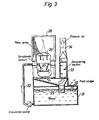
- Fig. 3 shows an embodiment of a spray booth for spray painting and having a container for collecting the spray booth liquid, which circulates between the spray booth and the container.
- the object 29 to be painted is placed in the upper portion 28 of the spray booth and the air contaminated with paint is caused to flow through a venturi 30 in which this air and the liquid are intimately mixed so that paint particles and solvent are transferred from the air to the liquid.
- the liquid in this case water, is circulated from the container 31 through the conduit 32 and through the venturi 30.
- the air flowing into the venturi contains paint particles and gaseous solvent.
- Fig. 4 shows the biotower 6 in two sideviews, one partly sectioned.
- the tower contains a filling material acting as the matrix for bacterial growth and action.
- the tower is placed on a settling tank 37 and the filling material is supported by a stainless steel grid 38 arranged in the tank cover.
- Water is supplied to the top of the biotower through a conduit 14, where it is freely distributed over the packing and during the downward migration of the water the solvent is absorbed and metabolized in the layer of microorganisms covering the packing material.
- the water is then collected in the tank 37 and is supplied to the microflotation unit through a conduit 39.
- Air is supplied through a lower duct 40 and is drawn through the tower from bottom to top in counter flow to the water flow and led away through an upper duct 41.
- the microflotation unit is shown in Fig. 5 from above and in a sectioned sideview in Fig. 6.
- dead organisms are separated from the water coming from the tank 37 of the biotower 36.
- a minor portion of the cleaned water is pressurized by means of high-pressure pump 42 and is then saturated with compressed air in a pressure tank 43. At this high pressure the water is capable of dissolving 80-100 ml of air per litre of water.
- This pressurized water is then expanded in a tank 44 to which the overflow conduit 39 from the biotower is also connected.
- This process is performed such that the air dispersion is transported through a conduit 45 which also serves to distribute air and introduce it into the lower portion of the expansion tank 44, to which the biosludge from the biotower is supplied via the conduit 39.
- a baffle plate 46 will force the incoming flow of fluid upwards, in order to mix with the pressurized water expanding in the container, and due to the pressure release micro- skopic air bubbles are formed which become attached to the suspended solids causing them to float to the surface.
- the solids, which are dead microorganisms can be removed by means of a skimmer or a scraping device 47, as shown in Fig. 6, comprising an endless chain 48 with two scraping members 49, for removing the pollutants or biosludge floating on the surface.
- the biosludge is transferred to a smaller tank 50 located next to the main tank 44, while the cleaned water is recirculated both to the top of the biotower and to the circulation system passing through the spray booth, as indicated in Figs. 1 and 2.
- the biosludge is then transferred to the bioreactor section via the conduit 16, for final degradation.
- a paint killer TEXO LP 781 (RTM) is introduced into the water circulating through the spray booth 1 in such quantity that the pH-value is about 8.
- the paint killer makes the paint non-sticky in the water so that it does not stick to the apparatus.
- the effect of the paint killer decreases at a pH below 8.
- the temperature of the spray booth water assumes approximately the wet temperature of the air, in this case about 12° 15°C.
- the pressure drop over the spray booth venturi is about 130-140 mm water column.
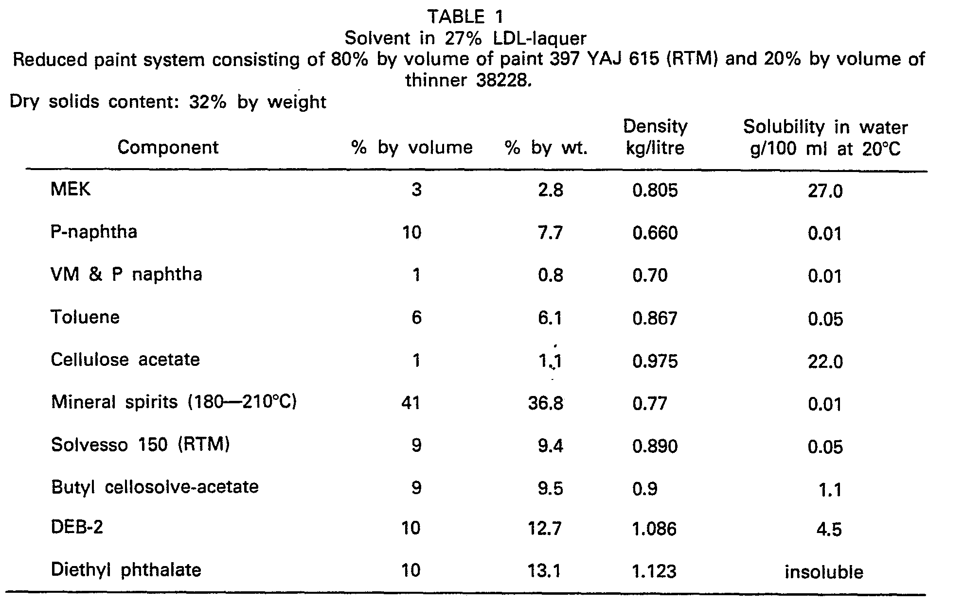
- Paint according to Table 1 is sprayed in the booth at a rate of 2-2.5 kg/h for 5-7 hours daily. Of the solvents present in the paint about two thirds by weight are separated such that about one third is absorbed in the spray booth water and another third is trapped in the paint sludge. The paint sludge is removed as required, by skimming the surface in the tank as indicated in Fig. 1. A partial flow of about 5 I/minute of spray booth water is supplied to the biotower 12 via the stabilization tank 8 and the sand filter 11. Nutrients, substantially nitrogen in the form of ammonium hydroxide and phosphor in the form of phosphoric acid are added to the stabilization tank 8. Ammonium hydroxide is added to the extent of 60 ml per kg sprayed paint and phosphoric acid to the extent of 4 ml per kg sprayed paint.
- the biotower 12 is shown in detail in Fig. 4 and has a filter of the type known as "Norton Actifil 90" (RTM).
- RTM Norton Actifil 90
- a biomass consisting of a bacteria culture grows on the filter. This culture was taken from municiple sewage plant and the species of the microorganisms grown on the filler are apparent from Table 2. The microorganisms collected from the sewage plant have to become aclimatized to their new environment before any considerable biodegradation will occur. Water was distributed over the filler to an amount of about 50-55 litres/min. The water was then collected in the bottom of the tower together with the biosludge removed from the filler material. Ambient air was sucked through the tower from the bottom to the top to oxygenate the water and the microorganisms.
- RTM Norton Actifil 90
- the solvents absorbed in the spray booth water are degradated in the . biotower.
- the degradation releases heat which makes the temperature in the biotower water some degrees higher than that in the spray booth.
- Suitable pH-values in the biotower are 6-9, which means that in this experiment the spray booth water had correct pH. If this were not the case the pH-value could have been adjusted by adding sulphuric acid or caustic soda.
- the water with biosludge from the biotower is supplied to a microflotation unit 13 which will be seen in detail in Figs. 5 and 6, where biosludge is separated whereafter the water is pumped to the top of the tower 12.
- the microflotation unit is of the "dissolved air" type, i.e. a minor portion of the cleaned water is pressurized to 4-6 bar by compressed air in a tank.
- the pressurized water is mixed with water coming into the flotation plant.
- the sudden pressure decrease of the previously pressurized water creates microscopic air bubbles which adhere to the suspended solids, i.e. dead microorganisms which then float to the surface where they are skimmed off at intervals and collected in a special tank included in the plant.
- the same amount of water, 5.litres/min, which is supplied to the biotower 12 is fed back to the spray booth 1 from the microflotation unit 13. Water evaporates from the spray booth as well as from the biotower and this loss is covered by a daily addition of about 120-130 litres of water.
- the water system contains about 4000 litres, in total, with the spray booth containing about 800 litres.
- the concentration of solvent in the water will increase and after the spraying operation it will decrease to its initial values as a result of the biological degradation in the bioreactor.
- a plant according to Fig. 2 the water from the spray booth is fed directly into a microflotation plant as shown in detail in Figs. 5 and 6. Cleaned water from the microflotation unit 13 is re-. circulated to the spray booth 1. Water from the biotower 12 is also supplied to the micrbflotation plant and clean water from the plant is recirculated to the top of said biotower. Paint sludge and biosludge are consequently separated simultaneously. The sludge is treated in two series-connected bioreactors 24 and 25.
- the first bioreactor comprises a container with a volume of about 300 litres.
- the container is ventilated with air at a pressure of about 1 bar.
- the ventilation causes mixing and oxygenation.
- the concentration of the paint sludge will be decreased by the addition of water to about 5% dry substance.
- Nitrogen in the form of ammonia and phosphorus in the form of phosphoric acid are also added. This is of course not necessary if sufficient nutrients are supplied in some other way.
- Sludge and water are transferred to the second reactor via an overflow.
- the second reactor has a volume of about 250 litres and is likewise ventilated. Water and sludge from this second reactor are finally led to a sedimentation tank 26.
- a mixture of paint sludge and biosludge to a quantity of about 3.2-3.6 kg per 24 hours with and about 50% water content comes from the bottom of the sedimentation tank.
- Cleaned water from the overflow is recirculated to the first reactor to decrease the concentration of influent sludge.
- the biodegradation occurs with the aid of a cultivation described in Example 1. If the spray booth is connected in accordance with Example 1 no further bacterial grafting is necessary since there are bacteria enough in the water.
- a suitable pH-value is 6-9, which means, that the spray booth water described in Example 1 maintains the right value. The temperature will be about the same as that of the spray booth water.
Landscapes
- Engineering & Computer Science (AREA)
- Life Sciences & Earth Sciences (AREA)
- Chemical & Material Sciences (AREA)
- Biotechnology (AREA)
- Organic Chemistry (AREA)
- General Chemical & Material Sciences (AREA)
- Microbiology (AREA)
- Environmental & Geological Engineering (AREA)
- Water Supply & Treatment (AREA)
- Biodiversity & Conservation Biology (AREA)
- Chemical Kinetics & Catalysis (AREA)
- Oil, Petroleum & Natural Gas (AREA)
- Analytical Chemistry (AREA)
- Hydrology & Water Resources (AREA)
- Toxicology (AREA)
- Health & Medical Sciences (AREA)
- Treating Waste Gases (AREA)
- Biological Treatment Of Waste Water (AREA)
- Purification Treatments By Anaerobic Or Anaerobic And Aerobic Bacteria Or Animals (AREA)
- Gas Separation By Absorption (AREA)
- Apparatus Associated With Microorganisms And Enzymes (AREA)
Abstract
Description
- The present invention relates to a plant for spray painting and purifying contaminated air, comprising a spray booth through which the contaminated air is caused to pass in intimate contact with a purified flowing liquid, whereby the contaminants are transferred from the air and a liquid having suspended and/or dissolved contamination in the form of solvents and paint particles is obtained as defined in the preamble of
claim 1. - It is previously well known, for instance in spray painting to utilize a spray bpoth, in which the object to be painted is placed so that the excess paint will accompany an air stream through the booth which is brought into intimate contact with the spray booth liquid, whereon pigment and solvent are absorbed by said liquid, thus purifying the air. The liquid flowing through the spray booth is usually water which circulates in a closed system and since the hydrocarbon-based solvents present in paint have limited solubility in water its saturation limit will very soon be reached, and as a result thereof the hydrocarbon concentration in the air which has passed through the spray booth will be unacceptably high. This means of course that persons in the room where spray painting is in progress will be exposed to health hazards. The authorities have observed the problem and in the United States for instance, hydrocarbon emission regulations have been imposed by the U.S. federal state and local governements. Inter alia, these emission regulations require that in painting with specific laquer topcoat paints there must be a hydrocarbon emission reduction of approximately 80%. This goal can only be reached by combining different measures so as to give the desired effect. Such measure include using other and harmless paints, introducing changes into the painting process, e.g. utilizing electrostatic painting and employing hydrocarbon emission abatement systems after the painting station. Large and expensive abatement systems have been installed to take care of the solvent-contaminated air from the spray booth by passing it through an activated carbon purifying plant or some kind of scrubber in which the solvents from the spray booth are washed out. According to another type of air purification, the solvent-contaminated air is passed through an incineration oven or some other kind of heating arrangement where the poisonous airborne hydrocarbon compounds are burnt.
- In the prior art there are examples, e.g. as described in DE-B 25 47 675, of plants for purifying air which employ a scrubber, where the circulating scrubbing liquid'is passed through a biological purification step. To use such a plant for purifying the exhaust air from a paint booth will be extremely costly, however, since the plant must be dimensioned for the great air quantities which flow through a spray booth, and in practice the problem has therefore not been solved in this way, due to the high costs involved.
- Consequently, it has hitherto not been possible to solve both the economical and the practical problems which are related to the hydrocarbon emission from spray booth air, and those systems which have proved to be practical solutions have not met the minimum emission regulations which the authorities have imposed and which shall already be met by the middle of this decade.
- The object of the plant according to the present invention is to provide a practical solution to purifying spray booth air which meets the demands for a good working environment as well as being economical enough to use in the manufacture of painted products at a price which is commercially viable.
- This object is realized according to the invention substantially in that first transporting means are provided for continuously drawing a portion of said liquid flowing through the closed spray booth circulation circuit therefrom and transferring it to the biological reactor and that second transporting means are provided to return essentially the same quantity of purified liquid to the closed spray booth circulation circuit.
- In a suitable embodiment of a plant according to the invention said first and second transporting means are connected to the closed spray booth circulation circuit to form a first closed circulation circuit comprising said biological reactor and said separator and wherein third transporting means are provided for connecting an output of said separator with an input of said biologicarreactor to form a second closed circulation circuit.
- In another embodiment of the invention, the container and the separator form a combined unit connected in the closed spray booth circulation circuit, and wherein said first transporting means are connecting an output of said combined unit and an input of said biological reactor, and wherein said second transporting means are connecting an output of said biological reactor with an input of said combined unit to the biological reactor, to form a closed circulation circuit.
- Some embodiments of the invention will now be described by way of example, while referring to the accompanying drawings on which
- Fig. 1 illustrates a plant for spray painting where only part of the contaminated water in the closed circuit of the spray booth is supplied to the biological step,
- Fig. 2 illlustrates an alternative embodiment of a plant for spray painting in which the container and the separator form a single unit,
- Fig. 3 illustrates in more detail the spray booth intended to form a part of the plant according to Fig. 1,
- Fig. 4 is a detail of a biological tower forming part of a plant according to Fig. 1 or Fig. 2.
- Figs. 5 and 6 are views of a microflotation unit from above and laterally, respectively, forming part of a plant according to Fig. 1 or Fig. 2.
- The plant according to Fig. 1 includes a
spray booth 1 intended for use in spray painting objects in a way which is described more in detail in connection with Fig. 2. Fans (not shown) or other air pressurizing means generate an air stream through the spray booth, causing theair 2 contaminated with paint particles to enter the upper part 3 of the spray booth, where the air is brought into intimate contact with a liquid 4, which also flows through the spray booth. The liquid is preferably water. The water contaminated thus is then collected in acontainer 5, which is arranged in the lower portion of the spray booth, and the water in the container is then recirculated to the upper portion 3 of the spray booth by means generating pressure, such as a pump 6. In accordance with the invention part of the contaminated water circulating through the spray booth is transferred to a biological purification step, the water is thus first taken via a conduit 7 to astabilization tank 8, where nutrients are added. As known in the art, these nutrients may comprise nitrogen and phosphorous compounds, e.g. ammonium hydroxide (NH40H) and phosphoric acid. The nutrients are supplied to the stabilization tank batchwise in proportion to the paint concentration in the air. The tank is kept filled and the excess liquid is returned to thecontainer 5 in the spray booth through a conduit 9. A minor flow departs from the tank via aconduit 10 to a sand filter 11. The particles suspended in the water are separated from the solvent-laden water in a sand filter which preferably comprises a pressure chamber which is filled with sand of suitable grain size. The water passes from top to bottom through the filter and two filters are preferably used for alternate connection into the circuit, so that one filter could be in operation, while the other is cleaned by means of water and pressurized air which are caused to flow backwards through the filter. From the filter the liquid flows into a bioreactor, preferably in the form of a biotower. This tower contains a filler material on which the microorganisms are grown. The total efficiency of the tower may be substantially increased by moderating pH-value and temperature, as well as the concentration of the solvents and nutrients. The changes in these influencing factors may be effected in a separation unit coming after the biotower in the closed purification liquid circuit. The separation unit is here made in the form of amicroflotation unit 13 receiving water from the bottom of the tower via aconduit 38 and delivering treated water in a separate continuous circulation process via aconduit 14 to the top of the tower. It is of course evident that other reactors could be used instead of a biotower, for instance in the form of a fluidized bed or an activated sludge tank. In themicroflotation unit 13 the dead microorganisms are separated from the water coming from the biotower and the cleaned water goes back to thecontainer 5 via aconduit 15. The separated biosludge then flows through afurther conduit 16 to anotherbioreactor 17, to which the paint sludge separated in thecontainer 5 is also supplied through aconduit 18. Thebioreactor 17 is in this case an activated sludge tank, which means the air must be supplied to the tank for accomplishing the desired aerobic degradation. Theconduit 18 is connected to asurface separator 19 in thecontainer 5, and this separator can also be combined with a bottom separator (not shown) from which the paint sludge is supplied through aconduit 20 to thebioreactor 17. The residual sludge is finally discharged from the bioreactor to a recovery plant. Thebioreactor 17 can naturally be in the form of a passive sludge bed such as a digestion tank in which the final degradation or organic material occurs anaerobically. - Fig. 2 shows an alternative embodiment of a spray painting plant where the
container 15 andseparator 13 according to Fig. 1 are arranged in asingle unit 21 which is consequently part of the spray booth liquid circulation circuit and the biological purification step. The contaminated liquid from thespray booth 1 is supplied throughconduits 22 directly to theseparator 21, which is in the form of a microflotation unit in this embodiment also. The same quantity of liquid taken from the spray booth throughconduits 22 is tapped out from themicroflotation unit 21 and . recirculated to thespray booth 1 through aconduit 23 by means of a pump 6. Themicroflotation unit 21 and thebiotower 12 have a separate liquid circulation circuit, similar to that described in connection with Fig. 1, viaconduits separator 21 to the top of thebiotower 12 and from its bottom to the separator. The nutrients which are necessary for the biological purification are supplied in this embodiment to the liquid which is recirculated to the top of the biotower. Theseparator 21 here is consequently given the double function of separating the impurities suspended in the spray booth liquid and also the biosludge coming from the biotower. The biosludge is then transferred viaconduit 16 to the bioreactor section. In this plant there are two series-connectedbioreactors 24 and 251 both being of the activated sludge type. Water and sludge from thesecond reactor 25 are supplied to asedimentation tank 26, from which cleaned water is recirculated to thefirst reactor 24 via aconduit 27. - Fig. 3 shows an embodiment of a spray booth for spray painting and having a container for collecting the spray booth liquid, which circulates between the spray booth and the container. The
object 29 to be painted is placed in theupper portion 28 of the spray booth and the air contaminated with paint is caused to flow through aventuri 30 in which this air and the liquid are intimately mixed so that paint particles and solvent are transferred from the air to the liquid. The liquid, in this case water, is circulated from thecontainer 31 through theconduit 32 and through theventuri 30. The air flowing into the venturi contains paint particles and gaseous solvent. Due to the intimate contact in the venturi between the liquid and the air, the particles and solvent are transferred from the air and to the liquid, and after the venturi the liquid, now laden with paint particles and solvent is separated from the air in adewatering section 33 from which the liquid is caused to flow back to thecontainer 31, while the air departs through anexhaust duct 34. The paint sludge in thecontainer 31 floats on the surface where it can easily be removed by means of a skimming device as is indicated in Fig. 1. Gaseous solvent is prevented from being entrained in the air stream from the spray booth by means of awater trap 35. - Fig. 4 shows the biotower 6 in two sideviews, one partly sectioned. The tower contains a filling material acting as the matrix for bacterial growth and action. The tower is placed on a
settling tank 37 and the filling material is supported by astainless steel grid 38 arranged in the tank cover. Water is supplied to the top of the biotower through aconduit 14, where it is freely distributed over the packing and during the downward migration of the water the solvent is absorbed and metabolized in the layer of microorganisms covering the packing material. The water is then collected in thetank 37 and is supplied to the microflotation unit through aconduit 39. Air is supplied through alower duct 40 and is drawn through the tower from bottom to top in counter flow to the water flow and led away through anupper duct 41. - The microflotation unit is shown in Fig. 5 from above and in a sectioned sideview in Fig. 6. In the microflotation unit dead organisms are separated from the water coming from the
tank 37 of thebiotower 36. A minor portion of the cleaned water is pressurized by means of high-pressure pump 42 and is then saturated with compressed air in apressure tank 43. At this high pressure the water is capable of dissolving 80-100 ml of air per litre of water. This pressurized water is then expanded in a tank 44 to which theoverflow conduit 39 from the biotower is also connected. This process is performed such that the air dispersion is transported through aconduit 45 which also serves to distribute air and introduce it into the lower portion of the expansion tank 44, to which the biosludge from the biotower is supplied via theconduit 39. Abaffle plate 46 will force the incoming flow of fluid upwards, in order to mix with the pressurized water expanding in the container, and due to the pressure release micro- skopic air bubbles are formed which become attached to the suspended solids causing them to float to the surface. The solids, which are dead microorganisms, can be removed by means of a skimmer or ascraping device 47, as shown in Fig. 6, comprising anendless chain 48 with two scrapingmembers 49, for removing the pollutants or biosludge floating on the surface. The biosludge is transferred to asmaller tank 50 located next to the main tank 44, while the cleaned water is recirculated both to the top of the biotower and to the circulation system passing through the spray booth, as indicated in Figs. 1 and 2. The biosludge is then transferred to the bioreactor section via theconduit 16, for final degradation. - In a plant according to Fig. 1, water at 80 I/min and air at 0.5 m3/sec are caused to flow through a spray booth which is shown in detail in Fig. 3.
- A paint killer TEXO LP 781 (RTM) is introduced into the water circulating through the
spray booth 1 in such quantity that the pH-value is about 8. The paint killer makes the paint non-sticky in the water so that it does not stick to the apparatus. The effect of the paint killer decreases at a pH below 8. - The temperature of the spray booth water assumes approximately the wet temperature of the air, in this case about 12° 15°C. The pressure drop over the spray booth venturi is about 130-140 mm water column.
- Paint according to Table 1 is sprayed in the booth at a rate of 2-2.5 kg/h for 5-7 hours daily. Of the solvents present in the paint about two thirds by weight are separated such that about one third is absorbed in the spray booth water and another third is trapped in the paint sludge. The paint sludge is removed as required, by skimming the surface in the tank as indicated in Fig. 1. A partial flow of about 5 I/minute of spray booth water is supplied to the
biotower 12 via thestabilization tank 8 and the sand filter 11. Nutrients, substantially nitrogen in the form of ammonium hydroxide and phosphor in the form of phosphoric acid are added to thestabilization tank 8. Ammonium hydroxide is added to the extent of 60 ml per kg sprayed paint and phosphoric acid to the extent of 4 ml per kg sprayed paint. - The
biotower 12 is shown in detail in Fig. 4 and has a filter of the type known as "Norton Actifil 90" (RTM). A biomass consisting of a bacteria culture grows on the filter. This culture was taken from municiple sewage plant and the species of the microorganisms grown on the filler are apparent from Table 2. The microorganisms collected from the sewage plant have to become aclimatized to their new environment before any considerable biodegradation will occur. Water was distributed over the filler to an amount of about 50-55 litres/min. The water was then collected in the bottom of the tower together with the biosludge removed from the filler material. Ambient air was sucked through the tower from the bottom to the top to oxygenate the water and the microorganisms. The solvents absorbed in the spray booth water are degradated in the . biotower. The degradation releases heat which makes the temperature in the biotower water some degrees higher than that in the spray booth. Suitable pH-values in the biotower are 6-9, which means that in this experiment the spray booth water had correct pH. If this were not the case the pH-value could have been adjusted by adding sulphuric acid or caustic soda. - The water with biosludge from the biotower is supplied to a
microflotation unit 13 which will be seen in detail in Figs. 5 and 6, where biosludge is separated whereafter the water is pumped to the top of thetower 12. The microflotation unit is of the "dissolved air" type, i.e. a minor portion of the cleaned water is pressurized to 4-6 bar by compressed air in a tank. The pressurized water is mixed with water coming into the flotation plant. The sudden pressure decrease of the previously pressurized water creates microscopic air bubbles which adhere to the suspended solids, i.e. dead microorganisms which then float to the surface where they are skimmed off at intervals and collected in a special tank included in the plant. The same amount of water, 5.litres/min, which is supplied to thebiotower 12 is fed back to thespray booth 1 from themicroflotation unit 13. Water evaporates from the spray booth as well as from the biotower and this loss is covered by a daily addition of about 120-130 litres of water. The water system contains about 4000 litres, in total, with the spray booth containing about 800 litres. - During spray painting the concentration of solvent in the water will increase and after the spraying operation it will decrease to its initial values as a result of the biological degradation in the bioreactor.
- The solvent concentration is most easily measured with a TOC-instrument (TOC=Total Organic Carbon) and in this case a Beckman 915 TOC is used.
- The conclusion is that for a quantity of about 12-13 kg paint sprayed per day about 6 kg solvent will be separated, and therefore 3 kg per 24 hours will be degradated in the bioreactor.
- In a plant according to Fig. 2 the water from the spray booth is fed directly into a microflotation plant as shown in detail in Figs. 5 and 6. Cleaned water from the
microflotation unit 13 is re-. circulated to thespray booth 1. Water from thebiotower 12 is also supplied to the micrbflotation plant and clean water from the plant is recirculated to the top of said biotower. Paint sludge and biosludge are consequently separated simultaneously. The sludge is treated in two series-connectedbioreactors - Of the 12-13 kgs of paint sprayed during a day according to Example 1 about 4-5 kgs of dry substance forms together with about 3 kgs of solvent contained in it a sludge cake with about 50% water contant. This sludge cake is transferred to the two series connected
bioreactors - Nitrogen in the form of ammonia and phosphorus in the form of phosphoric acid are also added. This is of course not necessary if sufficient nutrients are supplied in some other way.
- Sludge and water are transferred to the second reactor via an overflow. The second reactor has a volume of about 250 litres and is likewise ventilated. Water and sludge from this second reactor are finally led to a
sedimentation tank 26. A mixture of paint sludge and biosludge to a quantity of about 3.2-3.6 kg per 24 hours with and about 50% water content comes from the bottom of the sedimentation tank. - Cleaned water from the overflow is recirculated to the first reactor to decrease the concentration of influent sludge.
- The biodegradation occurs with the aid of a cultivation described in Example 1. If the spray booth is connected in accordance with Example 1 no further bacterial grafting is necessary since there are bacteria enough in the water. A suitable pH-value is 6-9, which means, that the spray booth water described in Example 1 maintains the right value. The temperature will be about the same as that of the spray booth water.
- The conclusion here is that about 3 kg of solvent contained in the paint sludge and part of the paint binder have been broken down.

Claims (7)
characterized in that first transporting means are provided for continuously drawing a portion of said liquid flowing through the closed spray booth circulation circuit therefrom and transferring it to the biological reactor and that second transporting means are provided to return essentially the same quantity of purified liquid to the closed spray booth circulation circuit.
Priority Applications (1)
| Application Number | Priority Date | Filing Date | Title |
|---|---|---|---|
| AT82850089T ATE22275T1 (en) | 1981-05-08 | 1982-04-28 | PLANT FOR CLEANING POLLUTED AIR. |
Applications Claiming Priority (2)
| Application Number | Priority Date | Filing Date | Title |
|---|---|---|---|
| SE8102901 | 1981-05-08 | ||
| SE8102901A SE443930B (en) | 1981-05-08 | 1981-05-08 | DEVICE FOR PURIFICATION OF POLLUTANEATED AIR FROM A SPRAYBOX WITH A BIOLOGICAL DEGRADATION |
Publications (2)
| Publication Number | Publication Date |
|---|---|
| EP0064960A1 EP0064960A1 (en) | 1982-11-17 |
| EP0064960B1 true EP0064960B1 (en) | 1986-09-17 |
Family
ID=20343776
Family Applications (1)
| Application Number | Title | Priority Date | Filing Date |
|---|---|---|---|
| EP19820850089 Expired EP0064960B1 (en) | 1981-05-08 | 1982-04-28 | A plant for purifying contaminated air |
Country Status (8)
| Country | Link |
|---|---|
| US (1) | US4472181A (en) |
| EP (1) | EP0064960B1 (en) |
| JP (1) | JPS57202283A (en) |
| AT (1) | ATE22275T1 (en) |
| AU (1) | AU554774B2 (en) |
| CA (1) | CA1175169A (en) |
| DE (1) | DE3273287D1 (en) |
| SE (1) | SE443930B (en) |
Families Citing this family (26)
| Publication number | Priority date | Publication date | Assignee | Title |
|---|---|---|---|---|
| US4585557A (en) * | 1984-01-04 | 1986-04-29 | Turnquist Sanfred E | Apparatus for concentrating, separating and removing floating solid material |
| US4722791A (en) * | 1984-01-04 | 1988-02-02 | Turnquist Sanfred E | Methods for detackifying, floating, concentrating, separating and removing floating solid paint material |
| US4610785A (en) * | 1985-01-03 | 1986-09-09 | Protectaire Systems Co. | Sludge separation apparatus |
| AT382323B (en) * | 1985-10-24 | 1987-02-10 | Linzer Glasspinnerei Franz Hai | METHOD AND DEVICE FOR PURIFYING RAW GAS |
| US4976751A (en) * | 1986-12-04 | 1990-12-11 | Keramchemie Gmbh | Method for purification of exhaust air |
| US4980030A (en) * | 1987-04-02 | 1990-12-25 | Haden Schweitzer | Method for treating waste paint sludge |
| US4750919A (en) * | 1987-10-23 | 1988-06-14 | Nalco Chemical Company | Paint removal using oil-in-water emulsions |
| SE466735B (en) * | 1990-07-13 | 1992-03-30 | Flaekt Ab | PROCEDURE AND DEVICE FOR WATER CLEANING WITH BIOLOGICAL CLEANING OF THE WATER USED |
| EP0502232B1 (en) * | 1991-03-07 | 1993-05-19 | Parkner GmbH | Process for disposal of organic sludge, especially of paint sludge, originating from a coating installation |
| US5279963A (en) * | 1991-04-18 | 1994-01-18 | Hobby Michael M | System for the decontamination of a contaminated gas |
| US5360539A (en) * | 1992-07-27 | 1994-11-01 | Abb Flakt Aktiebolag | Scrubbing water handling system for paint spray booths |
| US6027566A (en) * | 1994-02-24 | 2000-02-22 | Blowtherm Canada, Inc. | Paint spray booth |
| DE19732207C1 (en) * | 1997-07-26 | 1998-11-26 | Olt Oberflaechen Luft Und Troc | Removal of paint spray particles from water suspension |
| US6312649B2 (en) * | 1997-11-14 | 2001-11-06 | Bedminster Ab | Bio-tower |
| ITMC20010041A1 (en) * | 2001-04-12 | 2002-10-12 | Massimo Pierini | PLANT FOR THE ABATEMENT OF EMISSIONS IN THE ATMOSPHERE OF ORGANIC SOLVENTS FOR THE DILUTION OF PAINTS. |
| ES2394305T3 (en) * | 2002-12-11 | 2013-01-30 | Taiheiyo Cement Corporation | Cement kiln chlorine / sulfur bypass system |
| ATE437660T1 (en) * | 2004-03-24 | 2009-08-15 | Bbr Biofiltration Proprietary | PURIFYING CONTAMINATED AIR |
| US7754023B2 (en) * | 2004-12-03 | 2010-07-13 | Ppg Industries Ohio, Inc. | Compositions and methods using a microorganism concentrate for paint overspray removal processes |
| KR101305396B1 (en) * | 2005-09-26 | 2013-09-05 | 에이치플러스에코 주식회사 | Paint detackification agent |
| US8202424B2 (en) * | 2007-01-29 | 2012-06-19 | Atotech Deutschland Gmbh | Microbial degradation of water-borne paint containing high levels of organic solvent |
| EP2522415B1 (en) * | 2011-05-11 | 2015-05-06 | Metso Minerals (Deutschland) GmbH | Device for purifying waste air from industrial shredder assemblies |
| US20150157972A1 (en) * | 2013-12-09 | 2015-06-11 | Keith Bratten | Demister Apparatus and Method |
| JP6347359B2 (en) * | 2014-01-31 | 2018-06-27 | 三菱重工エンジニアリング株式会社 | Gas absorption / regeneration device and operation method thereof |
| CN110115895A (en) * | 2019-06-18 | 2019-08-13 | 波态(上海)新材料科技有限公司 | A kind of coating coating cloud processing method |
| WO2022235623A1 (en) | 2021-05-06 | 2022-11-10 | Ecolab Usa Inc. | Systems and processes for injecting gas-infused additives |
| CN114748879B (en) * | 2022-05-11 | 2025-02-14 | 天华化工机械及自动化研究设计院有限公司 | A large-scale spray drying system with nitrogen closed circulation for organic solvents |
Family Cites Families (22)
| Publication number | Priority date | Publication date | Assignee | Title |
|---|---|---|---|---|
| BE415615A (en) * | 1936-05-13 | |||
| US2141979A (en) * | 1936-09-25 | 1938-12-27 | Halvorson H Orin | Process for treating sewage to purify the same |
| USRE22144E (en) * | 1939-09-30 | 1942-07-21 | Sewage treatment | |
| US2642394A (en) * | 1948-06-18 | 1953-06-16 | Infilco Inc | Two-stage aerobic biological sewage treating process and system |
| NL270612A (en) * | 1960-09-21 | |||
| US3853764A (en) * | 1964-04-23 | 1974-12-10 | E Armstrong | Waste water treatment system |
| US3396514A (en) * | 1966-11-07 | 1968-08-13 | Babcock & Wilcox Co | Gas cleaning system |
| US3713543A (en) * | 1968-09-23 | 1973-01-30 | Dravo Corp | Activated sewage plant |
| JPS5129325A (en) * | 1974-09-06 | 1976-03-12 | Tokyo Kagaku Sochi Kk | METSUKISHORIN YORUHAISUI NO SAISHOHOHO |
| FR2290938A1 (en) * | 1974-11-18 | 1976-06-11 | Air Ind | METHOD AND INSTALLATION FOR CONTINUOUS TREATMENT OF A GAS WASHING LIQUID |
| JPS51106678A (en) * | 1975-03-17 | 1976-09-21 | Fuji Kasui Kogyo Kk | |
| GB1540723A (en) * | 1975-05-07 | 1979-02-14 | Carrier Drysys Ltd | Treating waste paint solids |
| US4092242A (en) * | 1975-06-16 | 1978-05-30 | The Redux Corporation | Waste water purification system |
| US4008056A (en) * | 1975-09-29 | 1977-02-15 | George Potter | Scrubber system for removing gaseous pollutants from a moving gas stream by condensation |
| JPS5247701A (en) * | 1975-10-14 | 1977-04-15 | Mazda Motor Corp | Sound-proof and vibration-insulating coating materials for sheet metal s for vehicles |
| DE2547675B2 (en) * | 1975-10-24 | 1978-06-01 | Daimler-Benz Ag, 7000 Stuttgart | Process for the wet cleaning of polluted exhaust air |
| JPS5347807A (en) * | 1976-10-13 | 1978-04-28 | Shigeo Tsukagoshi | Loop endless tape continuous reproducer and device therefor with cassette |
| FI54595C (en) * | 1978-01-24 | 1979-01-10 | Asko Upo Oy | KOMBINATION AV BIOLOGISK TORRTOALETT OCH BIOLOGISK RENGOERINGSANLAEGGNING FOER AVLOPPSVATTEN |
| FI790165A7 (en) * | 1978-02-06 | 1979-08-07 | Itt | FOERFARANDE FOER SEKUNDAER BEHANDLING AV AVFALLSVATTEN |
| US4200524A (en) * | 1978-10-25 | 1980-04-29 | Biospherics Incorporated | Bio-surface separation process |
| CA1114963A (en) * | 1979-10-26 | 1981-12-22 | Canadian Industries Limited | Means for separation of gas and solids from waste mixed liquor |
| CA1114960A (en) * | 1979-10-26 | 1981-12-22 | Canadian Industries Limited | Method for the froth flotation separation and treatment of slowly biodegradable components in a waste treatment system |
-
1981
- 1981-05-08 SE SE8102901A patent/SE443930B/en not_active IP Right Cessation
-
1982
- 1982-04-14 US US06/368,411 patent/US4472181A/en not_active Expired - Fee Related
- 1982-04-21 CA CA000401385A patent/CA1175169A/en not_active Expired
- 1982-04-28 AT AT82850089T patent/ATE22275T1/en active
- 1982-04-28 EP EP19820850089 patent/EP0064960B1/en not_active Expired
- 1982-04-28 DE DE8282850089T patent/DE3273287D1/en not_active Expired
- 1982-05-07 JP JP7739982A patent/JPS57202283A/en active Granted
- 1982-05-07 AU AU83487/82A patent/AU554774B2/en not_active Ceased
Also Published As
| Publication number | Publication date |
|---|---|
| US4472181A (en) | 1984-09-18 |
| JPH0446608B2 (en) | 1992-07-30 |
| CA1175169A (en) | 1984-09-25 |
| EP0064960A1 (en) | 1982-11-17 |
| AU554774B2 (en) | 1986-09-04 |
| AU8348782A (en) | 1982-11-11 |
| DE3273287D1 (en) | 1986-10-23 |
| ATE22275T1 (en) | 1986-10-15 |
| JPS57202283A (en) | 1982-12-11 |
| SE8102901L (en) | 1982-12-08 |
| SE443930B (en) | 1986-03-17 |
Similar Documents
| Publication | Publication Date | Title |
|---|---|---|
| EP0064960A1 (en) | A plant for purifying contaminated air | |
| US4723968A (en) | Method and apparatus for the purification of waste air containing biologically decomposable impurities | |
| US3112261A (en) | Apparatus and method for promoting biological oxidation of organic material | |
| EP0695722A1 (en) | Apparatus and method for waste water treatment utilizing aerobic and anaerobic microorganisms | |
| US5077025A (en) | Process or purifying waste gases by scrubbing with an adsorbent suspension | |
| WO2020073110A1 (en) | System and method for purifying waste gases of organic compounds | |
| US5494574A (en) | Mechanically mixed packed bed bioreactor | |
| DE3738295A1 (en) | REACTOR AND METHOD FOR THE BIOLOGICAL PURIFICATION OF POLLUTANT-BASED WATER | |
| JP2515552B2 (en) | Exhaust air and wastewater biological purification apparatus and method | |
| EP0282750A1 (en) | Process and apparatus for cleaning exhaust air or gases | |
| DE3628030C2 (en) | ||
| US5348654A (en) | Co-current packed tower bio-reactor | |
| US6143553A (en) | Process and materials for removing pollutants | |
| US20050150843A1 (en) | Method and device for treatment of liquids, in particular for purification of contaminated water | |
| US5853578A (en) | Method for biological purification of liquids and biological filter for purification of liquids | |
| EP0385555B1 (en) | Apparatus for carrying out a combined air and water purification, and also a method for operating such a purification | |
| AT400683B (en) | METHOD FOR AEROBIC MICROBIOLOGICAL DECONTAMINATION OF GASES | |
| JP4716811B2 (en) | VOC-containing gas processing apparatus and processing method | |
| KR20000022135A (en) | Reactor for the depuration of polluted waste waters | |
| JPH0763716B2 (en) | Biological filter bed purification device | |
| CN217127114U (en) | Oil removal, slag removal and solid removal coupling reaction device for wastewater | |
| EP0078033B1 (en) | Improved continuous process and plant for tertiary photobiological treatment of waste water | |
| KR100751002B1 (en) | Advanced Organic Wastewater Treatment System using Pyramid Reactor | |
| EP0355109A4 (en) | System and method for the extraction of cyanide from tails liquor. | |
| Dickerson et al. | Laboratory and pilot plant studies on phosphate removal from industrial wastewater |
Legal Events
| Date | Code | Title | Description |
|---|---|---|---|
| PUAI | Public reference made under article 153(3) epc to a published international application that has entered the european phase |
Free format text: ORIGINAL CODE: 0009012 |
|
| AK | Designated contracting states |
Designated state(s): AT BE CH DE FR GB IT NL SE |
|
| 17P | Request for examination filed |
Effective date: 19830324 |
|
| RAP1 | Party data changed (applicant data changed or rights of an application transferred) |
Owner name: FLAEKT AKTIEBOLAG |
|
| GRAA | (expected) grant |
Free format text: ORIGINAL CODE: 0009210 |
|
| AK | Designated contracting states |
Kind code of ref document: B1 Designated state(s): AT BE CH DE FR GB IT LI NL SE |
|
| REF | Corresponds to: |
Ref document number: 22275 Country of ref document: AT Date of ref document: 19861015 Kind code of ref document: T |
|
| ITF | It: translation for a ep patent filed | ||
| REF | Corresponds to: |
Ref document number: 3273287 Country of ref document: DE Date of ref document: 19861023 |
|
| ET | Fr: translation filed | ||
| PLBE | No opposition filed within time limit |
Free format text: ORIGINAL CODE: 0009261 |
|
| STAA | Information on the status of an ep patent application or granted ep patent |
Free format text: STATUS: NO OPPOSITION FILED WITHIN TIME LIMIT |
|
| 26N | No opposition filed | ||
| ITTA | It: last paid annual fee | ||
| PGFP | Annual fee paid to national office [announced via postgrant information from national office to epo] |
Ref country code: FR Payment date: 19930408 Year of fee payment: 12 |
|
| PGFP | Annual fee paid to national office [announced via postgrant information from national office to epo] |
Ref country code: AT Payment date: 19930415 Year of fee payment: 12 |
|
| PGFP | Annual fee paid to national office [announced via postgrant information from national office to epo] |
Ref country code: SE Payment date: 19930419 Year of fee payment: 12 Ref country code: GB Payment date: 19930419 Year of fee payment: 12 |
|
| PGFP | Annual fee paid to national office [announced via postgrant information from national office to epo] |
Ref country code: CH Payment date: 19930427 Year of fee payment: 12 |
|
| PGFP | Annual fee paid to national office [announced via postgrant information from national office to epo] |
Ref country code: NL Payment date: 19930430 Year of fee payment: 12 |
|
| PGFP | Annual fee paid to national office [announced via postgrant information from national office to epo] |
Ref country code: DE Payment date: 19930506 Year of fee payment: 12 |
|
| PGFP | Annual fee paid to national office [announced via postgrant information from national office to epo] |
Ref country code: BE Payment date: 19930608 Year of fee payment: 12 |
|
| PG25 | Lapsed in a contracting state [announced via postgrant information from national office to epo] |
Ref country code: GB Effective date: 19940428 Ref country code: AT Effective date: 19940428 |
|
| PG25 | Lapsed in a contracting state [announced via postgrant information from national office to epo] |
Ref country code: SE Effective date: 19940429 |
|
| PG25 | Lapsed in a contracting state [announced via postgrant information from national office to epo] |
Ref country code: LI Effective date: 19940430 Ref country code: CH Effective date: 19940430 Ref country code: BE Effective date: 19940430 |
|
| BERE | Be: lapsed |
Owner name: FLAKT A.B. Effective date: 19940430 |
|
| PG25 | Lapsed in a contracting state [announced via postgrant information from national office to epo] |
Ref country code: NL Effective date: 19941101 |
|
| NLV4 | Nl: lapsed or anulled due to non-payment of the annual fee | ||
| PG25 | Lapsed in a contracting state [announced via postgrant information from national office to epo] |
Ref country code: FR Effective date: 19941229 |
|
| REG | Reference to a national code |
Ref country code: CH Ref legal event code: PL |
|
| PG25 | Lapsed in a contracting state [announced via postgrant information from national office to epo] |
Ref country code: DE Effective date: 19950103 |
|
| GBPC | Gb: european patent ceased through non-payment of renewal fee |
Effective date: 19940428 |
|
| EUG | Se: european patent has lapsed |
Ref document number: 82850089.2 Effective date: 19941110 |
|
| REG | Reference to a national code |
Ref country code: FR Ref legal event code: ST |