EP0064880B1 - Method of, and apparatus for, detecting leaks - Google Patents
Method of, and apparatus for, detecting leaks Download PDFInfo
- Publication number
- EP0064880B1 EP0064880B1 EP82302390A EP82302390A EP0064880B1 EP 0064880 B1 EP0064880 B1 EP 0064880B1 EP 82302390 A EP82302390 A EP 82302390A EP 82302390 A EP82302390 A EP 82302390A EP 0064880 B1 EP0064880 B1 EP 0064880B1
- Authority
- EP
- European Patent Office
- Prior art keywords
- gas
- sampler
- sampling volume
- sample
- air
- Prior art date
- Legal status (The legal status is an assumption and is not a legal conclusion. Google has not performed a legal analysis and makes no representation as to the accuracy of the status listed.)
- Expired
Links
- 238000000034 method Methods 0.000 title claims abstract description 7
- 238000005070 sampling Methods 0.000 claims abstract description 20
- 239000000523 sample Substances 0.000 claims description 20
- 238000004519 manufacturing process Methods 0.000 claims description 14
- 238000001514 detection method Methods 0.000 claims description 3
- 230000001105 regulatory effect Effects 0.000 abstract description 2
- 239000007789 gas Substances 0.000 description 22
- 239000001307 helium Substances 0.000 description 11
- 229910052734 helium Inorganic materials 0.000 description 11
- SWQJXJOGLNCZEY-UHFFFAOYSA-N helium atom Chemical compound [He] SWQJXJOGLNCZEY-UHFFFAOYSA-N 0.000 description 11
- 238000012360 testing method Methods 0.000 description 9
- 238000007689 inspection Methods 0.000 description 2
- 230000003068 static effect Effects 0.000 description 2
- 239000004035 construction material Substances 0.000 description 1
- 238000010586 diagram Methods 0.000 description 1
- 238000009792 diffusion process Methods 0.000 description 1
- 238000002474 experimental method Methods 0.000 description 1
- 150000004820 halides Chemical class 0.000 description 1
- 238000005259 measurement Methods 0.000 description 1
- 239000000203 mixture Substances 0.000 description 1
- 231100000252 nontoxic Toxicity 0.000 description 1
- 230000003000 nontoxic effect Effects 0.000 description 1
- 230000035945 sensitivity Effects 0.000 description 1
- 238000010998 test method Methods 0.000 description 1
- 230000000007 visual effect Effects 0.000 description 1
- XLYOFNOQVPJJNP-UHFFFAOYSA-N water Substances O XLYOFNOQVPJJNP-UHFFFAOYSA-N 0.000 description 1
Images
Classifications
-
- G—PHYSICS
- G01—MEASURING; TESTING
- G01M—TESTING STATIC OR DYNAMIC BALANCE OF MACHINES OR STRUCTURES; TESTING OF STRUCTURES OR APPARATUS, NOT OTHERWISE PROVIDED FOR
- G01M3/00—Investigating fluid-tightness of structures
- G01M3/02—Investigating fluid-tightness of structures by using fluid or vacuum
- G01M3/04—Investigating fluid-tightness of structures by using fluid or vacuum by detecting the presence of fluid at the leakage point
-
- G—PHYSICS
- G01—MEASURING; TESTING
- G01M—TESTING STATIC OR DYNAMIC BALANCE OF MACHINES OR STRUCTURES; TESTING OF STRUCTURES OR APPARATUS, NOT OTHERWISE PROVIDED FOR
- G01M3/00—Investigating fluid-tightness of structures
- G01M3/02—Investigating fluid-tightness of structures by using fluid or vacuum
- G01M3/04—Investigating fluid-tightness of structures by using fluid or vacuum by detecting the presence of fluid at the leakage point
- G01M3/20—Investigating fluid-tightness of structures by using fluid or vacuum by detecting the presence of fluid at the leakage point using special tracer materials, e.g. dye, fluorescent material, radioactive material
- G01M3/202—Investigating fluid-tightness of structures by using fluid or vacuum by detecting the presence of fluid at the leakage point using special tracer materials, e.g. dye, fluorescent material, radioactive material using mass spectrometer detection systems
- G01M3/205—Accessories or associated equipment; Pump constructions
Definitions
- This invention relates to a method of, and apparatus for, detecting leaks. It is particularly, though not exclusively, concerned with detecting leaks that arise in the manufacture of assembled vehicles in the course of production.
- a method of detecting the presence of a leakage path leading to the surface of a fabrication comprising the steps of: positioning a sampler above at least part of a surface of a fabrication; providing a sample of signal gas to the end remote from the surface of a leakage path leading to the surface; establishing by means of coaxial members an air curtain between the sampler and the surface by an outflow of air from between the members, the curtain serving with the sampler and the surface to define a sampling volume; maintaining gas pressure in the sampling volume at a level below that of gas at the remote end of the leakage path; withdrawing a sample of gas from the sampling volume by means of a probe incorporated in the sampler; and passing the sample through a gas sensor to establish whether signal gas is present or absent, characterised by adjusting the relative axial positions of the said members.
- apparatus for detection of a leakage path leading to the surface of a fabrication comprising a sampler which has: a body; a probe incorporated in the body whereby a sample of gas can be withdrawn from a sampling volume adjacent an end of the body; a gas sensing system to detect the presence or absence of a signal gas in the sample; a shroud disposed coaxially about the body to define a continuous gap around the said end of the body; and a chamber from which air, or other gas, can be passed through the continuous gap to establish an air curtain around the sampling volume, characterised by adjustment means whereby the shroud is adjusted with respect to the body to determine the relative axial positions thereof.
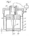
- Figure 1 shows a shrouded sampler 10 with a body 11 disposed concentrically within a shroud 12 to define an annular gap 17 therebetween.
- the position of the shroud 12 is adjustable with respect to the body 11 to permit variation, where necessary, in the setting of a margin D between the end of the shroud 12 and an end face 13 of the body 11. In use, values of D of up to 25 mm have been used.
- the body 11 is circular in cross-section and has extending through it a probe tube 14 by means of which samples of gas in the vicinity of the end face 13 can be withdrawn for passage to a gas sensor 18.
- the gas sensor 18 is a mass spectrometer adjusted to respond to traces of helium.
- a plenum chamber 15 between the body 11 and the shroud 12 is supplied with air under pressure by an inlet manifold 16.
- the passage of air through annular gap 17 from the chamber 15 provides an air curtain C (see Figure 2) around the end face 13 the use of which will be described hereafter in connection with Figures 2 to 4.
- Gas pressure in the vicinity of the end face 13 is controlled by regulating the rate of diffusion from the air curtain but may also be controlled by way of a vacuum source acting through a duct 19 and a passage 20 in the body 11.
- the pressure in this area is maintained at a level lower than that causing the gas to be driven along any leak path in a fabrication under test to the vicinity of end face 13.
- a flexible line 21 couples the sampler 10 to a work station which houses the gas sensor 18.
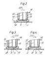
- Figures 2 to 4 show the use of the sensor shown in Figure 1 for detecting a leak in a car body.
- the car body is generally shown by the designation B and a leak path, which may for example be through a window or door seal, is shown by the designation L.
- the sampler is initially mounted adjacent the car body B and an air curtain C is established by pressurising air in the chamber 15 so that air is driven out of the annular gap 17.
- the air curtain C, the end face 13 and the upper surface of the car body B serve to define a sampling volume S.
- the sampler is driven across the car body surface in the direction shown by arrow 22.
- Figure 2 shows the air curtain C about to pass over the upper end of a leak path L in the body B. In this position, the leak path L does not communicate with the sampling volume S.
- helium gas Prior to the application of the sampler, helium gas was introduced into the car body and diffused throughout the interior thereof by a fan-type system. The interior is slightly pressurised to ensure that the resulting mixture of air and helium within the car body passes along any leak paths, such as leak path L, to the outside of the vehicle.
- air and helium pass along the leak path L from the interior of the body to the sampling volume S. Continuous sampling of gas in the volume S by means of probe 14 thus detects the presence of helium.
- Figure 4 discloses the situation when the further movement of the sampler in the direction of arrow 22 results in the air curtain C isolating the sampling volume S from the leak path L.
- the probe 14 no longer passes air containing traces of helium to the mass spectrometer.
- the mass spectrometer thus indicates that helium is no longer detected and consequently that the leak is in that part of the car body over which the sampler has passed between the positions shown in Figures 2 and 4.
- the car body B can then be inspected to detect the end of the leak path L and the movement of the sensor can be repeated to confirm visual detection of the end of the leak path L.
- the provision of the air curtain C ensures a clear definition of that part of the surface which is being scanned. It also ensures that stray traces of helium outside the car body B do not cause the probe 14 to provide spurious readings.
- the use of the pressure balancing system within the sampling volume ensures that the tendency is always for gas from the interior of the car to pass to the sampling volume S along a leak path rather than cause gas to be driven in the opposite direction into the car interior.
- Helium offers a number of advantages as a signal gas as it can be detected easily, is relatively cheap and is non-toxic. Helium is also compatible with construction materials used in vehicle manufacture and because it has a low density it can be readily dispersed from within the vehicle and the operational area following completion of a test.
- Helium is preferably mixed with air and injected into a vehicle body at a pressure of about half an inch water gauge. In this way sensitivity is improved and the response time for an inspection reduced.
- the method is particularly applicable to automatic usage on a vehicle production line.
- the body is tested prior to final assembly whilst in a partially trimmed state. This facilitates any rectification work which may prove to be necessary.
- Parts of a body shell such as door seals, windows, boot or tail gate seals and sunshine roof can be tested. Two programs for testing car bodies are envisaged.
- a car body would be passed through a test area and two manipulators would be programmed to track the body whilst in the test area.
- Each manipulator would incorporate a leak sensor which would scan the seal areas on one side of the vehicle and also one end.
- This program would have the advantage that the inspection arrangement would form part of a conventional production line layout.
- the test procedure would require the provision of a number of components which must be mobile and be programmed to return to the starting position on completion of a test cycle.
- a static bay would be provided between two moving production lines.
- a car body On reaching the final station on one line, a car body would be lifted from its track and transferred into the bay. The car body would then be lowered onto a static unit incorporating the leak sensor.
- Two manipulators one on each side of the body, would scan the seal areas under test as in the first program.
- This arrangement has the advantage of a stable datum position and fixed test services.
- the car body would be transferred to the second production line opposite that from which it had been removed.
- leak measurement would be monitored by a micro-processor control unit with preset threshold levels for the signal gas.
- the processor On detecting a leak, the processor would operate to relate the leak position to a vehicle profile display. Typically, the result would be a print-out of a vehicle diagram together with any necessary fault data.
Landscapes
- Physics & Mathematics (AREA)
- General Physics & Mathematics (AREA)
- Examining Or Testing Airtightness (AREA)
Abstract
Description
- This invention relates to a method of, and apparatus for, detecting leaks. It is particularly, though not exclusively, concerned with detecting leaks that arise in the manufacture of assembled vehicles in the course of production.
- According to a first aspect of the present invention, there is provided a method of detecting the presence of a leakage path leading to the surface of a fabrication comprising the steps of: positioning a sampler above at least part of a surface of a fabrication; providing a sample of signal gas to the end remote from the surface of a leakage path leading to the surface; establishing by means of coaxial members an air curtain between the sampler and the surface by an outflow of air from between the members, the curtain serving with the sampler and the surface to define a sampling volume; maintaining gas pressure in the sampling volume at a level below that of gas at the remote end of the leakage path; withdrawing a sample of gas from the sampling volume by means of a probe incorporated in the sampler; and passing the sample through a gas sensor to establish whether signal gas is present or absent, characterised by adjusting the relative axial positions of the said members.
- According to a second aspect of the present invention there is provided apparatus for detection of a leakage path leading to the surface of a fabrication, the apparatus comprising a sampler which has: a body; a probe incorporated in the body whereby a sample of gas can be withdrawn from a sampling volume adjacent an end of the body; a gas sensing system to detect the presence or absence of a signal gas in the sample; a shroud disposed coaxially about the body to define a continuous gap around the said end of the body; and a chamber from which air, or other gas, can be passed through the continuous gap to establish an air curtain around the sampling volume, characterised by adjustment means whereby the shroud is adjusted with respect to the body to determine the relative axial positions thereof.
- French Patent Specification No. 2 301 817A and an article entitled "Jet probe of a halide leak detector" by V. F. Rogal et al in Instruments and Experimental Techniques, Vol. 19, No. 6/2, November/December 1976, pages 1734-1736, New York (USA) each disclose a method and apparatus for detecting leaks as detailed in the pre-characterising portions of the
claims 1 and 2 of this specification. However, neither of these documents provides means for adjusting the relative axial positions of members which define an air curtain around a sampling volume. - An exemplary embodiment of the invention will now be described with reference to the accompanying drawings in which:
- Figure 1 is a sectional view of a sampler according to this invention; and Figures 2 to 4 show the sampler of Figure 1 in use.
- Figure 1 shows a shrouded
sampler 10 with abody 11 disposed concentrically within ashroud 12 to define anannular gap 17 therebetween. The position of theshroud 12 is adjustable with respect to thebody 11 to permit variation, where necessary, in the setting of a margin D between the end of theshroud 12 and anend face 13 of thebody 11. In use, values of D of up to 25 mm have been used. Thebody 11 is circular in cross-section and has extending through it aprobe tube 14 by means of which samples of gas in the vicinity of theend face 13 can be withdrawn for passage to a gas sensor 18. The gas sensor 18 is a mass spectrometer adjusted to respond to traces of helium. Aplenum chamber 15 between thebody 11 and theshroud 12 is supplied with air under pressure by aninlet manifold 16. The passage of air throughannular gap 17 from thechamber 15 provides an air curtain C (see Figure 2) around theend face 13 the use of which will be described hereafter in connection with Figures 2 to 4. Gas pressure in the vicinity of theend face 13 is controlled by regulating the rate of diffusion from the air curtain but may also be controlled by way of a vacuum source acting through aduct 19 and apassage 20 in thebody 11. The pressure in this area is maintained at a level lower than that causing the gas to be driven along any leak path in a fabrication under test to the vicinity ofend face 13. Aflexible line 21 couples thesampler 10 to a work station which houses the gas sensor 18. - Figures 2 to 4 show the use of the sensor shown in Figure 1 for detecting a leak in a car body. The car body is generally shown by the designation B and a leak path, which may for example be through a window or door seal, is shown by the designation L.
- The sampler is initially mounted adjacent the car body B and an air curtain C is established by pressurising air in the
chamber 15 so that air is driven out of theannular gap 17. The air curtain C, theend face 13 and the upper surface of the car body B serve to define a sampling volume S. The sampler is driven across the car body surface in the direction shown by arrow 22. Figure 2 shows the air curtain C about to pass over the upper end of a leak path L in the body B. In this position, the leak path L does not communicate with the sampling volume S. - Prior to the application of the sampler, helium gas was introduced into the car body and diffused throughout the interior thereof by a fan-type system. The interior is slightly pressurised to ensure that the resulting mixture of air and helium within the car body passes along any leak paths, such as leak path L, to the outside of the vehicle. In the situation shown in Figure 3, air and helium pass along the leak path L from the interior of the body to the sampling volume S. Continuous sampling of gas in the volume S by means of
probe 14 thus detects the presence of helium. Figure 4 discloses the situation when the further movement of the sampler in the direction of arrow 22 results in the air curtain C isolating the sampling volume S from the leak path L. Thereafter, theprobe 14 no longer passes air containing traces of helium to the mass spectrometer. The mass spectrometer thus indicates that helium is no longer detected and consequently that the leak is in that part of the car body over which the sampler has passed between the positions shown in Figures 2 and 4. The car body B can then be inspected to detect the end of the leak path L and the movement of the sensor can be repeated to confirm visual detection of the end of the leak path L. - The provision of the air curtain C ensures a clear definition of that part of the surface which is being scanned. It also ensures that stray traces of helium outside the car body B do not cause the
probe 14 to provide spurious readings. The use of the pressure balancing system within the sampling volume ensures that the tendency is always for gas from the interior of the car to pass to the sampling volume S along a leak path rather than cause gas to be driven in the opposite direction into the car interior. - Once a leak path is detected, the necessary rectification work can be specified.
- Helium offers a number of advantages as a signal gas as it can be detected easily, is relatively cheap and is non-toxic. Helium is also compatible with construction materials used in vehicle manufacture and because it has a low density it can be readily dispersed from within the vehicle and the operational area following completion of a test.
- Helium is preferably mixed with air and injected into a vehicle body at a pressure of about half an inch water gauge. In this way sensitivity is improved and the response time for an inspection reduced.
- The method is particularly applicable to automatic usage on a vehicle production line. The body is tested prior to final assembly whilst in a partially trimmed state. This facilitates any rectification work which may prove to be necessary. Parts of a body shell such as door seals, windows, boot or tail gate seals and sunshine roof can be tested. Two programs for testing car bodies are envisaged.
- In the first program, a car body would be passed through a test area and two manipulators would be programmed to track the body whilst in the test area. Each manipulator would incorporate a leak sensor which would scan the seal areas on one side of the vehicle and also one end. This program would have the advantage that the inspection arrangement would form part of a conventional production line layout. The test procedure would require the provision of a number of components which must be mobile and be programmed to return to the starting position on completion of a test cycle.
- In the second program, a static bay would be provided between two moving production lines. On reaching the final station on one line, a car body would be lifted from its track and transferred into the bay. The car body would then be lowered onto a static unit incorporating the leak sensor. Two manipulators, one on each side of the body, would scan the seal areas under test as in the first program. This arrangement has the advantage of a stable datum position and fixed test services. Following the test sequence, the car body would be transferred to the second production line opposite that from which it had been removed. With either program, leak measurement would be monitored by a micro-processor control unit with preset threshold levels for the signal gas. On detecting a leak, the processor would operate to relate the leak position to a vehicle profile display. Typically, the result would be a print-out of a vehicle diagram together with any necessary fault data.
Claims (5)
Priority Applications (1)
| Application Number | Priority Date | Filing Date | Title |
|---|---|---|---|
| AT82302390T ATE21279T1 (en) | 1981-05-08 | 1982-05-10 | METHOD AND DEVICE FOR LEAK DETECTION. |
Applications Claiming Priority (2)
| Application Number | Priority Date | Filing Date | Title |
|---|---|---|---|
| GB8114229 | 1981-05-08 | ||
| GB8114229 | 1981-05-08 |
Publications (2)
| Publication Number | Publication Date |
|---|---|
| EP0064880A1 EP0064880A1 (en) | 1982-11-17 |
| EP0064880B1 true EP0064880B1 (en) | 1986-08-06 |
Family
ID=10521687
Family Applications (1)
| Application Number | Title | Priority Date | Filing Date |
|---|---|---|---|
| EP82302390A Expired EP0064880B1 (en) | 1981-05-08 | 1982-05-10 | Method of, and apparatus for, detecting leaks |
Country Status (8)
| Country | Link |
|---|---|
| US (1) | US4477986A (en) |
| EP (1) | EP0064880B1 (en) |
| JP (1) | JPS58500672A (en) |
| AT (1) | ATE21279T1 (en) |
| AU (1) | AU557061B2 (en) |
| DE (1) | DE3272437D1 (en) |
| SU (1) | SU1281179A3 (en) |
| WO (1) | WO1982003917A1 (en) |
Families Citing this family (20)
| Publication number | Priority date | Publication date | Assignee | Title |
|---|---|---|---|---|
| GB2133892B (en) * | 1983-01-19 | 1986-03-19 | Bl Tech Ltd | Detecting leaks |
| GB2133893A (en) * | 1983-01-19 | 1984-08-01 | Bl Tech Ltd | Detecting leaks |
| GB2146440A (en) * | 1983-09-07 | 1985-04-17 | Bl Tech Ltd | Leak detection |
| GB2146442A (en) * | 1983-09-07 | 1985-04-17 | Bl Tech Ltd | Leak detection |
| GB2146441A (en) * | 1983-09-07 | 1985-04-17 | Bl Tech Ltd | Leak detection |
| DE3526325A1 (en) * | 1985-06-07 | 1987-01-15 | Gartner & Co J | METHOD AND DEVICE FOR TESTING THE STABILITY OF FRAMELESS GLAZING SEALED ON FACADE ELEMENTS |
| DE4326857A1 (en) * | 1993-08-06 | 1995-02-09 | Siemens Ag | Device for detecting a gas leak |
| US5646726A (en) * | 1995-02-24 | 1997-07-08 | Leco Corporation | Atmospheric seal for glow discharge analytical instrument |
| GB9717974D0 (en) * | 1997-08-22 | 1997-10-29 | Caradon Stelrad Limited | Leak testing |
| SE518522C2 (en) * | 2001-03-21 | 2002-10-22 | Sensistor Ab | Method and device for leakage testing and leak detection |
| DE102004029637A1 (en) * | 2004-06-18 | 2006-01-05 | Inficon Gmbh | Leak detector with sniffer probe |
| DE102004062102A1 (en) * | 2004-12-23 | 2006-07-13 | Inficon Gmbh | Leak detector with sniffer probe |
| US7946439B1 (en) * | 2007-04-09 | 2011-05-24 | Tech Serv LLC | Protective steel membrane system and method of erection for secondary containment for an above ground storage tank |
| US8307724B1 (en) | 2008-10-21 | 2012-11-13 | Nomadics, Inc. | Two mode vapor/particulate sampling device |
| US9625358B2 (en) * | 2011-09-06 | 2017-04-18 | Atonarp Inc. | Gas sampling apparatus and monitoring apparatus |
| CN103207050B (en) * | 2013-04-15 | 2015-06-03 | 中国航天科技集团公司第五研究院第五一〇研究所 | Mass spectrometer leak detection helium pre-filling method capable of prolonging detection waiting time of sealing device |
| DE102016219401A1 (en) * | 2016-10-06 | 2018-04-12 | Inficon Gmbh | Sniffer leak detector with distance-dependent control of the conveying gas flow |
| JP7535041B2 (en) * | 2019-06-07 | 2024-08-15 | 株式会社キッツ | Valve pressure test equipment |
| CN110672281A (en) * | 2019-09-26 | 2020-01-10 | 大族激光科技产业集团股份有限公司 | A gas leak detection probe and air tightness detection device |
| CN112378603B (en) * | 2020-11-18 | 2023-01-10 | 北京自动化控制设备研究所 | Leakage rate detection method and system for atomic gas chamber |
Family Cites Families (2)
| Publication number | Priority date | Publication date | Assignee | Title |
|---|---|---|---|---|
| DE1246278B (en) * | 1961-01-12 | 1967-08-03 | Kernforschung Gmbh Ges Fuer | Method and device for the detection of leaks in systems and pipelines filled with liquid |
| FR2301817A1 (en) * | 1975-02-21 | 1976-09-17 | Sogeme | SUCTION CUP FORMING DEVICE, S |
-
1982
- 1982-05-10 US US06/456,039 patent/US4477986A/en not_active Expired - Fee Related
- 1982-05-10 JP JP57501588A patent/JPS58500672A/en active Pending
- 1982-05-10 EP EP82302390A patent/EP0064880B1/en not_active Expired
- 1982-05-10 DE DE8282302390T patent/DE3272437D1/en not_active Expired
- 1982-05-10 WO PCT/GB1982/000139 patent/WO1982003917A1/en not_active Ceased
- 1982-05-10 AT AT82302390T patent/ATE21279T1/en active
- 1982-11-22 AU AU90774/82A patent/AU557061B2/en not_active Ceased
-
1983
- 1983-01-05 SU SU833536190A patent/SU1281179A3/en active
Also Published As
| Publication number | Publication date |
|---|---|
| ATE21279T1 (en) | 1986-08-15 |
| JPS58500672A (en) | 1983-04-28 |
| AU9077482A (en) | 1984-05-31 |
| DE3272437D1 (en) | 1986-09-11 |
| US4477986A (en) | 1984-10-23 |
| WO1982003917A1 (en) | 1982-11-11 |
| AU557061B2 (en) | 1986-12-04 |
| SU1281179A3 (en) | 1986-12-30 |
| EP0064880A1 (en) | 1982-11-17 |
Similar Documents
| Publication | Publication Date | Title |
|---|---|---|
| US4477986A (en) | Method of, and apparatus for, detecting leaks | |
| US5375457A (en) | Apparatus and method for detecting leaks in piping | |
| US20040154379A1 (en) | Method and device at testing for leaks and leakage finding | |
| US20040123648A1 (en) | System and method for automatically judging the sealing effectiveness of a sealed compartment | |
| EP0115221A1 (en) | Detecting leaks | |
| GB2341689B (en) | Locating underground power cable faults | |
| EP0219250A2 (en) | A leak detector | |
| CA2013244A1 (en) | Method and apparatus for detecting surface flaws in electrical cable plastic jacketing | |
| US4576038A (en) | Apparatus for use in leak detection | |
| CN101281129A (en) | An on-site gas analysis system with on-site calibration function | |
| CN219915491U (en) | A non-destructive and accurate measurement device for rock self-imbibition saturated interface | |
| EP0161931B1 (en) | Gas analyzer | |
| US4580443A (en) | Detecting leaks | |
| EP0359570A2 (en) | Leak detecting apparatus | |
| SU1288515A1 (en) | Device for tightness test of articles | |
| US3027458A (en) | Recording scanner for chromatograms having radio activity | |
| SU1670450A1 (en) | Method of leakage zone location in non-hermetic products | |
| JPH01270632A (en) | Leakage detector | |
| JPS5753658A (en) | Nondestructive inspection device | |
| JPH0627246A (en) | Burnup measuring device | |
| JPS5940137A (en) | Leak testing device | |
| CN119715958A (en) | Automatic analysis platform for polluted water source samples | |
| JPH0239728B2 (en) | ||
| US5280507A (en) | Method and apparatus for sensing obstructions in a nuclear fuel rod | |
| CN118482868A (en) | Water tightness detector of lens and detection method thereof |
Legal Events
| Date | Code | Title | Description |
|---|---|---|---|
| PUAI | Public reference made under article 153(3) epc to a published international application that has entered the european phase |
Free format text: ORIGINAL CODE: 0009012 |
|
| AK | Designated contracting states |
Designated state(s): AT BE CH DE FR GB IT LU NL SE |
|
| 17P | Request for examination filed |
Effective date: 19830428 |
|
| GRAA | (expected) grant |
Free format text: ORIGINAL CODE: 0009210 |
|
| AK | Designated contracting states |
Kind code of ref document: B1 Designated state(s): AT BE CH DE FR GB IT LI LU NL SE |
|
| PG25 | Lapsed in a contracting state [announced via postgrant information from national office to epo] |
Ref country code: LI Effective date: 19860806 Ref country code: CH Effective date: 19860806 Ref country code: AT Effective date: 19860806 |
|
| REF | Corresponds to: |
Ref document number: 21279 Country of ref document: AT Date of ref document: 19860815 Kind code of ref document: T |
|
| ITF | It: translation for a ep patent filed | ||
| REF | Corresponds to: |
Ref document number: 3272437 Country of ref document: DE Date of ref document: 19860911 |
|
| ET | Fr: translation filed | ||
| REG | Reference to a national code |
Ref country code: CH Ref legal event code: PL |
|
| PG25 | Lapsed in a contracting state [announced via postgrant information from national office to epo] |
Ref country code: LU Free format text: LAPSE BECAUSE OF NON-PAYMENT OF DUE FEES Effective date: 19870531 |
|
| PLBE | No opposition filed within time limit |
Free format text: ORIGINAL CODE: 0009261 |
|
| STAA | Information on the status of an ep patent application or granted ep patent |
Free format text: STATUS: NO OPPOSITION FILED WITHIN TIME LIMIT |
|
| 26N | No opposition filed | ||
| ITTA | It: last paid annual fee | ||
| PGFP | Annual fee paid to national office [announced via postgrant information from national office to epo] |
Ref country code: BE Payment date: 19920409 Year of fee payment: 11 |
|
| PGFP | Annual fee paid to national office [announced via postgrant information from national office to epo] |
Ref country code: GB Payment date: 19920410 Year of fee payment: 11 |
|
| PGFP | Annual fee paid to national office [announced via postgrant information from national office to epo] |
Ref country code: FR Payment date: 19920417 Year of fee payment: 11 |
|
| PGFP | Annual fee paid to national office [announced via postgrant information from national office to epo] |
Ref country code: SE Payment date: 19920518 Year of fee payment: 11 |
|
| PGFP | Annual fee paid to national office [announced via postgrant information from national office to epo] |
Ref country code: NL Payment date: 19920531 Year of fee payment: 11 |
|
| PGFP | Annual fee paid to national office [announced via postgrant information from national office to epo] |
Ref country code: DE Payment date: 19920728 Year of fee payment: 11 |
|
| PG25 | Lapsed in a contracting state [announced via postgrant information from national office to epo] |
Ref country code: GB Effective date: 19930510 |
|
| PG25 | Lapsed in a contracting state [announced via postgrant information from national office to epo] |
Ref country code: SE Effective date: 19930511 |
|
| PG25 | Lapsed in a contracting state [announced via postgrant information from national office to epo] |
Ref country code: BE Effective date: 19930531 |
|
| BERE | Be: lapsed |
Owner name: BL TECHNOLOGY LTD Effective date: 19930531 |
|
| PG25 | Lapsed in a contracting state [announced via postgrant information from national office to epo] |
Ref country code: NL Effective date: 19931201 |
|
| GBPC | Gb: european patent ceased through non-payment of renewal fee |
Effective date: 19930510 |
|
| NLV4 | Nl: lapsed or anulled due to non-payment of the annual fee | ||
| PG25 | Lapsed in a contracting state [announced via postgrant information from national office to epo] |
Ref country code: FR Effective date: 19940131 |
|
| PG25 | Lapsed in a contracting state [announced via postgrant information from national office to epo] |
Ref country code: DE Effective date: 19940201 |
|
| REG | Reference to a national code |
Ref country code: FR Ref legal event code: ST |
|
| EUG | Se: european patent has lapsed |
Ref document number: 82302390.8 Effective date: 19931210 |