EP0064840A1 - Electrode, method for its preparation and its use in electrolysis - Google Patents
Electrode, method for its preparation and its use in electrolysis Download PDFInfo
- Publication number
- EP0064840A1 EP0064840A1 EP82302200A EP82302200A EP0064840A1 EP 0064840 A1 EP0064840 A1 EP 0064840A1 EP 82302200 A EP82302200 A EP 82302200A EP 82302200 A EP82302200 A EP 82302200A EP 0064840 A1 EP0064840 A1 EP 0064840A1
- Authority
- EP
- European Patent Office
- Prior art keywords
- wires
- degrees
- theta
- metal
- nickel
- Prior art date
- Legal status (The legal status is an assumption and is not a legal conclusion. Google has not performed a legal analysis and makes no representation as to the accuracy of the status listed.)
- Granted
Links
- 238000000034 method Methods 0.000 title claims abstract description 28
- 238000005868 electrolysis reaction Methods 0.000 title abstract description 12
- 238000002360 preparation method Methods 0.000 title description 2
- 229910052751 metal Inorganic materials 0.000 claims abstract description 105
- 239000002184 metal Substances 0.000 claims abstract description 105
- 230000003197 catalytic effect Effects 0.000 claims abstract description 52
- 239000000758 substrate Substances 0.000 claims abstract description 52
- 239000012633 leachable Substances 0.000 claims abstract description 26
- 238000000151 deposition Methods 0.000 claims abstract description 10
- 239000012768 molten material Substances 0.000 claims abstract description 5
- PXHVJJICTQNCMI-UHFFFAOYSA-N Nickel Chemical compound [Ni] PXHVJJICTQNCMI-UHFFFAOYSA-N 0.000 claims description 101
- 229910052759 nickel Inorganic materials 0.000 claims description 44
- 239000004411 aluminium Substances 0.000 claims description 40
- XAGFODPZIPBFFR-UHFFFAOYSA-N aluminium Chemical compound [Al] XAGFODPZIPBFFR-UHFFFAOYSA-N 0.000 claims description 40
- 229910052782 aluminium Inorganic materials 0.000 claims description 40
- XEEYBQQBJWHFJM-UHFFFAOYSA-N Iron Chemical compound [Fe] XEEYBQQBJWHFJM-UHFFFAOYSA-N 0.000 claims description 28
- 238000002441 X-ray diffraction Methods 0.000 claims description 21
- 239000011248 coating agent Substances 0.000 claims description 21
- 238000000576 coating method Methods 0.000 claims description 21
- 229910052742 iron Inorganic materials 0.000 claims description 14
- 150000002739 metals Chemical class 0.000 claims description 14
- 229910000624 NiAl3 Inorganic materials 0.000 claims description 10
- KDLHZDBZIXYQEI-UHFFFAOYSA-N Palladium Chemical compound [Pd] KDLHZDBZIXYQEI-UHFFFAOYSA-N 0.000 claims description 10
- 238000005253 cladding Methods 0.000 claims description 9
- BASFCYQUMIYNBI-UHFFFAOYSA-N platinum Chemical compound [Pt] BASFCYQUMIYNBI-UHFFFAOYSA-N 0.000 claims description 8
- 229910015342 Ni2Al3 Inorganic materials 0.000 claims description 7
- 230000008021 deposition Effects 0.000 claims description 5
- 238000002386 leaching Methods 0.000 claims description 5
- 229910052763 palladium Inorganic materials 0.000 claims description 5
- ZAMOUSCENKQFHK-UHFFFAOYSA-N Chlorine atom Chemical compound [Cl] ZAMOUSCENKQFHK-UHFFFAOYSA-N 0.000 claims description 4
- 239000000460 chlorine Substances 0.000 claims description 4
- 229910052801 chlorine Inorganic materials 0.000 claims description 4
- 229910017052 cobalt Inorganic materials 0.000 claims description 4
- 239000010941 cobalt Substances 0.000 claims description 4
- GUTLYIVDDKVIGB-UHFFFAOYSA-N cobalt atom Chemical compound [Co] GUTLYIVDDKVIGB-UHFFFAOYSA-N 0.000 claims description 4
- XLYOFNOQVPJJNP-UHFFFAOYSA-M hydroxide Chemical compound [OH-] XLYOFNOQVPJJNP-UHFFFAOYSA-M 0.000 claims description 4
- 239000012528 membrane Substances 0.000 claims description 4
- 229910052697 platinum Inorganic materials 0.000 claims description 4
- KJTLSVCANCCWHF-UHFFFAOYSA-N Ruthenium Chemical compound [Ru] KJTLSVCANCCWHF-UHFFFAOYSA-N 0.000 claims description 3
- HCHKCACWOHOZIP-UHFFFAOYSA-N Zinc Chemical compound [Zn] HCHKCACWOHOZIP-UHFFFAOYSA-N 0.000 claims description 3
- 229910052741 iridium Inorganic materials 0.000 claims description 3
- GKOZUEZYRPOHIO-UHFFFAOYSA-N iridium atom Chemical compound [Ir] GKOZUEZYRPOHIO-UHFFFAOYSA-N 0.000 claims description 3
- 239000000203 mixture Substances 0.000 claims description 3
- 229910052762 osmium Inorganic materials 0.000 claims description 3
- SYQBFIAQOQZEGI-UHFFFAOYSA-N osmium atom Chemical compound [Os] SYQBFIAQOQZEGI-UHFFFAOYSA-N 0.000 claims description 3
- 229910052703 rhodium Inorganic materials 0.000 claims description 3
- 239000010948 rhodium Substances 0.000 claims description 3
- MHOVAHRLVXNVSD-UHFFFAOYSA-N rhodium atom Chemical compound [Rh] MHOVAHRLVXNVSD-UHFFFAOYSA-N 0.000 claims description 3
- 229910052707 ruthenium Inorganic materials 0.000 claims description 3
- 239000011701 zinc Substances 0.000 claims description 3
- 229910052725 zinc Inorganic materials 0.000 claims description 3
- VEXZGXHMUGYJMC-UHFFFAOYSA-M Chloride anion Chemical compound [Cl-] VEXZGXHMUGYJMC-UHFFFAOYSA-M 0.000 claims description 2
- UFHFLCQGNIYNRP-UHFFFAOYSA-N Hydrogen Chemical compound [H][H] UFHFLCQGNIYNRP-UHFFFAOYSA-N 0.000 abstract description 16
- 239000001257 hydrogen Substances 0.000 abstract description 16
- 229910052739 hydrogen Inorganic materials 0.000 abstract description 16
- HEMHJVSKTPXQMS-UHFFFAOYSA-M Sodium hydroxide Chemical compound [OH-].[Na+] HEMHJVSKTPXQMS-UHFFFAOYSA-M 0.000 description 27
- 239000007921 spray Substances 0.000 description 11
- 229910045601 alloy Inorganic materials 0.000 description 9
- 239000000956 alloy Substances 0.000 description 9
- NPXOKRUENSOPAO-UHFFFAOYSA-N Raney nickel Chemical compound [Al].[Ni] NPXOKRUENSOPAO-UHFFFAOYSA-N 0.000 description 8
- 229910000831 Steel Inorganic materials 0.000 description 8
- 239000010959 steel Substances 0.000 description 8
- 229910052723 transition metal Inorganic materials 0.000 description 7
- 150000003624 transition metals Chemical class 0.000 description 7
- 229910000943 NiAl Inorganic materials 0.000 description 6
- FAPWRFPIFSIZLT-UHFFFAOYSA-M Sodium chloride Chemical compound [Na+].[Cl-] FAPWRFPIFSIZLT-UHFFFAOYSA-M 0.000 description 6
- 239000003792 electrolyte Substances 0.000 description 6
- -1 for example Chemical compound 0.000 description 6
- 238000006243 chemical reaction Methods 0.000 description 5
- 239000007864 aqueous solution Substances 0.000 description 4
- 238000001465 metallisation Methods 0.000 description 4
- ZOKXTWBITQBERF-UHFFFAOYSA-N Molybdenum Chemical compound [Mo] ZOKXTWBITQBERF-UHFFFAOYSA-N 0.000 description 3
- KWYUFKZDYYNOTN-UHFFFAOYSA-M Potassium hydroxide Chemical compound [OH-].[K+] KWYUFKZDYYNOTN-UHFFFAOYSA-M 0.000 description 3
- 150000008044 alkali metal hydroxides Chemical class 0.000 description 3
- 239000002585 base Substances 0.000 description 3
- 239000013078 crystal Substances 0.000 description 3
- 238000007654 immersion Methods 0.000 description 3
- 239000000463 material Substances 0.000 description 3
- 239000002923 metal particle Substances 0.000 description 3
- 229910052750 molybdenum Inorganic materials 0.000 description 3
- 239000011733 molybdenum Substances 0.000 description 3
- 239000002002 slurry Substances 0.000 description 3
- 239000011780 sodium chloride Substances 0.000 description 3
- 239000000243 solution Substances 0.000 description 3
- WFKWXMTUELFFGS-UHFFFAOYSA-N tungsten Chemical compound [W] WFKWXMTUELFFGS-UHFFFAOYSA-N 0.000 description 3
- 229910052721 tungsten Inorganic materials 0.000 description 3
- 239000010937 tungsten Substances 0.000 description 3
- IJGRMHOSHXDMSA-UHFFFAOYSA-N Atomic nitrogen Chemical compound N#N IJGRMHOSHXDMSA-UHFFFAOYSA-N 0.000 description 2
- RYGMFSIKBFXOCR-UHFFFAOYSA-N Copper Chemical compound [Cu] RYGMFSIKBFXOCR-UHFFFAOYSA-N 0.000 description 2
- 229910000640 Fe alloy Inorganic materials 0.000 description 2
- WCUXLLCKKVVCTQ-UHFFFAOYSA-M Potassium chloride Chemical compound [Cl-].[K+] WCUXLLCKKVVCTQ-UHFFFAOYSA-M 0.000 description 2
- RTAQQCXQSZGOHL-UHFFFAOYSA-N Titanium Chemical compound [Ti] RTAQQCXQSZGOHL-UHFFFAOYSA-N 0.000 description 2
- QCWXUUIWCKQGHC-UHFFFAOYSA-N Zirconium Chemical compound [Zr] QCWXUUIWCKQGHC-UHFFFAOYSA-N 0.000 description 2
- 230000001464 adherent effect Effects 0.000 description 2
- 239000003513 alkali Substances 0.000 description 2
- 229910001514 alkali metal chloride Inorganic materials 0.000 description 2
- 229910001508 alkali metal halide Inorganic materials 0.000 description 2
- 150000008045 alkali metal halides Chemical class 0.000 description 2
- 239000010425 asbestos Substances 0.000 description 2
- 239000012267 brine Substances 0.000 description 2
- 229910052802 copper Inorganic materials 0.000 description 2
- 239000010949 copper Substances 0.000 description 2
- ZOMNIUBKTOKEHS-UHFFFAOYSA-L dimercury dichloride Chemical class Cl[Hg][Hg]Cl ZOMNIUBKTOKEHS-UHFFFAOYSA-L 0.000 description 2
- 239000000155 melt Substances 0.000 description 2
- 229910052758 niobium Inorganic materials 0.000 description 2
- 239000010955 niobium Substances 0.000 description 2
- GUCVJGMIXFAOAE-UHFFFAOYSA-N niobium atom Chemical compound [Nb] GUCVJGMIXFAOAE-UHFFFAOYSA-N 0.000 description 2
- 239000000843 powder Substances 0.000 description 2
- 239000011347 resin Substances 0.000 description 2
- 229920005989 resin Polymers 0.000 description 2
- 229910052895 riebeckite Inorganic materials 0.000 description 2
- HPALAKNZSZLMCH-UHFFFAOYSA-M sodium;chloride;hydrate Chemical compound O.[Na+].[Cl-] HPALAKNZSZLMCH-UHFFFAOYSA-M 0.000 description 2
- 238000005507 spraying Methods 0.000 description 2
- 229910052715 tantalum Inorganic materials 0.000 description 2
- GUVRBAGPIYLISA-UHFFFAOYSA-N tantalum atom Chemical compound [Ta] GUVRBAGPIYLISA-UHFFFAOYSA-N 0.000 description 2
- 229910052719 titanium Inorganic materials 0.000 description 2
- 239000010936 titanium Substances 0.000 description 2
- CWBIFDGMOSWLRQ-UHFFFAOYSA-N trimagnesium;hydroxy(trioxido)silane;hydrate Chemical compound O.[Mg+2].[Mg+2].[Mg+2].O[Si]([O-])([O-])[O-].O[Si]([O-])([O-])[O-] CWBIFDGMOSWLRQ-UHFFFAOYSA-N 0.000 description 2
- 229910052726 zirconium Inorganic materials 0.000 description 2
- OKTJSMMVPCPJKN-UHFFFAOYSA-N Carbon Chemical compound [C] OKTJSMMVPCPJKN-UHFFFAOYSA-N 0.000 description 1
- 229910000975 Carbon steel Inorganic materials 0.000 description 1
- VYZAMTAEIAYCRO-UHFFFAOYSA-N Chromium Chemical compound [Cr] VYZAMTAEIAYCRO-UHFFFAOYSA-N 0.000 description 1
- 229920001780 ECTFE Polymers 0.000 description 1
- DGAQECJNVWCQMB-PUAWFVPOSA-M Ilexoside XXIX Chemical compound C[C@@H]1CC[C@@]2(CC[C@@]3(C(=CC[C@H]4[C@]3(CC[C@@H]5[C@@]4(CC[C@@H](C5(C)C)OS(=O)(=O)[O-])C)C)[C@@H]2[C@]1(C)O)C)C(=O)O[C@H]6[C@@H]([C@H]([C@@H]([C@H](O6)CO)O)O)O.[Na+] DGAQECJNVWCQMB-PUAWFVPOSA-M 0.000 description 1
- 238000005299 abrasion Methods 0.000 description 1
- 239000002253 acid Substances 0.000 description 1
- 230000004913 activation Effects 0.000 description 1
- AZDRQVAHHNSJOQ-UHFFFAOYSA-N alumane Chemical group [AlH3] AZDRQVAHHNSJOQ-UHFFFAOYSA-N 0.000 description 1
- 229910052799 carbon Inorganic materials 0.000 description 1
- 239000003054 catalyst Substances 0.000 description 1
- 229910052804 chromium Inorganic materials 0.000 description 1
- 239000011651 chromium Substances 0.000 description 1
- 238000000354 decomposition reaction Methods 0.000 description 1
- 230000002939 deleterious effect Effects 0.000 description 1
- 238000003795 desorption Methods 0.000 description 1
- 230000000694 effects Effects 0.000 description 1
- 239000007772 electrode material Substances 0.000 description 1
- 239000000446 fuel Substances 0.000 description 1
- 239000007789 gas Substances 0.000 description 1
- 229910052736 halogen Inorganic materials 0.000 description 1
- 150000002367 halogens Chemical class 0.000 description 1
- 239000001307 helium Substances 0.000 description 1
- 229910052734 helium Inorganic materials 0.000 description 1
- SWQJXJOGLNCZEY-UHFFFAOYSA-N helium atom Chemical compound [He] SWQJXJOGLNCZEY-UHFFFAOYSA-N 0.000 description 1
- 239000011261 inert gas Substances 0.000 description 1
- 229910000765 intermetallic Inorganic materials 0.000 description 1
- 239000011872 intimate mixture Substances 0.000 description 1
- 239000011133 lead Substances 0.000 description 1
- 238000011068 loading method Methods 0.000 description 1
- WPBNNNQJVZRUHP-UHFFFAOYSA-L manganese(2+);methyl n-[[2-(methoxycarbonylcarbamothioylamino)phenyl]carbamothioyl]carbamate;n-[2-(sulfidocarbothioylamino)ethyl]carbamodithioate Chemical compound [Mn+2].[S-]C(=S)NCCNC([S-])=S.COC(=O)NC(=S)NC1=CC=CC=C1NC(=S)NC(=O)OC WPBNNNQJVZRUHP-UHFFFAOYSA-L 0.000 description 1
- 238000004519 manufacturing process Methods 0.000 description 1
- 230000008018 melting Effects 0.000 description 1
- 238000002844 melting Methods 0.000 description 1
- 229910052757 nitrogen Inorganic materials 0.000 description 1
- 239000002245 particle Substances 0.000 description 1
- SIBIBHIFKSKVRR-UHFFFAOYSA-N phosphanylidynecobalt Chemical compound [Co]#P SIBIBHIFKSKVRR-UHFFFAOYSA-N 0.000 description 1
- 231100000572 poisoning Toxicity 0.000 description 1
- 230000000607 poisoning effect Effects 0.000 description 1
- 239000001103 potassium chloride Substances 0.000 description 1
- 235000011164 potassium chloride Nutrition 0.000 description 1
- 230000001681 protective effect Effects 0.000 description 1
- 230000003014 reinforcing effect Effects 0.000 description 1
- 238000005488 sandblasting Methods 0.000 description 1
- 238000005204 segregation Methods 0.000 description 1
- 230000035939 shock Effects 0.000 description 1
- 229910052708 sodium Inorganic materials 0.000 description 1
- 239000011734 sodium Substances 0.000 description 1
- 239000000126 substance Substances 0.000 description 1
- 230000007704 transition Effects 0.000 description 1
- 229910052720 vanadium Inorganic materials 0.000 description 1
- GPPXJZIENCGNKB-UHFFFAOYSA-N vanadium Chemical compound [V]#[V] GPPXJZIENCGNKB-UHFFFAOYSA-N 0.000 description 1
Images

Classifications
-
- H—ELECTRICITY
- H01—ELECTRIC ELEMENTS
- H01M—PROCESSES OR MEANS, e.g. BATTERIES, FOR THE DIRECT CONVERSION OF CHEMICAL ENERGY INTO ELECTRICAL ENERGY
- H01M4/00—Electrodes
- H01M4/86—Inert electrodes with catalytic activity, e.g. for fuel cells
- H01M4/98—Raney-type electrodes
-
- C—CHEMISTRY; METALLURGY
- C25—ELECTROLYTIC OR ELECTROPHORETIC PROCESSES; APPARATUS THEREFOR
- C25B—ELECTROLYTIC OR ELECTROPHORETIC PROCESSES FOR THE PRODUCTION OF COMPOUNDS OR NON-METALS; APPARATUS THEREFOR
- C25B11/00—Electrodes; Manufacture thereof not otherwise provided for
- C25B11/04—Electrodes; Manufacture thereof not otherwise provided for characterised by the material
- C25B11/051—Electrodes formed of electrocatalysts on a substrate or carrier
- C25B11/073—Electrodes formed of electrocatalysts on a substrate or carrier characterised by the electrocatalyst material
- C25B11/075—Electrodes formed of electrocatalysts on a substrate or carrier characterised by the electrocatalyst material consisting of a single catalytic element or catalytic compound
-
- C—CHEMISTRY; METALLURGY
- C23—COATING METALLIC MATERIAL; COATING MATERIAL WITH METALLIC MATERIAL; CHEMICAL SURFACE TREATMENT; DIFFUSION TREATMENT OF METALLIC MATERIAL; COATING BY VACUUM EVAPORATION, BY SPUTTERING, BY ION IMPLANTATION OR BY CHEMICAL VAPOUR DEPOSITION, IN GENERAL; INHIBITING CORROSION OF METALLIC MATERIAL OR INCRUSTATION IN GENERAL
- C23C—COATING METALLIC MATERIAL; COATING MATERIAL WITH METALLIC MATERIAL; SURFACE TREATMENT OF METALLIC MATERIAL BY DIFFUSION INTO THE SURFACE, BY CHEMICAL CONVERSION OR SUBSTITUTION; COATING BY VACUUM EVAPORATION, BY SPUTTERING, BY ION IMPLANTATION OR BY CHEMICAL VAPOUR DEPOSITION, IN GENERAL
- C23C4/00—Coating by spraying the coating material in the molten state, e.g. by flame, plasma or electric discharge
- C23C4/12—Coating by spraying the coating material in the molten state, e.g. by flame, plasma or electric discharge characterised by the method of spraying
- C23C4/131—Wire arc spraying
-
- Y—GENERAL TAGGING OF NEW TECHNOLOGICAL DEVELOPMENTS; GENERAL TAGGING OF CROSS-SECTIONAL TECHNOLOGIES SPANNING OVER SEVERAL SECTIONS OF THE IPC; TECHNICAL SUBJECTS COVERED BY FORMER USPC CROSS-REFERENCE ART COLLECTIONS [XRACs] AND DIGESTS
- Y02—TECHNOLOGIES OR APPLICATIONS FOR MITIGATION OR ADAPTATION AGAINST CLIMATE CHANGE
- Y02E—REDUCTION OF GREENHOUSE GAS [GHG] EMISSIONS, RELATED TO ENERGY GENERATION, TRANSMISSION OR DISTRIBUTION
- Y02E60/00—Enabling technologies; Technologies with a potential or indirect contribution to GHG emissions mitigation
- Y02E60/30—Hydrogen technology
- Y02E60/50—Fuel cells
Definitions
- the present invention relates to an electrode, a method for its preparation and its use in electrolysis.
- Alkali metal hydroxide and chlorine are commercially produced by electrolyzing an alkali metal chloride brine, for example an aqueous solution of sodium chloride or an aqueous solution of potassium chloride.
- the alkali metal chloride solution is fed into the anolyte compartment of an electrolytic cell, a voltage is imposed across the cell, chlorine is evolved .at the anode, alkali metal hydroxide is evolved in the catholyte, and hydrogen is evolved at the cathode.
- the cathode reaction is reported to be: by which the monatomic hydrogen is adsorbed onto the surface of the cathode.
- the adsorbed hydrogen is reported to be desorbed from the cathode surface according to one of two processes: or
- the hydrogen desorption step that'is, either reaction (4) or reaction (5) is reported to be the hydrogen overvoltage determining step. That is, it is the rate controlling step and its activation energy bears a relationship to the cathodic hydrogen overvoltage.
- the hydrogen evolution potential for the overall reaction (2) is on the order of about 1.5 to 1.6 volts measured against a saturated calomel electrode (SCE) on an iron cathode in alkaline media. Approximately 0.4 to 0.5 volt represents the hydrogen overvoltage on iron while 1.11 volt is the equilibrium decomposition voltage.
- SCE saturated calomel electrode
- Iron when used herein to characterize an electrode, we mean to include elemental iron, iron alloys, such as carbon steels, and alloys of iron with those elements normally alloyed with iron, for example, manganese, phosphorus cobalt, nickel, molybdenum, chromium, vanadium, palladium, titanium, zirconium, niobium, tantalum, tungsten or carbon.
- a method of preparing an electrode comprising providing a surface containing a catalytic metal and a leachable metal on a metallic substrate, characterized in that the surface is provided by a method comprising:
- an electrode comprising
- the present invention also includes an electrolytic cell wherein the cathode is an electrode according to the invention.
- the present invention further includes a method .of electrolyzing an aqueous chloride solution comprising passing an electrical current from an anode to a cathode and evolving chlorine at the anode and hydroxyl ion at the cathode, characterized in that the cathode is an electrode according to the invention.
- the hydrogen overvoltage may be reduced, for example, to from about 0.01 volt to about 0.10 volt.
- the electrode according to the present invention has a porous catalytic surface of about 35 to 80 percent porosity, more preferably 50 to 75 percent porosity, is characterized by an X-ray diffraction pattern, and is prepared by electro-arc spray metallization of a catalytic metal, i.e., a group VIII transition metal or an alloy thereof, and a leachable or sacrificial metal, e.g., aluminium or zinc, and the subsequent removal of the leachable or sacrificial metal.
- a catalytic metal i.e., a group VIII transition metal or an alloy thereof
- a leachable or sacrificial metal e.g., aluminium or zinc
- a particularly desirable electrolytic cell may be provided having an anode, a cathode, and a permionic membrane therebetween to separate the anolyte compartment from the catholyte compartment, wherein the cathode is characterized by a porous catalytic surface as described herein.
- a cathode is prepared having an electro-conductive substrate with a porous catalytic surface, prepared by electro-arc spray metallization of wires of catalytic materials and leachable, sacrificial materials on the electroconductive ' substrate.
- electro-arc spray metallization we mean the use of two wires to form an initial- surface, coating, layer or film on an electroconductive substrate, with an arc being formed between the two wires, and the molten material formed thereby being driven or propelled onto the electroconductive substrate, for example, by a compressed gas, e.g. compressed air, compressed nitrogen, or helium.
- a compressed gas e.g. compressed air, compressed nitrogen, or helium.
- a porous, electrocatalytic coating, surface, layer.or film that is adherent to the electroconductive substrate, resistant to thermal shock,and resistant to abrasion.
- the electro-arc spray metallization may be utilized to provide a catalytic coating on fingered electrodes.
- an electrode is prepared having a high porosity nickel surface on a metallic substrate.
- a porous electrode surface is prepared by electro-arc wire metallizing a catalytic metal and a sacrificial metal onto a metallic substrate, and removing the sacrificial metal.
- a porous electrode surface is prepared by electroarc wire metallizing wires of a catalytic metal clad with a sacrificial metal whereby to retain the ductility and malleability of the metals compared to the lower ductibility and malleability of the alloys.
- catalytic metals means metals having a lower hydrogen overvoltage than the substrate. They are, typically, the metal skeleton that remains behind as a porous surface on the electrode. Catalytic metals include iron, cobalt, nickel, ruthenium, rhodium, palladium, osmium, iridium, platinum, alloys thereof, and mixtures thereof. Especially preferred because of their catalytic activity are nickel, palladium, and platinum. Nickel is especially preferred because of its catalytic activity and low cost.
- sacrificial metals we mean those metals that can be removed from the metallized deposit while leaving behind the catalytic metal. Preferred are zinc and aluminium. Especially preferred is aluminium. Sacrificial metals are also referred to herein as leachable metals.
- nickel and aluminium An especially preferred combination of catalytic metal and sacrificial metal is nickel and aluminium.
- nickel- and aluminium form alloys such as NiAl 3 ; Ni 2 Al 3 , and NiAl.
- the alloy systems e.g., NiAl 3 and Ni2A13; Ni 2 Al 3 and Ni Al; and NiAl 3 , Ni 2 Al 3 and NiAl provide an easily activatable or leachable deposit, having high activity.
- an electro-arc wire metallized deposit we mean a deposit of catalytic metal and sacrificial metal prepared by electro-arc wire deposition.
- the X axis is "degrees two theta" and the Y axis is the intensity of the X-rays on the receiving instrument.
- an arc 23 is struck between a pair of advancing metal wires 3,5.
- the arc 23 melts the wires 3,5, thereby forming molten metal particles 25.
- the molten metal particles 25' are carried.to the electrode substrate 31 by a jet 21 of compressed air, and solidify to form a metallic film, coaating, layer, or surface on the electrode substrate 31.
- the wires 3, 5 are carried forward and continuously fed to the arc 23.
- the wires 3, 5 are carried forward at a speed of from about 2 to about 10 inches per second by motor driven rollers. In this way an application rate of about 0.2 to about 3.0 pounds per minute is provided, although higher or lower application rates may be utilized.
- the spray can be moved laterally at a pitch of from about 0.125 inch to about 1 inch whereby to deposit metals at a loading of from about 5 x 10 -2 pounds per square foot to about 0.5 pounds of total metal per square foot.
- the wires are generally from about 0.035 inch to about 0.16 inch in diameter., i.e., from about 16 gauge B. and S. to. about 5 gauge B. and S. As will be described more fully hereinbelow, the wires may be clad, e.g., with the catalytic metal as the inside, surrounded by a cladding of sacrificial metal.
- the electric power is sufficient to melt both wires. It is generally from about 3 kilowatts to about 24 kilowatts, i.e., from about 20 volts and 150 Amperes to about 40 volts and 600 amperes. In this way an arc temperature is provided that is hot enough to melt both the sacrificial metal and the catalytic metal, and to maintain the metals, including alloys and intermetallic compositions thereof, molten under conditions such as to form alloys, intermetallic compounds, and intimate mixtures thereof on the electrode substrate 31. For nickel.and aluminium the proper temperature is above about 2000 degrees Centigrade, and up to about 2700 or 3000 degrees Centigrade.
- the arc is generally spaced from about 0'.125 inch to about 1.00 inch from the electrode substrate.
- fingered electrodes as described in e.g., U.S. Patent 3,968,021, may be coated, e.g., after fabrication, by inserting the metallizer 1 between the electrodes.
- the metallizer tips may be perpendicular to the electrode surface or at an angle with respect thereto.
- the molten metal is carried from the arc to the electrode substrate by compressed air.
- the compressed air carries the molten metal as a fine spray.
- the compressed air is preferably at a pressure above about 35 pounds per square inch, with pressures of about 50 to 75 pounds per square inch being particularly preferred.
- the two consumable wires 3, 5, e.g., wires of catalyst metal clad with sacrificial metal, are fed into the metallizer 1. Electrical current is transferred to the wires, e.g., through electrode tips, whereby to strike the arc 23.
- the arc 23 melts the wires 3, 5, forming molten metal particles 25, which are propelled onto the electrode substrate 31 by the-jet of compressed air 21.
- At least one electro arc wire e.g., wire 3 or wire 5
- at least one electro arc wire e.g., either wire 5 or wire 3
- at least one of electro arc wires 3, 5 contains both catalytic metal and sacrificial metal, unalloyed with each other.
- both of the electro arc wires 3, 5 contain both catalytic metal and sacrificial metal unalloyed with each other.
- the catalytic metal and the sacrifical metal in the wires should be unalloyed because alloys of, ⁇ e.g., nickel and aluminium, are friable, non-malleable, and non-ductile. Even sintered wires of nickel and aluminium powders are not readily spoolable.
- the catalytic metal and the sacrificial metal may be braided or intertwined wires, i.e., wires consisting essentially of sacrificial metal twisted, braided, or intertwined with wires consisting essentially of catalytic wire.
- the catalytic metal and the sacrificial metal may be a clad wire. In this way ease of wire feed to the arc is enhanced.
- the relative rates of catalytic metal to leachable or sacrificial metal are preferably such as to provide a surface of 35 to 80 percent porosity after deposition and leaching. This degree of porosity may be provided by a sacrificial metal content of about 30 to 80 percent by weight, basis total sacrificial metal and catalytic metal.
- the catalytic metal is characterized as being a Group VIII transition, i.e., iron, cobalt, nickel, ruthenium, rhodium, palladium, osmium, iridium, or platinum, and especially nickel, it is to be understood that other transition metals may be present therewith.
- the other transition metals may be present with the catalytic metal at a trace level without deleterious effect.
- the other transition metals may be present therewith at a level sufficient to modify, enhance, or stabilize the catalytic properties, or to retard poisoning of the catalytic properties.
- the transition metal, other than a Group VIII transition metal, present in the porous, catalytic surface may be molybdenum, titanium, tantalum, tungsten, niobium, or zirconium.
- the sacrificial metal i.e., the leachable metal
- the sacrificial metal is removed, whereby to yield a porous surface, film, coating or layer.
- the sacrificial metal may be removed by a strong acid or by a strong base.
- a strong base Preferably it is removed by a strong base.
- Suitable strong bases are, for example, aqueous sodium hydroxide or aqueous potassium hydroxide.
- the leaching of the sacrificial metal may be carried out by means well known in the art, e.g., by immersion of the cathode in an alkaline medium prior to cell assembly, by immersion of the cathode in an alkaline medium during diaphragm deposition,by immersion of the diaphragm in an alkaline medium after cell assembly and prior to commencing electrolysis, by contacting the cathode with alkaline electrolyte during electrolysis, or by a combination of any of the above steps.
- the resulting porous surface, film, layer or coating has a porosity of preferably from about 35 to about 80 percent, and more preferably from about 50 to about 75 percent.
- the catalytic film, surface, or layer, adherent to the electroconductive substrate is from about 0.001 inch thick to about 0.05 inch thick, i.e., from about 0.025 millimetres thick to about 1.25 millimetres thick, and contains from about 10 grams of catalytic metal per square foot to about 115 grams of catalytic metal per square foot, i.e., from about 23 to about 227 grams of total catalytic and sacrificial metal per square foot.
- the resulting porous surface, film, layer or coating may exhibit pyrophoric properties. That is, when exposed to air it may increase in temperature. Therefore, the activated cathode should be immersed in electrolyte, maintained under an inert gas, or coated with a protective film, e.g., a wax or polymeric film, when not in an electrolytic cell.
- a protective film e.g., a wax or polymeric film
- the substrate is electroconductive and may be permeable to the flow of electrolyte between elements thereof, but substantially impermeable to the flow of electrolyte into the individual elements thereof. That is, the substrate is permeable to the bulk flow of electrolyte through individual elements thereof such as between individual rods or wires or through perforations, but not to the flow of electrolyte into and through the individual elements thereof.
- the cathode substrate may be, for example, a perforated sheet, a perforated plate, metal mesh, expanded metal mesh or metal rods.
- the substrate is typically an iron substrate.
- the electroconductive substrate may also be an electroconductive metal such as for example, aluminium, copper or lead, having an alkali-resistant surface thereon.
- the substrate can be cobalt, nickel, molybdenum, tungsten, or other alkali resistant metal.
- the electroconductive substrate has a nickel surface thereon whereby to protect the substrate from attack by concentrated alkali metal hydroxide catholyte liquors.
- the unleached surface, coating, layer or film, as metallized or electro arc deposited onto the electrode substrate, and the subsequent, leached, active, porous surface, coating, layer or film, may be characterized by their stoichiometry and X-ray diffraction pattern.
- the catalytic metal i.e, the transition metal
- the leachable metal i.e., the sacrificial metal
- the surface, as deposited generally contains from about 37 to 67 weight percent aluminium, the balance consisting essentially of nickel.
- the resulting metallized surface has the nickel and aluminium present as Ni, NiAl 3 , Ni 2 Al 3 , and NiAl.
- NiAl, NiAl 3 and Ni 2 A1 3 Preferably a major portion of the aluminium and nickel are present as NiAl, NiAl 3 and Ni 2 A1 3 .
- the observation of the X-ray diffraction pattern requires subjecting samples of powders of the surface coating, or even the coated electrode to X-rays from a copper target. This is accomplished as described in, for example, Chapter 5 of Klug and Alexander, X-Ray Diffraction Procedures, John Wiley and Sons, Inc., New York (1954), at pages 235-318, especially pages 270-318; and in Newfield, X-Ray Diffraction Methods, John Wiley and Sons, Inc., New York (1966) at pages 177-207.
- X-rays have a wavelength of 1.5405 Angstom units.
- the X-rays diffracted by the sample are particularly intense at certain angles, theta, resulting in peaks on diffractometer printouts or in lines on photographic diffraction patterns.
- the high intensity peaks are caused by the X-rays being reflected from parallel planes in the crystal and reinforcing each other.
- the wavelength of the X-rays, the spacing of the planes in the crystal, and the angle, theta, are related by Bragg's Law: that is, where d is the distance between planes of the crystal, n is an integer; ⁇ , (lambda), is the wavelength of the X-rays; and Q, (theta), is the angle of incidence of the X-rays, as well as the angle of reflection of the X-rays.
- the X-ray diffraction data is obtained from a diffractometer that is direct reading in two theta, wherein 180 minus two theta is the angle between the incident ray and the reflected ray.
- the unleached metallized deposit of nickel and aluminium is characterized by five X-ray diffraction peaks.
- the highest peak is at 44 to 46 degrees two theta.
- Other peaks, in approximate order of prominence, are at 25.4 to 26 degrees two theta, 18 to 18.4 degrees two theta, and 65 to 66 degrees two theta.
- These peaks may be seen in the 53 weight percent aluminium electro- arc coating shown in Fig.3, and in the 41 weight percent aluminium electro-arc coating shown in Fig.2.
- the greater number of components in the high aluminium content coating Fig.3.
- To be noted in both unleached deposits is the strong nickel peak at 44 to 46 degrees two theta. This shows the segregation of nickel and aluminium, brought about by the disparity in melting points of the nickel, the aluminium, and the alloys.
- a 6 mesh to the inch by 6 mesh to the inch by 13 gauge steel screen is cleaned by sand-blasting.
- a pair of aluminium clad nickel wires, each containing an 0.035 inch diameter nickel wire surrounded by an 0.018 to 0.019 inch thick aluminium cladding are fed to a METCO 2R MINIARC metallizer.
- a potential of 20 to 40 volts is established between the two wires, and a sixty pound per square inch jet of compressed air drives the molten particles 0.25 to 0.75 inches to the substrate.
- the wire speed is-2 to 10 inches per second per wire, with the electro arc sprayer moving 2 to 10 inches per second, at a pitch of 0.125 inch to 1 inch.
- a coverage rate of about 0.05 to 1.1 pounds per square foot may be provided.
- a deposit of about .008 to .025 inch thick is provided on the cathod substrate. Thereafter the coated substrate is activated in a one normal aqueous sodium hydroxide solution for 2 to 5 hours to remove the aluminium.
- a perfluorocarbon carboxylic acid ester permionic membrane is installed on the cathode, and the cathode-permionic membrane assembly is installed in an electrolytic cell. Electrolysis is commenced at a current density of 200-500 Amperes per square foot, and hydrogen is evolved at a hydrogen evolution overvoltage of 0.01 to 0.05 volt.
- a cathode was prepared by electro arc spraying nickel wire, clad with aluminium, onto a foraminous steel screen substrate. The cathode was then leached in aqueous sodium hydroxide. An asbestos diaphragm was applied to the leached cathode, and the cathode tested in a laboratory electrolytic cell.
- a 6 mesh to the inch by 6 mesh to the inch by 0.095 inch wire diameter (13 gauge), 8 inch by 10 inch, steel screen was degreased and.sandblasted.
- a nickel- aluminium coating was then electro arc sprayed onto one side of the steel screen substrate.
- the electro arc sprayed surface was applied by feeding two aluminium clad, nickel wires to a 200 ampere, 50 volt METCO 2R MINIARC metallizer. Each wire was approximately 0.063 inch in diameter with an 0.035 inch diameter nickel wire core surrounded by an aluminium cladding approximately 0.014 inch thick.
- a potential of 30 volts was imposed across the two wires, forming an arc and providing a current flow of 220 to 230 amperes.
- An air pressure of 65 pounds per square inch was applied at the arc.
- the spray angle was 90 degrees, and the spray distance was 0.75 inch, the wire speed was 4.6 inches per second and the electro arc sprayer was moved at 7.2 inches per second, providing a coverage rate of 0.32 pounds per square foot.
- the powder-sample had the X-ray diffraction pattern shown in Figure 2, evidencing A1 2 Ni 2 , with the following peaks:
- the cathode was then etched in two normal aqueous sodium hydroxide at 24 degrees Centigrade for 3 hours. The surface appeared to be dark gray.
- a diaphragm was applied to the cathode by drawing a 2.09 weight percent slurry of mixed grades 3T and 4T chrysotile asbestos in an aqueous solution of about ten weight percent sodium'hydroxide and fifteen weight percent sodium chloride through the cathode.
- the cathode-diaphragm unit was then installed in a laboratory electrolysis cell and electrolysis was commenced. Over a period of 175 days of electrolysis the cathode voltage was below 1.19 volts versus a saturated calomel reference electrode, and the hydrogen overvoltage was below 0.08 volt.
- cathodes were prepared by electro arc spraying nickel wire, clad with aluminium, onto foraminous steel screen substrates. The cathodes were then leached in aqueous sodium hydroxide. A resin reinforced asbestos diaphragm was applied to each leached cathode, and the cathodes were tested in a laboratory electrolytic cell.
- Electrodes D and E were 1 inch by 4 inch sections of the steel screen substrate.
- the electro arc sprayed surface was applied by feeding two aluminium clad, nickel wires to a METCO 2B MINIARC metallizer. Each wire was approximately 0.075 inch in diameter with an 0.035 inch diameter nickel wire core surrounded by an aluminium cladding approximately 0.020 inch thick.
- a potential of 30 volts was imposed across the two wires, forming an arc and providing a current flow of 220 to 230 amperes.
- An air pressure of 65 pounds per square inch was applied at the arc.
- the spray angle, distance between lines of movement of the electro arc sprayer, and the spray distance are shown in Table I, below.
- the wire speed was 5.6 inches per second, and the electro arc sprayer was moved at 5 inches per second.
- Each cathode was then etched in one normal aqueous sodium hydroxide at 24 degrees Centigrade for 3 hours.
- a diaphragm was applied to the cathode by drawing a 1.75 to 1.95 weight percent slurry of mixed grades 3T and 4T chrysotile asbestos in an aqueous solution of about ten weight percent sodium hydroxide and fifteen weight percent sodium chloride through the cathode.
- the cathode-diaphragm unit was then installed in a laboratory electrolysis cell and electrolysis was commenced.
- the slurry contained 10 weight percent Allied Chemical Corporation HALAR® alternating poly(ethylene-chlorotrifluoroethylene), and the asbestos-diaphragm unit was heated to approximately 270 degrees for approximately 2 to 3 hours to melt the resin.
- Electrode D was examined by X-ray diffraction before and after leaching in two normal aqueous sodium hydroxide.
- the unleached coating on the iron substrate had the X-ray diffraction pattern shown in Fig.3, evidencing Al 3 Ni 2 , Al 3 Ni, and the iron substrate, with the following peaks:
- the leached coating on the iron substrate had the X-ray diffraction pattern shown in Fig.4 evidencing nickel, and the iron substrate, with the following peaks:
Landscapes
- Chemical & Material Sciences (AREA)
- Engineering & Computer Science (AREA)
- Chemical Kinetics & Catalysis (AREA)
- Electrochemistry (AREA)
- Materials Engineering (AREA)
- Metallurgy (AREA)
- Organic Chemistry (AREA)
- Physics & Mathematics (AREA)
- Plasma & Fusion (AREA)
- Mechanical Engineering (AREA)
- General Chemical & Material Sciences (AREA)
- Electrodes For Compound Or Non-Metal Manufacture (AREA)
- Coating By Spraying Or Casting (AREA)
Abstract
Description
- The present invention relates to an electrode, a method for its preparation and its use in electrolysis.
- Alkali metal hydroxide and chlorine are commercially produced by electrolyzing an alkali metal chloride brine, for example an aqueous solution of sodium chloride or an aqueous solution of potassium chloride. The alkali metal chloride solution is fed into the anolyte compartment of an electrolytic cell, a voltage is imposed across the cell, chlorine is evolved .at the anode, alkali metal hydroxide is evolved in the catholyte, and hydrogen is evolved at the cathode.
- The overall anode reaction is:


- More precisely, the cathode reaction is reported to be:


- The hydrogen desorption step, that'is, either reaction (4) or reaction (5) is reported to be the hydrogen overvoltage determining step. That is, it is the rate controlling step and its activation energy bears a relationship to the cathodic hydrogen overvoltage.
- The hydrogen evolution potential for the overall reaction (2) is on the order of about 1.5 to 1.6 volts measured against a saturated calomel electrode (SCE) on an iron cathode in alkaline media. Approximately 0.4 to 0.5 volt represents the hydrogen overvoltage on iron while 1.11 volt is the equilibrium decomposition voltage.
- When the word "Iron" is used herein to characterize an electrode, we mean to include elemental iron, iron alloys, such as carbon steels, and alloys of iron with those elements normally alloyed with iron, for example, manganese, phosphorus cobalt, nickel, molybdenum, chromium, vanadium, palladium, titanium, zirconium, niobium, tantalum, tungsten or carbon.
- According to the present invention there is provided a method of preparing an electrode comprising providing a surface containing a catalytic metal and a leachable metal on a metallic substrate, characterized in that the surface is provided by a method comprising:
- a. providing a pair of wires, said wires being spaced.apart from one another, at least one of the wires comprising the catalytic metal and at least one of the wires comprising the leachable metal;
- b. establishing an electrical potential between the wires whereby to establish an arc therebetween and melt a portion of each of said wires;
- c. depositing molten material on the substrate; and
- d. removing the leachable metal.
- According to the present invention there is also provided an electrode comprising
- a. a metallic substrate; and
- b. a porous nickel surface on the metallic substrate, the porous nickel surface having a porosity of from about 35 to about.80 percent, and an X-ray pattern having peaks at 31.20 degrees two theta, 44.66 degrees two theta, 51.04 degrees two theta, and 64.0 degrees two theta.
- .The present invention also includes an electrolytic cell wherein the cathode is an electrode according to the invention.
- The present invention further includes a method .of electrolyzing an aqueous chloride solution comprising passing an electrical current from an anode to a cathode and evolving chlorine at the anode and hydroxyl ion at the cathode, characterized in that the cathode is an electrode according to the invention.
- . By the use of an electrode according to the invention the hydrogen overvoltage may be reduced, for example, to from about 0.01 volt to about 0.10 volt. Preferably, the electrode according to the present invention has a porous catalytic surface of about 35 to 80 percent porosity, more preferably 50 to 75 percent porosity, is characterized by an X-ray diffraction pattern, and is prepared by electro-arc spray metallization of a catalytic metal, i.e., a group VIII transition metal or an alloy thereof, and a leachable or sacrificial metal, e.g., aluminium or zinc, and the subsequent removal of the leachable or sacrificial metal.
- According to a still further exemplification of this invention,-it has been found that a particularly desirable electrolytic cell may be provided having an anode, a cathode, and a permionic membrane therebetween to separate the anolyte compartment from the catholyte compartment, wherein the cathode is characterized by a porous catalytic surface as described herein.
- According to a still further exemplification of this invention, it is possible to electrolyze alkali metal halide brines by feeding the alkali metal halide brine to the anolyte compartment, evolving the halogen at the anode, and hydroxyl ion at the cathode, where the cathode is characterized by a porous catalytic surface as described above.
- According to a still further exemplification of the method of this invention, a cathode is prepared having an electro-conductive substrate with a porous catalytic surface, prepared by electro-arc spray metallization of wires of catalytic materials and leachable, sacrificial materials on the electroconductive 'substrate.
- In the present application when we refer to "electro-arc spray metallization" we mean the use of two wires to form an initial- surface, coating, layer or film on an electroconductive substrate, with an arc being formed between the two wires, and the molten material formed thereby being driven or propelled onto the electroconductive substrate, for example, by a compressed gas, e.g. compressed air, compressed nitrogen, or helium. In this way the electroconductive substrate is not part of the electrical circuit, and the use of carbonaceous fuels or hydrogen to melt the metals and form the spray is avoided.
- According to this invention there is provided a porous, electrocatalytic coating, surface, layer.or film that is adherent to the electroconductive substrate, resistant to thermal shock,and resistant to abrasion. Moreover, the electro-arc spray metallization may be utilized to provide a catalytic coating on fingered electrodes.
- According to the invention herein contemplated an electrode is prepared having a high porosity nickel surface on a metallic substrate. According to a further exemplification of the invention herein contemplated a porous electrode surface is prepared by electro-arc wire metallizing a catalytic metal and a sacrificial metal onto a metallic substrate, and removing the sacrificial metal.
- According to a still further exemplification of the invention herein contemplated, a porous electrode surface is prepared by electroarc wire metallizing wires of a catalytic metal clad with a sacrificial metal whereby to retain the ductility and malleability of the metals compared to the lower ductibility and malleability of the alloys.
- As used herein the expression "catalytic metals" means metals having a lower hydrogen overvoltage than the substrate. They are, typically, the metal skeleton that remains behind as a porous surface on the electrode. Catalytic metals include iron, cobalt, nickel, ruthenium, rhodium, palladium, osmium, iridium, platinum, alloys thereof, and mixtures thereof. Especially preferred because of their catalytic activity are nickel, palladium, and platinum. Nickel is especially preferred because of its catalytic activity and low cost.
- By "sacrificial metals" we mean those metals that can be removed from the metallized deposit while leaving behind the catalytic metal. Preferred are zinc and aluminium. Especially preferred is aluminium. Sacrificial metals are also referred to herein as leachable metals.
- An especially preferred combination of catalytic metal and sacrificial metal is nickel and aluminium. Under the metallizing conditions herein contemplated, nickel- and aluminium form alloys such as NiAl3; Ni2Al3, and NiAl. The alloy systems, e.g., NiAl3 and Ni2A13; Ni 2 Al 3 and NiAl; and NiAl3, Ni2Al3 and NiAl provide an easily activatable or leachable deposit, having high activity.
- By "an electro-arc wire metallized deposit" we mean a deposit of catalytic metal and sacrificial metal prepared by electro-arc wire deposition.
- In the accompanying drawings, which are illustrative of this invention:
- Figure 1 is a schematic view of the method of this invention;
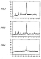
- Figure.2 is the X-ray diffraction pattern of the metallized, unleached electrode material of this invention, containing 41 weight percent aluminium, balance nickel, (see Example I below);
- Figure 3 is the X-ray diffraction pattern of an unleached, metallized electrode coating containing 53 weight percent aluminium, on an iron substrate, (see Example II below); and
- Figure 4 is the X-ray diffraction pattern of the metallized electrode shown in Figure 2, after leaching in 2 normal sodium hydroxide (see Example II below).
- In Figures 2 to 4 the X axis is "degrees two theta" and the Y axis is the intensity of the X-rays on the receiving instrument.
- Referring to Figure 1 of the drawings, an
arc 23 is struck between a pair of advancing metal wires 3,5. Thearc 23 melts the wires 3,5, thereby formingmolten metal particles 25. The molten metal particles 25'are carried.to theelectrode substrate 31 by ajet 21 of compressed air, and solidify to form a metallic film, coaating, layer, or surface on theelectrode substrate 31. - The wires 3, 5 are carried forward and continuously fed to the
arc 23. Typically, the wires 3, 5 are carried forward at a speed of from about 2 to about 10 inches per second by motor driven rollers. In this way an application rate of about 0.2 to about 3.0 pounds per minute is provided, although higher or lower application rates may be utilized. The spray can be moved laterally at a pitch of from about 0.125 inch to about 1 inch whereby to deposit metals at a loading of from about 5 x 10 -2 pounds per square foot to about 0.5 pounds of total metal per square foot. - The wires are generally from about 0.035 inch to about 0.16 inch in diameter., i.e., from about 16 gauge B. and S. to. about 5 gauge B. and S. As will be described more fully hereinbelow, the wires may be clad, e.g., with the catalytic metal as the inside, surrounded by a cladding of sacrificial metal.
- The electric power is sufficient to melt both wires. It is generally from about 3 kilowatts to about 24 kilowatts, i.e., from about 20 volts and 150 Amperes to about 40 volts and 600 amperes. In this way an arc temperature is provided that is hot enough to melt both the sacrificial metal and the catalytic metal, and to maintain the metals, including alloys and intermetallic compositions thereof, molten under conditions such as to form alloys, intermetallic compounds, and intimate mixtures thereof on the
electrode substrate 31. For nickel.and aluminium the proper temperature is above about 2000 degrees Centigrade, and up to about 2700 or 3000 degrees Centigrade. - The arc is generally spaced from about 0'.125 inch to about 1.00 inch from the electrode substrate. In this way fingered electrodes as described in e.g., U.S. Patent 3,968,021, may be coated, e.g., after fabrication, by inserting the metallizer 1 between the electrodes. The metallizer tips may be perpendicular to the electrode surface or at an angle with respect thereto.
- The molten metal is carried from the arc to the electrode substrate by compressed air. The compressed air carries the molten metal as a fine spray. The compressed air is preferably at a pressure above about 35 pounds per square inch, with pressures of about 50 to 75 pounds per square inch being particularly preferred.
- As herein contemplated, the two consumable wires 3, 5, e.g., wires of catalyst metal clad with sacrificial metal, are fed into the metallizer 1. Electrical current is transferred to the wires, e.g., through electrode tips, whereby to strike the
arc 23. Thearc 23 melts the wires 3, 5, formingmolten metal particles 25, which are propelled onto theelectrode substrate 31 by the-jet ofcompressed air 21. - According to one exemplification, at least one electro arc wire, e.g., wire 3 or wire 5, contains catalytic metal and at least one electro arc wire, e.g., either wire 5 or wire 3, contains sacrificial metal. According to a preferred exemplification, at least one of electro arc wires 3, 5 contains both catalytic metal and sacrificial metal, unalloyed with each other. According to a particularly preferred exemplification, both of the electro arc wires 3, 5 contain both catalytic metal and sacrificial metal unalloyed with each other.
- The catalytic metal and the sacrifical metal in the wires should be unalloyed because alloys of,<e.g., nickel and aluminium, are friable, non-malleable, and non-ductile. Even sintered wires of nickel and aluminium powders are not readily spoolable. According to one exemplification, the catalytic metal and the sacrificial metal may be braided or intertwined wires, i.e., wires consisting essentially of sacrificial metal twisted, braided, or intertwined with wires consisting essentially of catalytic wire. According to an alternative exemplification, the catalytic metal and the sacrificial metal may be a clad wire. In this way ease of wire feed to the arc is enhanced.
- The relative rates of catalytic metal to leachable or sacrificial metal are preferably such as to provide a surface of 35 to 80 percent porosity after deposition and leaching. This degree of porosity may be provided by a sacrificial metal content of about 30 to 80 percent by weight, basis total sacrificial metal and catalytic metal.
- While the catalytic metal is characterized as being a Group VIII transition, i.e., iron, cobalt, nickel, ruthenium, rhodium, palladium, osmium, iridium, or platinum, and especially nickel, it is to be understood that other transition metals may be present therewith. The other transition metals may be present with the catalytic metal at a trace level without deleterious effect. Alternatively, the other transition metals may be present therewith at a level sufficient to modify, enhance, or stabilize the catalytic properties, or to retard poisoning of the catalytic properties. The transition metal, other than a Group VIII transition metal, present in the porous, catalytic surface, may be molybdenum, titanium, tantalum, tungsten, niobium, or zirconium.
- The sacrificial metal, i.e., the leachable metal, is removed, whereby to yield a porous surface, film, coating or layer. The sacrificial metal may be removed by a strong acid or by a strong base.. Preferably it is removed by a strong base. Suitable strong bases are, for example, aqueous sodium hydroxide or aqueous potassium hydroxide.
- The leaching of the sacrificial metal may be carried out by means well known in the art, e.g., by immersion of the cathode in an alkaline medium prior to cell assembly, by immersion of the cathode in an alkaline medium during diaphragm deposition,by immersion of the diaphragm in an alkaline medium after cell assembly and prior to commencing electrolysis, by contacting the cathode with alkaline electrolyte during electrolysis, or by a combination of any of the above steps.
- The resulting porous surface, film, layer or coating has a porosity of preferably from about 35 to about 80 percent, and more preferably from about 50 to about 75 percent.
- As herein contemplated, the catalytic film, surface, or layer, adherent to the electroconductive substrate, is from about 0.001 inch thick to about 0.05 inch thick, i.e., from about 0.025 millimetres thick to about 1.25 millimetres thick, and contains from about 10 grams of catalytic metal per square foot to about 115 grams of catalytic metal per square foot, i.e., from about 23 to about 227 grams of total catalytic and sacrificial metal per square foot.
- The resulting porous surface, film, layer or coating may exhibit pyrophoric properties. That is, when exposed to air it may increase in temperature. Therefore, the activated cathode should be immersed in electrolyte, maintained under an inert gas, or coated with a protective film, e.g., a wax or polymeric film, when not in an electrolytic cell.
- The substrate is electroconductive and may be permeable to the flow of electrolyte between elements thereof, but substantially impermeable to the flow of electrolyte into the individual elements thereof. That is, the substrate is permeable to the bulk flow of electrolyte through individual elements thereof such as between individual rods or wires or through perforations, but not to the flow of electrolyte into and through the individual elements thereof. The cathode substrate may be, for example, a perforated sheet, a perforated plate, metal mesh, expanded metal mesh or metal rods.
- The substrate is typically an iron substrate. However, the electroconductive substrate may also be an electroconductive metal such as for example, aluminium, copper or lead, having an alkali-resistant surface thereon. Alternatively, the substrate can be cobalt, nickel, molybdenum, tungsten, or other alkali resistant metal. According to one particularly preferred exemplification, the electroconductive substrate has a nickel surface thereon whereby to protect the substrate from attack by concentrated alkali metal hydroxide catholyte liquors.
- The unleached surface, coating, layer or film, as metallized or electro arc deposited onto the electrode substrate, and the subsequent, leached, active, porous surface, coating, layer or film, may be characterized by their stoichiometry and X-ray diffraction pattern. For example, when the catalytic metal, i.e, the transition metal, is nickel, and the leachable metal, i.e., the sacrificial metal, is aluminium, the surface, as deposited, generally contains from about 37 to 67 weight percent aluminium, the balance consisting essentially of nickel. The resulting metallized surface has the nickel and aluminium present as Ni, NiAl3, Ni2Al3, and NiAl. Preferably a major portion of the aluminium and nickel are present as NiAl, NiAl3 and Ni2A13. The presence of Ni, NiAl3, Ni2Al3, and NiAl, if any, gives rise to a unique family of X-ray diffraction patterns.
- The observation of the X-ray diffraction pattern requires subjecting samples of powders of the surface coating, or even the coated electrode to X-rays from a copper target. This is accomplished as described in, for example, Chapter 5 of Klug and Alexander, X-Ray Diffraction Procedures, John Wiley and Sons, Inc., New York (1954), at pages 235-318, especially pages 270-318; and in Newfield, X-Ray Diffraction Methods, John Wiley and Sons, Inc., New York (1966) at pages 177-207.
- As described in these texts, X-rays have a wavelength of 1.5405 Angstom units. The X-rays diffracted by the sample are particularly intense at certain angles, theta, resulting in peaks on diffractometer printouts or in lines on photographic diffraction patterns. The high intensity peaks are caused by the X-rays being reflected from parallel planes in the crystal and reinforcing each other.
- The wavelength of the X-rays, the spacing of the planes in the crystal, and the angle, theta, are related by Bragg's Law:


- The X-ray diffraction data is obtained from a diffractometer that is direct reading in two theta, wherein 180 minus two theta is the angle between the incident ray and the reflected ray.
- The unleached metallized deposit of nickel and aluminium is characterized by five X-ray diffraction peaks. The highest peak is at 44 to 46 degrees two theta. Other peaks, in approximate order of prominence, are at 25.4 to 26 degrees two theta, 18 to 18.4 degrees two theta, and 65 to 66 degrees two theta. These peaks may be seen in the 53 weight percent aluminium electro- arc coating shown in Fig.3, and in the 41 weight percent aluminium electro-arc coating shown in Fig.2. To be noted is the greater number of components in the high aluminium content coating, Fig.3..To be noted in both unleached deposits is the strong nickel peak at 44 to 46 degrees two theta. This shows the segregation of nickel and aluminium, brought about by the disparity in melting points of the nickel, the aluminium, and the alloys.
- According to an exemplification of this invention, a 6 mesh to the inch by 6 mesh to the inch by 13 gauge steel screen is cleaned by sand-blasting. A pair of aluminium clad nickel wires, each containing an 0.035 inch diameter nickel wire surrounded by an 0.018 to 0.019 inch thick aluminium cladding are fed to a METCO 2R MINIARC metallizer. A potential of 20 to 40 volts is established between the two wires, and a sixty pound per square inch jet of compressed air drives the molten particles 0.25 to 0.75 inches to the substrate. The wire speed is-2 to 10 inches per second per wire, with the electro arc sprayer moving 2 to 10 inches per second, at a pitch of 0.125 inch to 1 inch. In this way a coverage rate of about 0.05 to 1.1 pounds per square foot may be provided. A deposit of about .008 to .025 inch thick is provided on the cathod substrate. Thereafter the coated substrate is activated in a one normal aqueous sodium hydroxide solution for 2 to 5 hours to remove the aluminium. A perfluorocarbon carboxylic acid ester permionic membrane is installed on the cathode, and the cathode-permionic membrane assembly is installed in an electrolytic cell. Electrolysis is commenced at a current density of 200-500 Amperes per square foot, and hydrogen is evolved at a hydrogen evolution overvoltage of 0.01 to 0.05 volt.
- The present'invention will now be further illustrated by way of the following Examples:
- A cathode was prepared by electro arc spraying nickel wire, clad with aluminium, onto a foraminous steel screen substrate. The cathode was then leached in aqueous sodium hydroxide. An asbestos diaphragm was applied to the leached cathode, and the cathode tested in a laboratory electrolytic cell.
- A 6 mesh to the inch by 6 mesh to the inch by 0.095 inch wire diameter (13 gauge), 8 inch by 10 inch, steel screen was degreased and.sandblasted. A nickel- aluminium coating was then electro arc sprayed onto one side of the steel screen substrate.
- The electro arc sprayed surface was applied by feeding two aluminium clad, nickel wires to a 200 ampere, 50 volt METCO 2R MINIARC metallizer. Each wire was approximately 0.063 inch in diameter with an 0.035 inch diameter nickel wire core surrounded by an aluminium cladding approximately 0.014 inch thick.
- A potential of 30 volts was imposed across the two wires, forming an arc and providing a current flow of 220 to 230 amperes. An air pressure of 65 pounds per square inch was applied at the arc. The spray angle was 90 degrees, and the spray distance was 0.75 inch, the wire speed was 4.6 inches per second and the electro arc sprayer was moved at 7.2 inches per second, providing a coverage rate of 0.32 pounds per square foot.
- A portion of the coating material was removed for X-ray diffraction study. The powder-sample had the X-ray diffraction pattern shown in Figure 2, evidencing A12Ni2, with the following peaks:


- The cathode was then etched in two normal aqueous sodium hydroxide at 24 degrees Centigrade for 3 hours. The surface appeared to be dark gray. A diaphragm was applied to the cathode by drawing a 2.09 weight percent slurry of mixed grades 3T and 4T chrysotile asbestos in an aqueous solution of about ten weight percent sodium'hydroxide and fifteen weight percent sodium chloride through the cathode. The cathode-diaphragm unit was then installed in a laboratory electrolysis cell and electrolysis was commenced. Over a period of 175 days of electrolysis the cathode voltage was below 1.19 volts versus a saturated calomel reference electrode, and the hydrogen overvoltage was below 0.08 volt.
- Three cathodes were prepared by electro arc spraying nickel wire, clad with aluminium, onto foraminous steel screen substrates. The cathodes were then leached in aqueous sodium hydroxide. A resin reinforced asbestos diaphragm was applied to each leached cathode, and the cathodes were tested in a laboratory electrolytic cell.
- Three 6 mesh to the inch by 6 mesh to the inch by 0.094 inch wire diameter, 8 inch by 10 inch, steel screens were degreased and sandblasted. A nickel- aluminium coating was then electro arc sprayed onto one side of each of the steel screen substrates. Electrodes D and E were 1 inch by 4 inch sections of the steel screen substrate.
- The electro arc sprayed surface was applied by feeding two aluminium clad, nickel wires to a METCO 2B MINIARC metallizer. Each wire was approximately 0.075 inch in diameter with an 0.035 inch diameter nickel wire core surrounded by an aluminium cladding approximately 0.020 inch thick.
- A potential of 30 volts was imposed across the two wires, forming an arc and providing a current flow of 220 to 230 amperes. An air pressure of 65 pounds per square inch was applied at the arc. The spray angle, distance between lines of movement of the electro arc sprayer, and the spray distance are shown in Table I, below. The wire speed was 5.6 inches per second, and the electro arc sprayer was moved at 5 inches per second.
- Each cathode was then etched in one normal aqueous sodium hydroxide at 24 degrees Centigrade for 3 hours. A diaphragm was applied to the cathode by drawing a 1.75 to 1.95 weight percent slurry of mixed grades 3T and 4T chrysotile asbestos in an aqueous solution of about ten weight percent sodium hydroxide and fifteen weight percent sodium chloride through the cathode. The cathode-diaphragm unit was then installed in a laboratory electrolysis cell and electrolysis was commenced. For electrodes A and'B the slurry contained 10 weight percent Allied Chemical Corporation HALAR® alternating poly(ethylene-chlorotrifluoroethylene), and the asbestos-diaphragm unit was heated to approximately 270 degrees for approximately 2 to 3 hours to melt the resin.
- The period of electrolysis, cathode voltage, and hydrogen overvoltage are shown in Table I, below.

- Electrode D was examined by X-ray diffraction before and after leaching in two normal aqueous sodium hydroxide. The unleached coating on the iron substrate had the X-ray diffraction pattern shown in Fig.3, evidencing Al3Ni2, Al3Ni, and the iron substrate, with the following peaks:
- 18.12 degrees two theta
- 22.00 degrees two theta
- 22.80 degrees two theta
- 24.12 degrees two theta
- 25.40 degrees two theta
- 25.90 degrees two theta
- 29.56 degrees two theta
- 31.30 degrees two theta
- 33.22 degrees two theta
- 35.10 degrees two theta
- 36.42 degrees two theta
- 37.28 degrees two theta
- 38.40 degrees two theta
- 39.17 degrees two theta
- 39.76 degrees two theta
- 41.16 degrees two theta
- 41.72 degrees two theta
- 43.58 degrees two theta
- 44.40 degrees two theta
- 44.82 degrees two theta
- 45.18 degrees two theta
- 46.00 degrees two theta
- 47.10 degrees two theta
- 48.34 degrees two theta
- 48.64 degrees two theta
- 49.50 degrees two theta
- 52.00 degrees two theta
- 55.40 degrees two theta
- 60.70 degrees two theta
- 62.82 degrees two theta
- 63.46 degrees two theta
- 65.10 degrees two theta
- 65.50 degrees two theta
- 68.40 degrees two theta
- 69;26 degrees two theta
- 71.20 degrees two theta
- 72.80 degrees two theta
- The leached coating on the iron substrate had the X-ray diffraction pattern shown in Fig.4 evidencing nickel, and the iron substrate, with the following peaks:
- 31.20 degrees two theta
- 44.66 degrees two theta
- 57.04 degrees two theta
- 51.62 degrees two theta
- 53.20 degrees two theta
- 64.80 degrees two theta
- While the invention has been described in terms of specific details, exemplifications, and embodiments thereof, the description is not intended to limit the invention, the scope of which is as defined in the claims appended thereto.
Claims (29)
Applications Claiming Priority (2)
| Application Number | Priority Date | Filing Date | Title |
|---|---|---|---|
| US258693 | 1981-04-29 | ||
| US06/258,693 US4396473A (en) | 1981-04-29 | 1981-04-29 | Cathode prepared by electro arc spray metallization, electro arc spray metallization method of preparing a cathode, and electrolysis with a cathode prepared by electro arc spray metallization |
Publications (2)
| Publication Number | Publication Date |
|---|---|
| EP0064840A1 true EP0064840A1 (en) | 1982-11-17 |
| EP0064840B1 EP0064840B1 (en) | 1986-08-27 |
Family
ID=22981730
Family Applications (1)
| Application Number | Title | Priority Date | Filing Date |
|---|---|---|---|
| EP82302200A Expired EP0064840B1 (en) | 1981-04-29 | 1982-04-29 | Electrode, method for its preparation and its use in electrolysis |
Country Status (5)
| Country | Link |
|---|---|
| US (1) | US4396473A (en) |
| EP (1) | EP0064840B1 (en) |
| JP (1) | JPS57181387A (en) |
| CA (1) | CA1208600A (en) |
| DE (1) | DE3272839D1 (en) |
Cited By (7)
| Publication number | Priority date | Publication date | Assignee | Title |
|---|---|---|---|---|
| EP0101423A3 (en) * | 1982-07-19 | 1985-04-10 | Energy Conversion Devices, Inc. | Fuel cell anode |
| EP0101421A3 (en) * | 1982-07-19 | 1985-04-17 | Energy Conversion Devices, Inc. | Fuel cell cathode |
| US4818741A (en) * | 1986-11-20 | 1989-04-04 | Electric Power Research Institute, Inc. | Porous and porous-nonporous composites for battery electrodes |
| EP0376730A3 (en) * | 1988-12-30 | 1990-10-17 | Westinghouse Electric Corporation | Method of fabricating titanium-aluminum shapes |
| WO1991000373A1 (en) * | 1989-06-29 | 1991-01-10 | Alcan International Limited | Manufacture of metallic alloys |
| EP0445353A1 (en) * | 1990-01-30 | 1991-09-11 | Air Products And Chemicals, Inc. | Electric arc spraying of reactive metals |
| WO1998037252A1 (en) * | 1997-02-24 | 1998-08-27 | Metallisation Limited | Metal spraying |
Families Citing this family (12)
| Publication number | Priority date | Publication date | Assignee | Title |
|---|---|---|---|---|
| CA1285782C (en) * | 1985-12-02 | 1991-07-09 | Peter Buus | Cylindrical freezing drum for slice ice making machines and a method of producing the drum |
| DE3629820A1 (en) * | 1985-09-05 | 1987-03-05 | Ppg Industries Inc | DIEPHRAGMA FROM SYNTHETIC POLYMERS, ITS PRODUCTION AND USE FOR CHLORINE ALKALINE ELECTROLYSIS |
| BR9200089A (en) * | 1992-01-03 | 1993-07-06 | Cofap | PISTON RING COATING PROCESS BY THERMAL ASPERSION |
| CA2103398C (en) * | 1992-11-19 | 2003-10-14 | Andrew T. C. Liu | Self-lubricating abrasion resistant material and products |
| TW383233B (en) * | 1995-01-31 | 2000-03-01 | Rieter Ag Maschf | Thread guiding elements |
| EP1693402A3 (en) | 1997-01-07 | 2009-05-27 | Kaneka Corporation | Cellulosic particles, spherical object comprising cross-linked polymer particles, and adsorbent for body fluid purification |
| US6258461B1 (en) * | 1999-03-12 | 2001-07-10 | Alloy Surfaces Co., Inc. | Activated nickel screens and foils |
| TWI269815B (en) * | 2002-05-20 | 2007-01-01 | Tosoh Smd Inc | Replaceable target sidewall insert with texturing |
| US20070278108A1 (en) * | 2006-06-01 | 2007-12-06 | General Electric Company | Method of forming a porous nickel coating, and related articles and compositions |
| DE102009051554A1 (en) * | 2009-10-31 | 2011-05-05 | Mtu Aero Engines Gmbh | Method for producing an inlet lining on a turbomachine |
| US8794540B2 (en) * | 2010-01-12 | 2014-08-05 | General Electric Company | Wire arc spray system using composite wire for porous coating, and related method |
| US8623501B2 (en) * | 2010-03-04 | 2014-01-07 | Basf Se | Lignocellulose materials having good mechanical properties |
Citations (5)
| Publication number | Priority date | Publication date | Assignee | Title |
|---|---|---|---|---|
| FR1068960A (en) * | 1951-11-22 | 1954-07-02 | Improvements in spray metallization processes | |
| FR1194596A (en) * | 1958-04-11 | 1959-11-10 | Metallisation De Prec | Advanced metallization process |
| DE1216648B (en) * | 1964-05-20 | 1966-05-12 | Heinrich Wilhelm Mueller | Metal spray wires for arc spraying |
| DE2002298A1 (en) * | 1970-01-20 | 1971-10-07 | Barthel Guenter Dipl Chem | Electrodes for water electrolysis |
| FR2323777A1 (en) * | 1975-09-15 | 1977-04-08 | Diamond Shamrock Corp | CATHODE FOR THE ELECTROLYSIS OF WATER OR AN AQUEOUS SOLUTION OF ALKALINE METAL HALOGENIDE |
Family Cites Families (8)
| Publication number | Priority date | Publication date | Assignee | Title |
|---|---|---|---|---|
| US3436248A (en) * | 1965-03-25 | 1969-04-01 | Metco Inc | Flame spraying exothermically reacting intermetallic compound forming composites |
| US3546415A (en) * | 1968-11-07 | 1970-12-08 | Flame Spray Ind Inc | Electric arc metallizing device |
| US3637437A (en) * | 1970-06-03 | 1972-01-25 | Catalytic Technology Corp | Raney metal sheet material |
| US4027367A (en) * | 1975-07-24 | 1977-06-07 | Rondeau Henry S | Spray bonding of nickel aluminum and nickel titanium alloys |
| US4049841A (en) * | 1975-09-08 | 1977-09-20 | Basf Wyandotte Corporation | Sprayed cathodes |
| US4116804A (en) * | 1976-11-17 | 1978-09-26 | E. I. Du Pont De Nemours And Company | Catalytically active porous nickel electrodes |
| GB1578889A (en) * | 1977-05-27 | 1980-11-12 | British Steel Corp | Surfacing circular-section metal members |
| US4230750A (en) * | 1979-08-15 | 1980-10-28 | Eutectic Corporation | Metallo-thermic powder |
-
1981
- 1981-04-29 US US06/258,693 patent/US4396473A/en not_active Expired - Fee Related
-
1982
- 1982-03-30 CA CA000399804A patent/CA1208600A/en not_active Expired
- 1982-04-20 JP JP57066191A patent/JPS57181387A/en active Pending
- 1982-04-29 DE DE8282302200T patent/DE3272839D1/en not_active Expired
- 1982-04-29 EP EP82302200A patent/EP0064840B1/en not_active Expired
Patent Citations (5)
| Publication number | Priority date | Publication date | Assignee | Title |
|---|---|---|---|---|
| FR1068960A (en) * | 1951-11-22 | 1954-07-02 | Improvements in spray metallization processes | |
| FR1194596A (en) * | 1958-04-11 | 1959-11-10 | Metallisation De Prec | Advanced metallization process |
| DE1216648B (en) * | 1964-05-20 | 1966-05-12 | Heinrich Wilhelm Mueller | Metal spray wires for arc spraying |
| DE2002298A1 (en) * | 1970-01-20 | 1971-10-07 | Barthel Guenter Dipl Chem | Electrodes for water electrolysis |
| FR2323777A1 (en) * | 1975-09-15 | 1977-04-08 | Diamond Shamrock Corp | CATHODE FOR THE ELECTROLYSIS OF WATER OR AN AQUEOUS SOLUTION OF ALKALINE METAL HALOGENIDE |
Non-Patent Citations (1)
| Title |
|---|
| PATENTS ABSTRACTS OF JAPAN, no. 63150R: "Fuel cell electrode" & JP-B-45 027306 (HITACHI)(07-09-1970) * |
Cited By (7)
| Publication number | Priority date | Publication date | Assignee | Title |
|---|---|---|---|---|
| EP0101423A3 (en) * | 1982-07-19 | 1985-04-10 | Energy Conversion Devices, Inc. | Fuel cell anode |
| EP0101421A3 (en) * | 1982-07-19 | 1985-04-17 | Energy Conversion Devices, Inc. | Fuel cell cathode |
| US4818741A (en) * | 1986-11-20 | 1989-04-04 | Electric Power Research Institute, Inc. | Porous and porous-nonporous composites for battery electrodes |
| EP0376730A3 (en) * | 1988-12-30 | 1990-10-17 | Westinghouse Electric Corporation | Method of fabricating titanium-aluminum shapes |
| WO1991000373A1 (en) * | 1989-06-29 | 1991-01-10 | Alcan International Limited | Manufacture of metallic alloys |
| EP0445353A1 (en) * | 1990-01-30 | 1991-09-11 | Air Products And Chemicals, Inc. | Electric arc spraying of reactive metals |
| WO1998037252A1 (en) * | 1997-02-24 | 1998-08-27 | Metallisation Limited | Metal spraying |
Also Published As
| Publication number | Publication date |
|---|---|
| DE3272839D1 (en) | 1986-10-02 |
| EP0064840B1 (en) | 1986-08-27 |
| US4396473A (en) | 1983-08-02 |
| JPS57181387A (en) | 1982-11-08 |
| CA1208600A (en) | 1986-07-29 |
Similar Documents
| Publication | Publication Date | Title |
|---|---|---|
| US4396473A (en) | Cathode prepared by electro arc spray metallization, electro arc spray metallization method of preparing a cathode, and electrolysis with a cathode prepared by electro arc spray metallization | |
| Couper et al. | Electrode materials for electrosynthesis | |
| US4248679A (en) | Electrolysis of alkali metal chloride in a cell having a nickel-molybdenum cathode | |
| US4116804A (en) | Catalytically active porous nickel electrodes | |
| US4169025A (en) | Process for making catalytically active Raney nickel electrodes | |
| US4323595A (en) | Nickel-molybdenum cathode | |
| US4414071A (en) | Electrode | |
| US4530742A (en) | Electrode and method of preparing same | |
| EP0163410B1 (en) | Electrolysis of halide-containing solutions with platinum based amorphous metal alloy anodes | |
| US4555317A (en) | Cathode for the electrolytic production of hydrogen and its use | |
| CA2575195A1 (en) | Apparatus for producing metal powder by electrowinning | |
| JPS62501219A (en) | Methods of manufacturing electrodes and their use in electrochemical processes | |
| EP0031948B1 (en) | A hydrogen-evolution electrode | |
| EP0804636A1 (en) | Cathode for use in electrolytic cell | |
| US4007107A (en) | Electrolytic anode | |
| US4240895A (en) | Raney alloy coated cathode for chlor-alkali cells | |
| EP0129734B1 (en) | Preparation and use of electrodes | |
| US4370361A (en) | Process of forming Raney alloy coated cathode for chlor-alkali cells | |
| CA2387563A1 (en) | Catalytic powder and electrode made therewith | |
| US4518457A (en) | Raney alloy coated cathode for chlor-alkali cells | |
| JP2584778B2 (en) | Cathode suitable for use in electrochemical processes that generate hydrogen | |
| US4331517A (en) | Method of preparing a cathode by high and low temperature electroplating of catalytic and sacrificial metals, and electrode prepared thereby | |
| GB2074190A (en) | Improved Electrode | |
| US4055477A (en) | Electrolyzing brine using an anode coated with an intermetallic compound | |
| CA1260427A (en) | Low hydrogen overvoltage cathode and method for producing the same |
Legal Events
| Date | Code | Title | Description |
|---|---|---|---|
| PUAI | Public reference made under article 153(3) epc to a published international application that has entered the european phase |
Free format text: ORIGINAL CODE: 0009012 |
|
| 17P | Request for examination filed |
Effective date: 19820505 |
|
| AK | Designated contracting states |
Designated state(s): BE DE FR GB IT NL SE |
|
| RAP1 | Party data changed (applicant data changed or rights of an application transferred) |
Owner name: PPG INDUSTRIES, INC. |
|
| GRAA | (expected) grant |
Free format text: ORIGINAL CODE: 0009210 |
|
| AK | Designated contracting states |
Kind code of ref document: B1 Designated state(s): BE DE FR GB IT NL SE |
|
| ITF | It: translation for a ep patent filed | ||
| REF | Corresponds to: |
Ref document number: 3272839 Country of ref document: DE Date of ref document: 19861002 |
|
| ET | Fr: translation filed | ||
| PLBE | No opposition filed within time limit |
Free format text: ORIGINAL CODE: 0009261 |
|
| STAA | Information on the status of an ep patent application or granted ep patent |
Free format text: STATUS: NO OPPOSITION FILED WITHIN TIME LIMIT |
|
| 26N | No opposition filed | ||
| PGFP | Annual fee paid to national office [announced via postgrant information from national office to epo] |
Ref country code: FR Payment date: 19900307 Year of fee payment: 9 |
|
| PGFP | Annual fee paid to national office [announced via postgrant information from national office to epo] |
Ref country code: SE Payment date: 19900313 Year of fee payment: 9 Ref country code: DE Payment date: 19900313 Year of fee payment: 9 |
|
| PGFP | Annual fee paid to national office [announced via postgrant information from national office to epo] |
Ref country code: BE Payment date: 19900315 Year of fee payment: 9 |
|
| PGFP | Annual fee paid to national office [announced via postgrant information from national office to epo] |
Ref country code: GB Payment date: 19900331 Year of fee payment: 9 |
|
| ITTA | It: last paid annual fee | ||
| PGFP | Annual fee paid to national office [announced via postgrant information from national office to epo] |
Ref country code: NL Payment date: 19900430 Year of fee payment: 9 |
|
| PG25 | Lapsed in a contracting state [announced via postgrant information from national office to epo] |
Ref country code: GB Effective date: 19910429 |
|
| PG25 | Lapsed in a contracting state [announced via postgrant information from national office to epo] |
Ref country code: SE Effective date: 19910430 Ref country code: BE Effective date: 19910430 |
|
| BERE | Be: lapsed |
Owner name: PPG INDUSTRIES INC. Effective date: 19910430 |
|
| PG25 | Lapsed in a contracting state [announced via postgrant information from national office to epo] |
Ref country code: NL Effective date: 19911101 |
|
| NLV4 | Nl: lapsed or anulled due to non-payment of the annual fee | ||
| PG25 | Lapsed in a contracting state [announced via postgrant information from national office to epo] |
Ref country code: FR Effective date: 19911230 |
|
| GBPC | Gb: european patent ceased through non-payment of renewal fee | ||
| PG25 | Lapsed in a contracting state [announced via postgrant information from national office to epo] |
Ref country code: DE Effective date: 19920201 |
|
| REG | Reference to a national code |
Ref country code: FR Ref legal event code: ST |
|
| EUG | Se: european patent has lapsed |
Ref document number: 82302200.9 Effective date: 19911108 |