EP0064334B1 - Temperature surveillance system - Google Patents
Temperature surveillance system Download PDFInfo
- Publication number
- EP0064334B1 EP0064334B1 EP82301841A EP82301841A EP0064334B1 EP 0064334 B1 EP0064334 B1 EP 0064334B1 EP 82301841 A EP82301841 A EP 82301841A EP 82301841 A EP82301841 A EP 82301841A EP 0064334 B1 EP0064334 B1 EP 0064334B1
- Authority
- EP
- European Patent Office
- Prior art keywords
- junctions
- disposed
- cables
- temperature
- polarity
- Prior art date
- Legal status (The legal status is an assumption and is not a legal conclusion. Google has not performed a legal analysis and makes no representation as to the accuracy of the status listed.)
- Expired
Links
Images

Classifications
-
- G—PHYSICS
- G01—MEASURING; TESTING
- G01K—MEASURING TEMPERATURE; MEASURING QUANTITY OF HEAT; THERMALLY-SENSITIVE ELEMENTS NOT OTHERWISE PROVIDED FOR
- G01K1/00—Details of thermometers not specially adapted for particular types of thermometer
- G01K1/02—Means for indicating or recording specially adapted for thermometers
- G01K1/026—Means for indicating or recording specially adapted for thermometers arrangements for monitoring a plurality of temperatures, e.g. by multiplexing
-
- G—PHYSICS
- G01—MEASURING; TESTING
- G01K—MEASURING TEMPERATURE; MEASURING QUANTITY OF HEAT; THERMALLY-SENSITIVE ELEMENTS NOT OTHERWISE PROVIDED FOR
- G01K3/00—Thermometers giving results other than momentary value of temperature
- G01K3/08—Thermometers giving results other than momentary value of temperature giving differences of values; giving differentiated values
- G01K3/14—Thermometers giving results other than momentary value of temperature giving differences of values; giving differentiated values in respect of space
-
- G—PHYSICS
- G01—MEASURING; TESTING
- G01K—MEASURING TEMPERATURE; MEASURING QUANTITY OF HEAT; THERMALLY-SENSITIVE ELEMENTS NOT OTHERWISE PROVIDED FOR
- G01K7/00—Measuring temperature based on the use of electric or magnetic elements directly sensitive to heat ; Power supply therefor, e.g. using thermoelectric elements
- G01K7/02—Measuring temperature based on the use of electric or magnetic elements directly sensitive to heat ; Power supply therefor, e.g. using thermoelectric elements using thermoelectric elements, e.g. thermocouples
Definitions
- This invention relates to temperature surveillance systems for structures such as vessels.
- structures which operate normally at a uniformly distributed constant temperature, it is desirable to have means for detecting a fault condition causing a localised change in temperature.
- a typical example of such a structure is a containment vessel for the reactor core of a nuclear installation.
- a thermal carrier is provided between the reactor core and the vessel and it is desirable to be warned of a breakdown in the barrier.
- regions of the structure which are susceptible to fault conditions which give rise to a localised temperature increase are each monitored by means of a discrete thermocouple hot junction.
- the junction can conveniently be formed at the end of a length of metal sheathed mineral insulated cable by welding ends of a pair of conductors together and closing the end of the sheath by capping. Difficulties arise in that such a system calls for a large number of cables which increases the possibility of a faulty signal and imposes the need for a large number of penetration glands in the vessel.
- a core of a nuclear reactor has an equal number of nuclear fuel assemblies and temperature sensing instruments arranged in parallel array.
- Each temperature sensing instrument has three thermocouple hot junctions connected in series with each hot junction being disposed to monitor coolant flow from a respective fuel assembly.
- Each temperature sensing instrument therefore, senses coolant flow from three fuel assemblies, and each fuel assembly is sensed by three sensing instruments.
- Such an arrangement provides for redundancy of up to two or three instruments, but there is a reduction in location sensitivity.
- the system also requires the use of complex interrogation processes.
- An object of the invention is to provide a temperature surveillance system which is robust and capable of monitoring as many points as a given system of the described conventional kind with fewer cables.
- a temperature surveillance system comprising a plurality of metal sheathed mineral insulated cables, each cable having a co-axial conductor comprising alternate lengths of dissimilar materials which provide thermo-electric junctions, alternately of opposite polarity, at their end abutments, is characterised in that the cables are disposed in a lattice array, the cables being arranged so that like junctions of one polarity are stationed at the intersection of the cables in the lattice array whilst the junctions of opposite polarity are disposed between the intersections.
- sensing junctions When the system is disposed over a structure such that the like junctions at the intersections of the cables in the lattice array, hereinafter referred to as sensing junctions, are disposed at points of the structure susceptible to fault conditions whilst the remaining junctions of opposite polarity, hereinafter referred to as reference junctions, are disposed at substantially isothermal points of the structure, a fault condition giving rise to increased temperature produces a detectable change in emf in the cables whereby the fault condition can be detected and located.
- Co-axial metal sheathed mineral insulated cables provide a surveillance system of greater integrity than the conventional system because for a given cross-sectional area of cable the insulant thicknesses can be reduced enabling the use of a more robust sheath of greater wall thickness and a conductor of larger cross section.
- the coaxial geometry substantially ensures that no undisclosed fault can exist.
- the temperature surveillance system comprises a plurality of cables each comprising a single conductor disposed co-axially within a tubular metal sheath and insulated therefrom by powdered mineral insulation.
- the sheath may be of stainless steel and the insulation of magnesium oxide.
- the conductors each comprise alternate lengths of dissimilar thermo-electric material, for example, Nickel-Chromium alloy and Nickel-Aluminium alloy designated A and B respectively in Figure 1.
- the end abutments provide thermo-electric junctions, alternate junctions being of opposite polarity.
- T 1 and T 2 the two terminal lengths of conductors designated T 1 and T 2 , are of the same material and a complete cable is maintained isothermal between T 1 and T 2 , then there will be no thermo-electric output but when any single junction region experiences a change of temperature, 8, an emf E8 will be established between T 1 and T 2 .
- E8 will be a function of the temperature change and the thermo-electric power of the materials A and B.
- the polarity of the emf will depend upon whether a positive or negative gradient junction is effected and whether the temperature increases or decreases. If "n" common polarity junctions experience the same change, 8, the emf produced becomes nE8.
- the arrangement shown in Figure 2 comprises a plurality of the cable shown diagrammatically in Figure 1 arranged in a notional lattice array the co-ordinates being designated X, Y with suffixes a, b, c and d.
- the cables are arranged so that like thermo-junctions of one polarity (designated +ve in Figure 2) are stationed at the intersections of the lattice array whilst the junctions of opposite polarity (designated -ve in Figure 2) are disposed between the intersections.
- the temperature surveillance system is attached to a structure such that the junctions of positive polarity are disposed at regions of the structure susceptible to fault conditions which can cause a temperature change whilst the negative junctions are disposed at regions which are maintained at a temperature which is average for the structure.
- the change in temperature gives rise to a representative thermo-electric signal which gives an indication of the existence of a thermal fault.
- the described system represents an ideal lattice arrangement but in a practical application the reference junctions can be thermally coupled to any constant temperature position which is independent of the fault phenomena and the standing potential existing on each cable will have to be disregarded when interrogating the system for fault signals.
- the adjacent sensing and reference junctions designated 1 and 2 respectively are placed either side of a thermal barrier element 3 which is itself attached to the structure 4 at the critical location.
- the thermal barrier element may be, for example, gas pocket defining sheets of stainless steel or ceramic bricks.
- the reference thermal junctions 2 are enclosed in a mass 5 of material of low thermal diffusivity and then attached to the same part of the structure 4 as the sensing junction 1. Any fault which causes a change in the output of the sensing junction will be delayed in its influence on the reference junction for a period of time which may be several minutes. During this time delay, an interrogation system will be able to identify a faulty station.
- the material of low thermal diffusivity may be for example, a glass fiber mat.
- the main advantage of the described temperature surveillance system is that fewer cables are required than in a system where a single conventional thermocouple is placed at each station, and interrogation is less complex than in the systems described in United States patent No. 3922192 and French Patent No. 2315689.
- a cable lattice with a 10 x 10 distribution, for example, will monitor 100 stations at the cost of only 20 cables.
- Further advantages reside in the fact that co-axial thermocouples being of high integrity reduce the risk of spurious faults, particularly since undisclosed faults cannot be sustained by a co-axial thermocouple and replacement of a faulty cable due, for example, to conductor or insulation faults can be effected by using the original cable as a draw-wire to insert a replacement.
Landscapes
- Physics & Mathematics (AREA)
- General Physics & Mathematics (AREA)
- Monitoring And Testing Of Nuclear Reactors (AREA)
- Measuring Temperature Or Quantity Of Heat (AREA)
- Fire-Detection Mechanisms (AREA)
- Emergency Alarm Devices (AREA)
Description
- This invention relates to temperature surveillance systems for structures such as vessels. In some structures which operate normally at a uniformly distributed constant temperature, it is desirable to have means for detecting a fault condition causing a localised change in temperature. A typical example of such a structure is a containment vessel for the reactor core of a nuclear installation. A thermal carrier is provided between the reactor core and the vessel and it is desirable to be warned of a breakdown in the barrier. In a conventional temperature surveillance system regions of the structure which are susceptible to fault conditions which give rise to a localised temperature increase are each monitored by means of a discrete thermocouple hot junction. The junction can conveniently be formed at the end of a length of metal sheathed mineral insulated cable by welding ends of a pair of conductors together and closing the end of the sheath by capping. Difficulties arise in that such a system calls for a large number of cables which increases the possibility of a faulty signal and imposes the need for a large number of penetration glands in the vessel.
- In another temperature surveillance system described in United States Patent Specification No. 3922192, a core of a nuclear reactor has an equal number of nuclear fuel assemblies and temperature sensing instruments arranged in parallel array. Each temperature sensing instrument has three thermocouple hot junctions connected in series with each hot junction being disposed to monitor coolant flow from a respective fuel assembly. Each temperature sensing instrument therefore, senses coolant flow from three fuel assemblies, and each fuel assembly is sensed by three sensing instruments. Such an arrangement provides for redundancy of up to two or three instruments, but there is a reduction in location sensitivity. The system also requires the use of complex interrogation processes.
- In French patent No. 2315689, a grid of two kinds of metallic conductors is arranged in which each conductor of one kind crosses all the conductors of the other kind and is welded thereto to form thermo-electric hot junctions at the intersections, each conductor being connected to external isothermal terminals. However, in order to establish the location of a temperature rise with such an arrangement complex interrogation techniques are necessary.
- An object of the invention is to provide a temperature surveillance system which is robust and capable of monitoring as many points as a given system of the described conventional kind with fewer cables.
- According to the invention, a temperature surveillance system comprising a plurality of metal sheathed mineral insulated cables, each cable having a co-axial conductor comprising alternate lengths of dissimilar materials which provide thermo-electric junctions, alternately of opposite polarity, at their end abutments, is characterised in that the cables are disposed in a lattice array, the cables being arranged so that like junctions of one polarity are stationed at the intersection of the cables in the lattice array whilst the junctions of opposite polarity are disposed between the intersections.
- When the system is disposed over a structure such that the like junctions at the intersections of the cables in the lattice array, hereinafter referred to as sensing junctions, are disposed at points of the structure susceptible to fault conditions whilst the remaining junctions of opposite polarity, hereinafter referred to as reference junctions, are disposed at substantially isothermal points of the structure, a fault condition giving rise to increased temperature produces a detectable change in emf in the cables whereby the fault condition can be detected and located. Co-axial metal sheathed mineral insulated cables provide a surveillance system of greater integrity than the conventional system because for a given cross-sectional area of cable the insulant thicknesses can be reduced enabling the use of a more robust sheath of greater wall thickness and a conductor of larger cross section. The coaxial geometry substantially ensures that no undisclosed fault can exist.
- A temperature surveillance system embodying the invention is described, by way of example, with reference to the accompanying diagrammatic drawings wherein:
- Figure 1 shows the thermo-junction distribution in a metal sheathed mineral insulated cable for use in the system.
- Figure 2 shows a lattice arrangement of cables of the kind shown in Figure 1, and
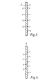
- Figures 3 and 4 are sectional side views showing alternative structures.
- The temperature surveillance system comprises a plurality of cables each comprising a single conductor disposed co-axially within a tubular metal sheath and insulated therefrom by powdered mineral insulation. Typically, the sheath may be of stainless steel and the insulation of magnesium oxide. The conductors each comprise alternate lengths of dissimilar thermo-electric material, for example, Nickel-Chromium alloy and Nickel-Aluminium alloy designated A and B respectively in Figure 1. The end abutments provide thermo-electric junctions, alternate junctions being of opposite polarity. With reference to Figure 1, if the two terminal lengths of conductors designated T1 and T2, are of the same material and a complete cable is maintained isothermal between T1 and T2, then there will be no thermo-electric output but when any single junction region experiences a change of temperature, 8, an emf E8 will be established between T1 and T2. E8 will be a function of the temperature change and the thermo-electric power of the materials A and B. The polarity of the emf will depend upon whether a positive or negative gradient junction is effected and whether the temperature increases or decreases. If "n" common polarity junctions experience the same change, 8, the emf produced becomes nE8.
- The arrangement shown in Figure 2 comprises a plurality of the cable shown diagrammatically in Figure 1 arranged in a notional lattice array the co-ordinates being designated X, Y with suffixes a, b, c and d. The cables are arranged so that like thermo-junctions of one polarity (designated +ve in Figure 2) are stationed at the intersections of the lattice array whilst the junctions of opposite polarity (designated -ve in Figure 2) are disposed between the intersections.
- In use, the temperature surveillance system is attached to a structure such that the junctions of positive polarity are disposed at regions of the structure susceptible to fault conditions which can cause a temperature change whilst the negative junctions are disposed at regions which are maintained at a temperature which is average for the structure. In the event of a fault condition, the change in temperature gives rise to a representative thermo-electric signal which gives an indication of the existence of a thermal fault.
- The principle is valid for multiple faults since only cables having junctions coincident with a faulty station will carry a signal. Two examples of a double fault condition are described with reference to Figure 2. If there are faults at stations bb and bc, signals will be observed on cables Xb, Xc and Yb. If there are faults at stations bb and bd signals will be observed on cables Xb, Xd and Yb. In both cases the Yb signal will be twice the representative amplitude (2E8) confirming that it is responding to two fault stations.
- The described system represents an ideal lattice arrangement but in a practical application the reference junctions can be thermally coupled to any constant temperature position which is independent of the fault phenomena and the standing potential existing on each cable will have to be disregarded when interrogating the system for fault signals.
- In an alternative application shown in Figure 3, the adjacent sensing and reference junctions designated 1 and 2 respectively, are placed either side of a
thermal barrier element 3 which is itself attached to thestructure 4 at the critical location. This will produce a change in thermal emf when, for example, loss of insulation causes an increase in the heat flow designated F across the thermal barrier. The thermal barrier element may be, for example, gas pocket defining sheets of stainless steel or ceramic bricks. - In a further alternative application shown in Figure 4 the reference
thermal junctions 2 are enclosed in amass 5 of material of low thermal diffusivity and then attached to the same part of thestructure 4 as thesensing junction 1. Any fault which causes a change in the output of the sensing junction will be delayed in its influence on the reference junction for a period of time which may be several minutes. During this time delay, an interrogation system will be able to identify a faulty station. The material of low thermal diffusivity, may be for example, a glass fiber mat. - The main advantage of the described temperature surveillance system is that fewer cables are required than in a system where a single conventional thermocouple is placed at each station, and interrogation is less complex than in the systems described in United States patent No. 3922192 and French Patent No. 2315689. A cable lattice with a 10 x 10 distribution, for example, will monitor 100 stations at the cost of only 20 cables. Further advantages reside in the fact that co-axial thermocouples being of high integrity reduce the risk of spurious faults, particularly since undisclosed faults cannot be sustained by a co-axial thermocouple and replacement of a faulty cable due, for example, to conductor or insulation faults can be effected by using the original cable as a draw-wire to insert a replacement.
Claims (5)
Applications Claiming Priority (2)
| Application Number | Priority Date | Filing Date | Title |
|---|---|---|---|
| GB8112045 | 1981-04-16 | ||
| GB8112045 | 1981-04-16 |
Publications (3)
| Publication Number | Publication Date |
|---|---|
| EP0064334A2 EP0064334A2 (en) | 1982-11-10 |
| EP0064334A3 EP0064334A3 (en) | 1983-11-30 |
| EP0064334B1 true EP0064334B1 (en) | 1986-09-24 |
Family
ID=10521207
Family Applications (1)
| Application Number | Title | Priority Date | Filing Date |
|---|---|---|---|
| EP82301841A Expired EP0064334B1 (en) | 1981-04-16 | 1982-04-07 | Temperature surveillance system |
Country Status (4)
| Country | Link |
|---|---|
| US (1) | US4488269A (en) |
| EP (1) | EP0064334B1 (en) |
| JP (1) | JPS581292A (en) |
| DE (1) | DE3273407D1 (en) |
Families Citing this family (18)
| Publication number | Priority date | Publication date | Assignee | Title |
|---|---|---|---|---|
| GB8511051D0 (en) * | 1985-05-01 | 1985-06-12 | Bicc Plc | Mineral insulated thermocouple cable |
| CA1289268C (en) * | 1988-11-21 | 1991-09-17 | Harald H. Schmidt | Thermocouple with bent sheath |
| GB2291197B (en) * | 1994-06-23 | 1998-10-28 | Alan Keith Wood | Two/three dimensional temperature sensor |
| DE4435959C2 (en) * | 1994-10-07 | 1997-09-04 | Goodwell Int Ltd | Snowboard boots |
| US6180867B1 (en) | 1996-04-17 | 2001-01-30 | General Electric Company | Thermal sensor array and methods of fabrication and use |
| US5909004A (en) * | 1996-04-17 | 1999-06-01 | General Electric Company | Thermocouple array and method of fabrication |
| US6137669A (en) * | 1998-10-28 | 2000-10-24 | Chiang; Justin N. | Sensor |
| US7394060B2 (en) * | 2004-05-03 | 2008-07-01 | Tamperproof Container Licensing Corp. | Tamper detection system having plurality of inflatable liner panels with optical couplers |
| US7332728B2 (en) * | 2004-11-05 | 2008-02-19 | Tamperproof Container Licensing Corp. | Tamper-proof container |
| US7482924B1 (en) | 2004-11-05 | 2009-01-27 | Tamper Proof Container Licensing Corp. | Cargo container security system communications |
| US7608812B2 (en) * | 2004-11-05 | 2009-10-27 | Tamperproof Container Licensing Corp. | Tamper detection system |
| DE102006019578A1 (en) * | 2006-04-27 | 2007-10-31 | Abb Patent Gmbh | Gas or air temperature measurement device for use in low-voltage switching cabinet, has several temperature sensors that are fixed to places, which are arranged in matrix-shape, in evenly distributed manner and arranged above housing |
| US7619226B2 (en) * | 2007-03-30 | 2009-11-17 | Tamper Proof Container Licensing Corp. | Integrated optical neutron detector |
| WO2009075703A2 (en) * | 2007-09-11 | 2009-06-18 | Tamper Proof Container Licensing Corp. | Pipeline security system |
| US7924166B2 (en) * | 2009-05-18 | 2011-04-12 | Tamperproof Container Licensing Corp. | Nuclear leakage detection system using wire or optical fiber |
| US8653971B2 (en) | 2012-01-25 | 2014-02-18 | 3D Fuse Sarl | Sensor tape for security detection and method of fabrication |
| US8971673B2 (en) | 2012-01-25 | 2015-03-03 | 3D Fuse Sarl | Sensor tape for security detection and method of fabrication |
| US9373234B1 (en) | 2015-01-20 | 2016-06-21 | 3D Fuse Technology Inc. | Security tape for intrusion/extrusion boundary detection |
Citations (1)
| Publication number | Priority date | Publication date | Assignee | Title |
|---|---|---|---|---|
| US3922192A (en) * | 1972-11-01 | 1975-11-25 | Atomic Energy Authority Uk | Nuclear reactor instrumentation |
Family Cites Families (9)
| Publication number | Priority date | Publication date | Assignee | Title |
|---|---|---|---|---|
| GB922572A (en) * | 1960-10-10 | 1963-04-03 | Parsons C A & Co Ltd | Improvements in and relating to nuclear reactors |
| FR1406368A (en) * | 1964-09-02 | 1965-07-16 | Atomic Energy Authority Uk | Temperature tracking process |
| US3715441A (en) * | 1971-07-26 | 1973-02-06 | H Collins | Induction furnace with thermocouple assembly |
| US3911727A (en) * | 1973-03-02 | 1975-10-14 | Mitsubishi Heavy Ind Ltd | Thermal leak detector for a heat-insulation-lined tank for low-temperature liquids |
| FR2251935A1 (en) * | 1973-11-16 | 1975-06-13 | Commissariat Energie Atomique | High temtemperature thermopile - using series connected tungsten-rhenium alloy junctions |
| US4037463A (en) * | 1974-07-10 | 1977-07-26 | Showa Denko Kabushiki Kaisha | Temperature-detecting element |
| FR2315689A1 (en) * | 1975-06-25 | 1977-01-21 | Anvar | Temp. measuring conductor network - uses thermoelectric effect at crossing points of conducting strips of two different materials |
| US4162175A (en) * | 1976-08-18 | 1979-07-24 | United Kingdom Atomic Energy Authority | Temperature sensors |
| US4242907A (en) * | 1979-02-12 | 1981-01-06 | Kazmierowicz Casimir W | Apparatus for monitoring and controlling a flat zone in a furnace |
-
1982
- 1982-04-07 EP EP82301841A patent/EP0064334B1/en not_active Expired
- 1982-04-07 DE DE8282301841T patent/DE3273407D1/en not_active Expired
- 1982-04-09 US US06/367,064 patent/US4488269A/en not_active Expired - Fee Related
- 1982-04-16 JP JP57063795A patent/JPS581292A/en active Granted
Patent Citations (1)
| Publication number | Priority date | Publication date | Assignee | Title |
|---|---|---|---|---|
| US3922192A (en) * | 1972-11-01 | 1975-11-25 | Atomic Energy Authority Uk | Nuclear reactor instrumentation |
Also Published As
| Publication number | Publication date |
|---|---|
| EP0064334A3 (en) | 1983-11-30 |
| DE3273407D1 (en) | 1986-10-30 |
| EP0064334A2 (en) | 1982-11-10 |
| US4488269A (en) | 1984-12-11 |
| JPS6356599B2 (en) | 1988-11-08 |
| JPS581292A (en) | 1983-01-06 |
Similar Documents
| Publication | Publication Date | Title |
|---|---|---|
| US4488269A (en) | Temperature surveillance systems | |
| US4483631A (en) | Multiple thermocouple system for high temperature reactors | |
| US9835497B2 (en) | Rod thermometer device for detecting a temperature, use for the electrical simulation of nuclear fuel rods | |
| US4418035A (en) | Coolant condition monitor for nuclear power reactor | |
| US4603580A (en) | Unicable liquid level sensing system | |
| EP0294691B1 (en) | Resistance temperature detector | |
| EP0153607A2 (en) | Multi-wire mineral insulated cable thermocouple reference junction | |
| US5712886A (en) | Device for detecting and monitoring perforation of the bottom head of the vessel of a nuclear reactor | |
| US5171517A (en) | Method for monitoring corrosion on a member in a nuclear reactor core | |
| US4350968A (en) | Liquid level detector | |
| EP0157132B1 (en) | Reactor monitoring assembly | |
| US4725399A (en) | Probe with integrated heater and thermocouple pack | |
| US4449413A (en) | Extensometers | |
| EP0490163A1 (en) | Sensor and method for monitoring corrosion on a member in a nuclear reactor core | |
| JP3028941B2 (en) | Multi-sheath type sodium leak detection device | |
| EP0263226B1 (en) | A method and an instrument for monitoring the cooling conditions in a light water reactor | |
| JPH07193986A (en) | Power cable connection monitoring method | |
| JP2003057120A (en) | Multi-point temperature measuring device | |
| US3418207A (en) | System for functional supervision of heat-insulating layers in nuclear reactor channels | |
| US4780272A (en) | Device for suspending a structure | |
| CN212847046U (en) | Wide-width netted fire detector | |
| JPH0617833B2 (en) | Temperature detector | |
| JPH0738865Y2 (en) | Gas insulation switchgear abnormality monitoring device | |
| SU1236527A1 (en) | Method of detecting fire | |
| JPH01185487A (en) | Method and apparatus for monitoring cooling state of light water reactor |
Legal Events
| Date | Code | Title | Description |
|---|---|---|---|
| PUAI | Public reference made under article 153(3) epc to a published international application that has entered the european phase |
Free format text: ORIGINAL CODE: 0009012 |
|
| AK | Designated contracting states |
Designated state(s): DE FR GB IT |
|
| PUAL | Search report despatched |
Free format text: ORIGINAL CODE: 0009013 |
|
| AK | Designated contracting states |
Designated state(s): DE FR GB IT |
|
| 17P | Request for examination filed |
Effective date: 19840121 |
|
| GRAA | (expected) grant |
Free format text: ORIGINAL CODE: 0009210 |
|
| AK | Designated contracting states |
Kind code of ref document: B1 Designated state(s): DE FR GB IT |
|
| ITF | It: translation for a ep patent filed | ||
| REF | Corresponds to: |
Ref document number: 3273407 Country of ref document: DE Date of ref document: 19861030 |
|
| ET | Fr: translation filed | ||
| PLBE | No opposition filed within time limit |
Free format text: ORIGINAL CODE: 0009261 |
|
| STAA | Information on the status of an ep patent application or granted ep patent |
Free format text: STATUS: NO OPPOSITION FILED WITHIN TIME LIMIT |
|
| 26N | No opposition filed | ||
| ITTA | It: last paid annual fee | ||
| PGFP | Annual fee paid to national office [announced via postgrant information from national office to epo] |
Ref country code: DE Payment date: 19910319 Year of fee payment: 10 |
|
| PGFP | Annual fee paid to national office [announced via postgrant information from national office to epo] |
Ref country code: GB Payment date: 19910320 Year of fee payment: 10 |
|
| PGFP | Annual fee paid to national office [announced via postgrant information from national office to epo] |
Ref country code: FR Payment date: 19910325 Year of fee payment: 10 |
|
| PG25 | Lapsed in a contracting state [announced via postgrant information from national office to epo] |
Ref country code: GB Effective date: 19920407 |
|
| GBPC | Gb: european patent ceased through non-payment of renewal fee | ||
| PG25 | Lapsed in a contracting state [announced via postgrant information from national office to epo] |
Ref country code: FR Effective date: 19921230 |
|
| PG25 | Lapsed in a contracting state [announced via postgrant information from national office to epo] |
Ref country code: DE Effective date: 19930101 |
|
| REG | Reference to a national code |
Ref country code: FR Ref legal event code: ST |