EP0064168B1 - Jitter compensated scene stabilized missile guidance system - Google Patents
Jitter compensated scene stabilized missile guidance system Download PDFInfo
- Publication number
- EP0064168B1 EP0064168B1 EP82102966A EP82102966A EP0064168B1 EP 0064168 B1 EP0064168 B1 EP 0064168B1 EP 82102966 A EP82102966 A EP 82102966A EP 82102966 A EP82102966 A EP 82102966A EP 0064168 B1 EP0064168 B1 EP 0064168B1
- Authority
- EP
- European Patent Office
- Prior art keywords
- signals
- tracking
- successive frames
- jitter
- motion
- Prior art date
- Legal status (The legal status is an assumption and is not a legal conclusion. Google has not performed a legal analysis and makes no representation as to the accuracy of the status listed.)
- Expired
Links
Images
Classifications
-
- F—MECHANICAL ENGINEERING; LIGHTING; HEATING; WEAPONS; BLASTING
- F41—WEAPONS
- F41G—WEAPON SIGHTS; AIMING
- F41G7/00—Direction control systems for self-propelled missiles
- F41G7/20—Direction control systems for self-propelled missiles based on continuous observation of target position
- F41G7/30—Command link guidance systems
Definitions
- This invention relates to a line-of-sight commanded missile guidance system according to the preamble of Claim 1.
- a typical line-of-sight commanded missile system as disclosed in US-A-3 885 453 and US-A-4 247 059 includes a launcher and a guided missile.
- the launcher typically includes a gunner's optical sight and an electronic guidance computer which automatically sends steering commands to the missile in flight.
- a beacon in the tail of the missile is activated and subsequently detected by a sensor on the launcher.
- the sensor is bore sighted with the gunners' telescope, and allows the operator to track the missile along its flight path.
- the sensor and associated processing circuitry measures the angle between the flight direction of the missile and the gunner's line-of-sight.
- the US-A-4 220 967 discloses a scene tracker for use in an automatic target acquisition system.
- the known scene tracker comprises means for providing successive frames of data corresponding to at least a portion of a video scene as viewed by tracking means such as TV camera, infrared or radar imaging seekers or the like. These frames of data are stored and after a delay of one frame time compared with the actual frame of data, to find the "best match" between these two.
- the object of the present invention is the elimination of the detrimental effects of jitter in line-of-sight commanded missile guidance systems.
- the present invention includes means for converting information representative of the video scene into a train of discrete signals. Successive frames of discrete data are then compared on a pixel by pixel basis until a best match is obtained.
- a "pixel” is an individual picture element.
- the address at which the best match is obtained provides information indicative of the jitter motion of the tracking system.
- the "address” is the reference in number of rows and columns in each frame). Data must be successively displaced to achieve the best match to a prior frames reference (or address). This information is then utilized to off-set the jitter motion effect on the missile guidance signals.
- fhis invention substantially eliminates' the effect of gunner jitter by initially tracking arbitrary portions of the background of a video scene remote from the target.
- the basis for estimating the gunner jitter is the apparent motion of the stationary scene.
- gunner jitter may be estimated.
- the estimation is represented by electrical signals which are subtracted from the missile guidance signals so that the normally occurring gunner jitter is suppressed.
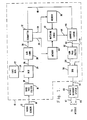
- Fig. 1 shows a block diagram representing of a digital system designed to suppress gunner jitter. It should be noted that while a digital system is disclosed, the principles of the present invention may be realized through equivalent analog circuitry.
- the gunner jitter suppression circuit is shown at 10 ir; Fig. 1.
- the suppression system 10 is adapted to receive video data from a video sensor 12.
- ThtA video sensor 12 may be a forward looking infrared (FLIR) sensor or an electronic T.V. camera.
- the video sensor block would also include a display and/or an optical sight through which the operator may view the video scene.
- the video output of sensor 12 appears on line 14 and is input to the bandpass filter 16.
- the bandpass filter 16 is effective as a differentiator to transform the video data so that subsequent correlations may be more easily measured and identified. The effect of differentiation is to delineate scene boundaries.
- the processing scheme of the present invention utilizes boundary change information to estimate gunner jitter.
- the output of the bandpass filter 16 provides one input to a multiplexer 20 via line 18.
- the second input to the multiplexer 20 is provided by the gate generator 22 via line 24.
- the multiplexer 20 and gate generator 22 operate on the analog video output of the filter in such a way as to pass data representing portions of the video scene remote from the center of the field of view.
- gated video appears at the output of multiplexer 20 on line 26 and is input to an analog-to-digital (A/D) converter 28.
- A/D analog-to-digital
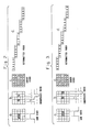
- the AID converter 28 thresholds the video data to produce a mosaic of 1's and 0's. See Figs. 2 and 3.
- This stream of binary video is input to a formatter 32 via line 30.
- the formatter 32 directs video data into a first memory 36 via line 34 until a first frame of gated video is stored. Similarly, video data is subsequently formatted into a second memory 40 via line 38.
- Video detector 12 bandpass filter 16, multiplexer 20, gate generator 22, analog-to-digital converter 28, and formatter 32 thus provide successive frames of video data for processing in the manner described below.
- the matching logic may be provided by a computer or other digital or analog circuitry.
- matching logic 42 samples frame 2 as it is being formatted into memory.
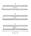
- the data in memory 40 is sampled and compared at every step or pixel. The location which gives the best overall match is referenced to the last frame's location in order to compute incremental motion. The process is illustrated in Fig. 4.
- Fig. 4a shows that at position N-1 there are 21 pixels which match and 4 pixels which do not match.
- the X's indicate "dont' cares”.
- Fig. 4b illustrates that the data has marched one position in time to where the number of matches is 25.
- Fig. 4b thus illustrates position N.
- Fig. 4c illustrates position N+1 where the number of matches is once again 21. Position N therefore provides the best match and indicates the displacement of the scene due to gunner jitter to be one pixel to the left.
- matching logic When matching logic detects the best match, it signals address latch 46 via line 44. At that point the address latch interrogates the formatter 32 to determine and store the position at which the best match is obtained. This information appears on line 48. The address latch 46 thus provides on line 50 information containing the jitter for say the ith sample or J,.
- Memories 36 and 40, matching logic 42, and address latch 46 thus provide means for analyzing successive frames of video data to provide signals indicative of jitter motion of the tracker relative to the video scene.
- Equation 1 illustrates that the jitter correction C for a given frame i is equal to the difference between the incremental jitter sample J; and the average of the previous n jitter samples
- Address latch 46 provides J, to low-pass filter 52 via line 50 and to subtractor 56 via line 51.
- Lowpass filter 52 provides the average of the previous jitter samples to the subtractor on line 54.
- the output of the subtractor on line 58 is the correction C for a frame i.
- Equation 1 can be verified functionally when one considers that in a situation where the gunner is in fact causing the tracker to undergo jitter, the effect of the jitter may be sinusoidal in nature. As a result, its average would be zero and the correction would equal the ith jitter sample. However, when the operator is tracking a target, the tracker position does not vary as a sinusoid but more as a ramp. The average behavior of a filtered ramp is another ramp delayed in time. Thus the corresponding correction would be the jitter which rides on the ramp. The filtered ramp is subtracted from this to leave a small value relative to the missile guidance signals.
- Fig. 1 the solution to the jitter/tracking ambiguity of Fig. 1 is illustrative of but one of several possible approaches to the problem.
- Another approach would be to utilize a high-pass filter to simply filter out the signals corresponding to the low frequency tracking motion of the tracker.
- Yet another approach would be to utilize an algorithm implemented by a microprocessor such as that which may be provided by the missile guidance system 60.
- the use of the low-pass filter and subtraction technique is preferred in so far as low-pass filters appear to function better as integrators than high-pass filters function as differentiators.
- the correction signal C is ultimately provided to the missile guidance system 60 via line 58 where it is subtracted from the missile guidance commands appearing on line 62 and 64.
- the low-pass filter 52, subtractor 56 and the missile guidance system provides means for compensating the missile guidance signals as a function of the jitter correction signals to provide signals for effectively guiding the missile notwithstanding jitter motion of the tracker.
Description
- This invention relates to a line-of-sight commanded missile guidance system according to the preamble of
Claim 1. - A typical line-of-sight commanded missile system as disclosed in US-A-3 885 453 and US-A-4 247 059 includes a launcher and a guided missile. The launcher typically includes a gunner's optical sight and an electronic guidance computer which automatically sends steering commands to the missile in flight. After launch, a beacon in the tail of the missile is activated and subsequently detected by a sensor on the launcher. The sensor is bore sighted with the gunners' telescope, and allows the operator to track the missile along its flight path. The sensor and associated processing circuitry measures the angle between the flight direction of the missile and the gunner's line-of-sight. These displacements are transformed by a computer into guidance commands which are sent to the missile over the command link. The gunner need only keep the cross-hairs of the sight on the target during missile flight.
- The US-A-4 220 967 discloses a scene tracker for use in an automatic target acquisition system. The known scene tracker comprises means for providing successive frames of data corresponding to at least a portion of a video scene as viewed by tracking means such as TV camera, infrared or radar imaging seekers or the like. These frames of data are stored and after a delay of one frame time compared with the actual frame of data, to find the "best match" between these two.
- Unfortunately, in an actual hostile operational environment, the operator may experience nervous jitters which would tend to impair his ability to maintain the cross-hairs of the optical sight in a line-of-sight commanded missile guidance system on the center of the target's most vulnerable aim point. Although the sight described in US-A-3 885 453 is provided with damping means, such jitter cannot be completely obviated. If the operator jitters the sensor line-of-sight, the missile tracker would measure a corresponding apparent missile off-set. As it corrected the nonexistent off-set, it would create perturbations which would appear as noise in the missile guidance signals. This would detract from the hit- accuracy of the guidance and tracking system.
- The object of the present invention is the elimination of the detrimental effects of jitter in line-of-sight commanded missile guidance systems.
- According to the invention this object is reached by:
- means for providing successive frames of data corresponding to at least a portion of a video scene as viewed by said tracking means;
- means for analyzing said frames of data and providing second signals indicative of jitter motion of said tracking means relative to said video scene; and
- means for compensating said first signals as a function of said second signals to provide signals for effectively guiding said missile notwithstanding any jitter motion of said tracking means.
- More specifically, the present invention includes means for converting information representative of the video scene into a train of discrete signals. Successive frames of discrete data are then compared on a pixel by pixel basis until a best match is obtained. (A "pixel" is an individual picture element). The address at which the best match is obtained provides information indicative of the jitter motion of the tracking system. (The "address" is the reference in number of rows and columns in each frame). Data must be successively displaced to achieve the best match to a prior frames reference (or address). This information is then utilized to off-set the jitter motion effect on the missile guidance signals.
-
- Fig. 1 is a diagrammatic representation of a preferred embodiment of the invention.
- Fig. 2 is representative of the processing of a first frame of video data by the system of the present invention.
- Fig. 3 is representative of the processing of a second frame of video data by the system of the present invention.
- Fig. 4 illustrates the method by which successive frames of data are compared by the system of the present invention.
- fhis invention substantially eliminates' the effect of gunner jitter by initially tracking arbitrary portions of the background of a video scene remote from the target. The basis for estimating the gunner jitter is the apparent motion of the stationary scene. By measuring how elements of the scene, remote from the target, appear to be moving, gunner jitter may be estimated. The estimation is represented by electrical signals which are subtracted from the missile guidance signals so that the normally occurring gunner jitter is suppressed.
- Fig. 1 shows a block diagram representing of a digital system designed to suppress gunner jitter. It should be noted that while a digital system is disclosed, the principles of the present invention may be realized through equivalent analog circuitry. The gunner jitter suppression circuit is shown at 10 ir; Fig. 1. The
suppression system 10 is adapted to receive video data from avideo sensor 12. ThtAvideo sensor 12 may be a forward looking infrared (FLIR) sensor or an electronic T.V. camera. The video sensor block would also include a display and/or an optical sight through which the operator may view the video scene. The video output ofsensor 12 appears online 14 and is input to thebandpass filter 16. Thebandpass filter 16 is effective as a differentiator to transform the video data so that subsequent correlations may be more easily measured and identified. The effect of differentiation is to delineate scene boundaries. The processing scheme of the present invention utilizes boundary change information to estimate gunner jitter. - The output of the
bandpass filter 16 provides one input to amultiplexer 20 vialine 18. The second input to themultiplexer 20 is provided by thegate generator 22 vialine 24. Themultiplexer 20 andgate generator 22 operate on the analog video output of the filter in such a way as to pass data representing portions of the video scene remote from the center of the field of view. Thus, gated video appears at the output ofmultiplexer 20 online 26 and is input to an analog-to-digital (A/D)converter 28. - The AID converter 28 thresholds the video data to produce a mosaic of 1's and 0's. See Figs. 2 and 3. This stream of binary video is input to a
formatter 32 vialine 30. Theformatter 32 directs video data into afirst memory 36 vialine 34 until a first frame of gated video is stored. Similarly, video data is subsequently formatted into asecond memory 40 vialine 38. - Figs. 2 and 3 illustrate the processing of the data up to this point. Fig. 2a shows that the first frame of data appears at the output of
video sensor 12 as raw video. The upper portion of the figure illustrates a portion of a typical video scene with the background clutter represented as a shaded area. The filtered video for the corresponding line of data is represented in the lower portion of the figure as a pulse two units wide. - Fig. 2b is illustrative of the same video band- passed by
filter 16. The upper portion of the figure now shows the boundaries as shaded areas while the lower portion of the figure is representative of the derivative of the pulse in Fig. 2a. - Fig. 2c shows the same portion of the video scene at the output of the analog-to-
digital converter 28. Shaded portions are represented by 1's; the remaining portions are represented by 0's. Fig. 2c is thus a mosaic of 1's and 0's.Formatter 32 provides the formatted video offrame 1 tomemory 36 in a format typified in Fig. 2d. - Fig. 3 illustrates that the second frame of data corresponds to a jitter motion effective to displace the sensor one element to the left. Note that the raw video of Fig. 2a is now moved to the right by one unit as illustrated in Fig. 3a. Subsequent filtering, digitalizing, and formatting, in the manner described above, yields a displacement of one unit to the right of the 1's in the data stream associated with line 3 of Fig. 3d.
-
Video detector 12,bandpass filter 16,multiplexer 20,gate generator 22, analog-to-digital converter 28, andformatter 32 thus provide successive frames of video data for processing in the manner described below. - Returning now to Fig. 1, the information stored in
memories logic 42. The matching logic may be provided by a computer or other digital or analog circuitry. - After
frame 1 is loaded inmemory 36, matchinglogic 42 samples frame 2 as it is being formatted into memory. The data inmemory 40 is sampled and compared at every step or pixel. The location which gives the best overall match is referenced to the last frame's location in order to compute incremental motion. The process is illustrated in Fig. 4. - Fig. 4a shows that at position N-1 there are 21 pixels which match and 4 pixels which do not match. The X's indicate "dont' cares". Fig. 4b illustrates that the data has marched one position in time to where the number of matches is 25. Fig. 4b thus illustrates position N. Fig. 4c illustrates position N+1 where the number of matches is once again 21. Position N therefore provides the best match and indicates the displacement of the scene due to gunner jitter to be one pixel to the left.
- When matching logic detects the best match, it signals
address latch 46 vialine 44. At that point the address latch interrogates theformatter 32 to determine and store the position at which the best match is obtained. This information appears online 48. Theaddress latch 46 thus provides online 50 information containing the jitter for say the ith sample or J,. -
Memories logic 42, and addresslatch 46 thus provide means for analyzing successive frames of video data to provide signals indicative of jitter motion of the tracker relative to the video scene. - What remains is to determine whether the incremental motion is in fact jitter motion or tracking motion. That is, scene stabilization must be selective. It must reduce effects of operator jitter while permitting accurate tracking of moving targets. Low-
pass filter 52 andsubtractor 56 serves to provide this function. The solution to this problem as afforded by the low-pass filter 52 and thesubtractor 56 is best illustrated byEquation 1.
- Where C is the ith correction corresponding to the ith frame the J, is the ith jitter sample.
Equation 1 illustrates that the jitter correction C for a given frame i is equal to the difference between the incremental jitter sample J; and the average of the previous n jitter samples -

-
Address latch 46 provides J, to low-pass filter 52 vialine 50 and to subtractor 56 vialine 51.Lowpass filter 52 provides the average of the previous jitter samples to the subtractor online 54. The output of the subtractor online 58 is the correction C for a frame i. -
Equation 1 can be verified functionally when one considers that in a situation where the gunner is in fact causing the tracker to undergo jitter, the effect of the jitter may be sinusoidal in nature. As a result, its average would be zero and the correction would equal the ith jitter sample. However, when the operator is tracking a target, the tracker position does not vary as a sinusoid but more as a ramp. The average behavior of a filtered ramp is another ramp delayed in time. Thus the corresponding correction would be the jitter which rides on the ramp. The filtered ramp is subtracted from this to leave a small value relative to the missile guidance signals. - It should be noted here that the solution to the jitter/tracking ambiguity of Fig. 1 is illustrative of but one of several possible approaches to the problem. Another approach would be to utilize a high-pass filter to simply filter out the signals corresponding to the low frequency tracking motion of the tracker. Yet another approach would be to utilize an algorithm implemented by a microprocessor such as that which may be provided by the
missile guidance system 60. The use of the low-pass filter and subtraction technique is preferred in so far as low-pass filters appear to function better as integrators than high-pass filters function as differentiators. - The correction signal C is ultimately provided to the
missile guidance system 60 vialine 58 where it is subtracted from the missile guidance commands appearing online - Thus, the low-
pass filter 52,subtractor 56 and the missile guidance system provides means for compensating the missile guidance signals as a function of the jitter correction signals to provide signals for effectively guiding the missile notwithstanding jitter motion of the tracker.
Claims (6)
Applications Claiming Priority (2)
| Application Number | Priority Date | Filing Date | Title |
|---|---|---|---|
| US260236 | 1981-05-04 | ||
| US06/260,236 US4474343A (en) | 1981-05-04 | 1981-05-04 | Jitter compensating scene stabilizing missile guidance system |
Publications (2)
| Publication Number | Publication Date |
|---|---|
| EP0064168A1 EP0064168A1 (en) | 1982-11-10 |
| EP0064168B1 true EP0064168B1 (en) | 1988-03-09 |
Family
ID=22988349
Family Applications (1)
| Application Number | Title | Priority Date | Filing Date |
|---|---|---|---|
| EP82102966A Expired EP0064168B1 (en) | 1981-05-04 | 1982-04-07 | Jitter compensated scene stabilized missile guidance system |
Country Status (6)
| Country | Link |
|---|---|
| US (1) | US4474343A (en) |
| EP (1) | EP0064168B1 (en) |
| JP (1) | JPS5875698A (en) |
| DE (1) | DE3278220D1 (en) |
| EG (1) | EG17923A (en) |
| IL (1) | IL65417A (en) |
Cited By (3)
| Publication number | Priority date | Publication date | Assignee | Title |
|---|---|---|---|---|
| US7962573B2 (en) | 2000-03-21 | 2011-06-14 | Intel Corporation | Method and apparatus to determine broadcast content and scheduling in a broadcast system |
| RU2460966C1 (en) * | 2011-03-14 | 2012-09-10 | Открытое акционерное общество "Конструкторское бюро приборостроения" | Method of beam control over rolling missile and beam-controlled rolling missile |
| US8943540B2 (en) | 2001-09-28 | 2015-01-27 | Intel Corporation | Method and apparatus to provide a personalized channel |
Families Citing this family (6)
| Publication number | Priority date | Publication date | Assignee | Title |
|---|---|---|---|---|
| US4672677A (en) * | 1984-11-19 | 1987-06-09 | Canon Kabushiki Kaisha | Character and figure processing apparatus |
| US4637571A (en) * | 1985-09-03 | 1987-01-20 | The United States Of America As Represented By The Secretary Of The Army | Electronic image stabilization |
| IL78757A0 (en) * | 1986-05-12 | 1986-08-31 | Israel State | Launcher for an optically guided,wire-controlled missile with improved electronic circuitry |
| US5990939A (en) * | 1995-09-28 | 1999-11-23 | Raytheon Company | Video demultiplexing interface for a missile tracking system |
| US7277558B2 (en) * | 2001-11-27 | 2007-10-02 | Lockheed Martin Corporation | Method and system for estimating the position of moving objects in images |
| US10429151B2 (en) | 2017-06-13 | 2019-10-01 | Raytheon Company | Recapture of remotely-tracked command guided vehicle into the tracker's field-of-view |
Family Cites Families (21)
| Publication number | Priority date | Publication date | Assignee | Title |
|---|---|---|---|---|
| US2930894A (en) * | 1954-07-13 | 1960-03-29 | Republic Aviat Corp | Optical sighting and tracking device |
| US3098933A (en) * | 1957-10-23 | 1963-07-23 | Republic Aviat Corp | Photosensitive electronic tracking head |
| NL285110A (en) * | 1961-11-06 | |||
| US3274552A (en) * | 1962-06-25 | 1966-09-20 | Martin Marietta Corp | Adaptive missile control system |
| US3998406A (en) * | 1964-05-28 | 1976-12-21 | Aeronutronic Ford Corporation | Guided missile system |
| US3820742A (en) * | 1965-02-08 | 1974-06-28 | R Watkins | Missile guidance and control system |
| US3954228A (en) * | 1965-11-16 | 1976-05-04 | The United States Of America As Represented By The Secretary Of The Army | Missile guidance system using an injection laser active missile seeker |
| GB1299851A (en) * | 1967-08-31 | 1972-12-13 | British Aircraft Corp Ltd | Improvements relating to missile tracking systems |
| US3711046A (en) * | 1969-10-22 | 1973-01-16 | H Barhydt | Automatic missile guidance system |
| US4027837A (en) * | 1969-10-23 | 1977-06-07 | The United States Of America As Represented By The Secretary Of The Army | Optical tracking link utilizing pulse burst modulation for solid state missile beacons |
| US4047678A (en) * | 1969-11-07 | 1977-09-13 | The United States Of America As Represented By The Secretary Of The Army | Modulated, dual frequency, optical tracking link for a command guidance missile system |
| US3829614A (en) * | 1970-02-11 | 1974-08-13 | Saab Scania Ab | Automatic video contrast tracker |
| US3885453A (en) * | 1970-06-19 | 1975-05-27 | Hughes Aircraft Co | Regulation of traversing movement of target alignment apparatus |
| US3751166A (en) * | 1971-06-03 | 1973-08-07 | Us Army | Command guidance transmitter system |
| DE2157672A1 (en) * | 1971-11-20 | 1973-05-24 | Messerschmitt Boelkow Blohm | ARRANGEMENT FOR THE STEERING OF AIRCRABTS BY USING A LASER |
| US3761180A (en) * | 1972-09-22 | 1973-09-25 | R Maxwell | Synchronously gated active night sight |
| US4047117A (en) * | 1974-01-17 | 1977-09-06 | Hughes Aircraft Company | Multi-level laser illuminator |
| FR2336655A1 (en) * | 1975-12-22 | 1977-07-22 | Telecommunications Sa | IMPROVEMENT IN NOCTURNAL GUIDANCE OF SELF-PROPELLED EQUIPMENT |
| GB1524122A (en) * | 1976-01-29 | 1978-09-06 | Elliott Brothers London Ltd | Guidance systems for mobile craft |
| US4220967A (en) * | 1976-09-27 | 1980-09-02 | Hughes Aircraft Company | Scene tracker using multiple independent correlators |
| US4247059A (en) * | 1978-10-25 | 1981-01-27 | The United States Of America As Represented By The Secretary Of The Army | Light emitting diode beacons for command guidance missile track links |
-
1981
- 1981-05-04 US US06/260,236 patent/US4474343A/en not_active Expired - Lifetime
-
1982
- 1982-04-02 IL IL65417A patent/IL65417A/en not_active IP Right Cessation
- 1982-04-07 DE DE8282102966T patent/DE3278220D1/en not_active Expired
- 1982-04-07 EP EP82102966A patent/EP0064168B1/en not_active Expired
- 1982-04-30 JP JP57073270A patent/JPS5875698A/en active Granted
- 1982-05-04 EG EG256/82A patent/EG17923A/en active
Cited By (5)
| Publication number | Priority date | Publication date | Assignee | Title |
|---|---|---|---|---|
| US7962573B2 (en) | 2000-03-21 | 2011-06-14 | Intel Corporation | Method and apparatus to determine broadcast content and scheduling in a broadcast system |
| US8108542B2 (en) | 2000-03-21 | 2012-01-31 | Intel Corporation | Method and apparatus to determine broadcast content and scheduling in a broadcast system |
| US8839298B2 (en) | 2000-03-21 | 2014-09-16 | Intel Corporation | Method and apparatus to determine broadcast content and scheduling in a broadcast system |
| US8943540B2 (en) | 2001-09-28 | 2015-01-27 | Intel Corporation | Method and apparatus to provide a personalized channel |
| RU2460966C1 (en) * | 2011-03-14 | 2012-09-10 | Открытое акционерное общество "Конструкторское бюро приборостроения" | Method of beam control over rolling missile and beam-controlled rolling missile |
Also Published As
| Publication number | Publication date |
|---|---|
| DE3278220D1 (en) | 1988-04-14 |
| JPS5875698A (en) | 1983-05-07 |
| JPH0152680B2 (en) | 1989-11-09 |
| IL65417A (en) | 1989-07-31 |
| EP0064168A1 (en) | 1982-11-10 |
| EG17923A (en) | 1991-03-30 |
| US4474343A (en) | 1984-10-02 |
Similar Documents
| Publication | Publication Date | Title |
|---|---|---|
| US3974328A (en) | Line scan area signature detection system | |
| US8792680B2 (en) | System and method for tracking moving objects | |
| US4739401A (en) | Target acquisition system and method | |
| US4424943A (en) | Tracking system | |
| EP0929787B1 (en) | Target aiming system | |
| US4270143A (en) | Cross-correlation video tracker and method | |
| US4316218A (en) | Video tracker | |
| US4849906A (en) | Dual mode video tracker | |
| US5323987A (en) | Missile seeker system and method | |
| EP0064168B1 (en) | Jitter compensated scene stabilized missile guidance system | |
| US4539590A (en) | Method and apparatus for processing optical tracking signals | |
| US6125308A (en) | Method of passive determination of projectile miss distance | |
| EP0226026A2 (en) | Aircraft automatic boresight correction | |
| US4407465A (en) | Method for guiding missiles | |
| US4103847A (en) | Line scan area signature detection method | |
| EP0911646A2 (en) | Imaging self-referencing tracker and associated methodology | |
| US5062586A (en) | Missile tracking, guidance and control apparatus | |
| US6496592B1 (en) | Method for tracking moving object by means of specific characteristics | |
| US5274236A (en) | Method and apparatus for registering two images from different sensors | |
| US6260792B1 (en) | Tracking and guidance system with modulated missile-mounted laser beacon | |
| EP0105432B1 (en) | Aircraft automatic boresight correction | |
| EP0381724B1 (en) | A segmentation method for use against moving objects | |
| US5848764A (en) | Body fixed terminal guidance system for a missile | |
| Rastogi et al. | Design of a real-time tracking system for fast-moving objects | |
| US5860619A (en) | Seeker head |
Legal Events
| Date | Code | Title | Description |
|---|---|---|---|
| PUAI | Public reference made under article 153(3) epc to a published international application that has entered the european phase |
Free format text: ORIGINAL CODE: 0009012 |
|
| AK | Designated contracting states |
Designated state(s): DE FR GB SE |
|
| 17P | Request for examination filed |
Effective date: 19830428 |
|
| RAP1 | Party data changed (applicant data changed or rights of an application transferred) |
Owner name: HUGHES AIRCRAFT COMPANY |
|
| GRAA | (expected) grant |
Free format text: ORIGINAL CODE: 0009210 |
|
| AK | Designated contracting states |
Kind code of ref document: B1 Designated state(s): DE FR GB SE |
|
| REF | Corresponds to: |
Ref document number: 3278220 Country of ref document: DE Date of ref document: 19880414 |
|
| ET | Fr: translation filed | ||
| PLBE | No opposition filed within time limit |
Free format text: ORIGINAL CODE: 0009261 |
|
| STAA | Information on the status of an ep patent application or granted ep patent |
Free format text: STATUS: NO OPPOSITION FILED WITHIN TIME LIMIT |
|
| 26N | No opposition filed | ||
| EAL | Se: european patent in force in sweden |
Ref document number: 82102966.7 |
|
| PGFP | Annual fee paid to national office [announced via postgrant information from national office to epo] |
Ref country code: FR Payment date: 19970307 Year of fee payment: 16 |
|
| PGFP | Annual fee paid to national office [announced via postgrant information from national office to epo] |
Ref country code: SE Payment date: 19970314 Year of fee payment: 16 |
|
| PGFP | Annual fee paid to national office [announced via postgrant information from national office to epo] |
Ref country code: DE Payment date: 19970321 Year of fee payment: 16 |
|
| PG25 | Lapsed in a contracting state [announced via postgrant information from national office to epo] |
Ref country code: SE Free format text: LAPSE BECAUSE OF NON-PAYMENT OF DUE FEES Effective date: 19980408 |
|
| PG25 | Lapsed in a contracting state [announced via postgrant information from national office to epo] |
Ref country code: FR Free format text: THE PATENT HAS BEEN ANNULLED BY A DECISION OF A NATIONAL AUTHORITY Effective date: 19980430 |
|
| EUG | Se: european patent has lapsed |
Ref document number: 82102966.7 |
|
| PG25 | Lapsed in a contracting state [announced via postgrant information from national office to epo] |
Ref country code: DE Free format text: LAPSE BECAUSE OF NON-PAYMENT OF DUE FEES Effective date: 19990202 |
|
| REG | Reference to a national code |
Ref country code: FR Ref legal event code: ST |
|
| REG | Reference to a national code |
Ref country code: GB Ref legal event code: 732E |
|
| PGFP | Annual fee paid to national office [announced via postgrant information from national office to epo] |
Ref country code: GB Payment date: 20000321 Year of fee payment: 19 |
|
| PG25 | Lapsed in a contracting state [announced via postgrant information from national office to epo] |
Ref country code: GB Free format text: LAPSE BECAUSE OF NON-PAYMENT OF DUE FEES Effective date: 20010407 |
|
| GBPC | Gb: european patent ceased through non-payment of renewal fee |
Effective date: 20010407 |