EP0062454B1 - Magnetic head apparatus for magnetic discs - Google Patents
Magnetic head apparatus for magnetic discs Download PDFInfo
- Publication number
- EP0062454B1 EP0062454B1 EP82301562A EP82301562A EP0062454B1 EP 0062454 B1 EP0062454 B1 EP 0062454B1 EP 82301562 A EP82301562 A EP 82301562A EP 82301562 A EP82301562 A EP 82301562A EP 0062454 B1 EP0062454 B1 EP 0062454B1
- Authority
- EP
- European Patent Office
- Prior art keywords
- slug
- arms
- channel
- sidewalls
- aligning
- Prior art date
- Legal status (The legal status is an assumption and is not a legal conclusion. Google has not performed a legal analysis and makes no representation as to the accuracy of the status listed.)
- Expired
Links
- 230000005291 magnetic effect Effects 0.000 title claims description 30
- 241000237858 Gastropoda Species 0.000 claims description 5
- 238000009987 spinning Methods 0.000 claims description 2
- 238000005299 abrasion Methods 0.000 description 1
- 230000001419 dependent effect Effects 0.000 description 1
- 238000011161 development Methods 0.000 description 1
- 230000018109 developmental process Effects 0.000 description 1
- 238000009429 electrical wiring Methods 0.000 description 1
- 230000006870 function Effects 0.000 description 1
- 238000003754 machining Methods 0.000 description 1
- 238000004519 manufacturing process Methods 0.000 description 1
- 238000003860 storage Methods 0.000 description 1
Images

Classifications
-
- G—PHYSICS
- G11—INFORMATION STORAGE
- G11B—INFORMATION STORAGE BASED ON RELATIVE MOVEMENT BETWEEN RECORD CARRIER AND TRANSDUCER
- G11B5/00—Recording by magnetisation or demagnetisation of a record carrier; Reproducing by magnetic means; Record carriers therefor
- G11B5/48—Disposition or mounting of heads or head supports relative to record carriers ; arrangements of heads, e.g. for scanning the record carrier to increase the relative speed
- G11B5/4806—Disposition or mounting of heads or head supports relative to record carriers ; arrangements of heads, e.g. for scanning the record carrier to increase the relative speed specially adapted for disk drive assemblies, e.g. assembly prior to operation, hard or flexible disk drives
- G11B5/4813—Mounting or aligning of arm assemblies, e.g. actuator arm supported by bearings, multiple arm assemblies, arm stacks or multiple heads on single arm
Definitions
- the present invention relates to magnetic head apparatus for use with a spinning pack of magnetic discs, comprising a carriage for positioning magnetic heads relative to the discs, a mounting channel in the carriage defined between first and second sidewalls, and a plurality of head arms mounted with ends thereof in the channel engaging means for aligning and supporting the arms, the arms being cantilevered out of the channel and carrying magnetic heads.
- Magnetic disc drive memory apparatus usually has one or more rigid rotatable discs coated with a material which permits storage of data on and retrieval of data from the disc surface.
- a recording head is positioned adjacent to the surface of each disc.
- the heads are moved parallel to the surface of the discs to position the read/write gaps of the heads adjacent to the appropriate location on the disc surface where a read or write transaction is to take place.
- a common type of rigid magnetic disc unit is the "IBM 3350" style disc drive.
- This unit has a plurality of magnetic rigid discs mounted about a central shaft. Each disc has one or more magnetic heads associated with it.
- the heads are mounted on head arms, up to four heads per arm.
- the head arms are mounted in a channel of the magnetic head carriage such that the head arms move in unison across the surface of the discs as the carriage moves.
- a typical head arm for use in this type of unit is the "Model 335004" manufactured by Applied Magnetics Corporation (USA).
- the present invention relates to an improved apparatus which is free from the above-mentioned disadvantages and problems.
- Magnetic discs 10 are mounted on a shaft 11.
- Magnetic head arms 20 are mounted in a channel 12 of a movable carriage 13 and are positioned in relation to the discs 10 by a motor 14 as required to accomplish read/write operations at various locations on a disc surface.
- Circuitry and wiring (not shown) for performing the read/write operations is attached to and extends from the magnetic head arms 20.
- Each head arm 20 has an associated clamping slug 32, aperture 43, bolt 30, aperture 44, aperture 45a and aperture 46a. These elements operate in conjunction with features of the mounting channel 12 (described below) to accomplish mounting of the head arms 20 on the carriage 13.
- a cross-section of the head arm mounting channel is substantially U-shaped, having a back wall and two substantially parallel side walls.
- Substantially identical ladder elements 45 and 46 are slidably mounted in channel grooves 47. Protruding sections 45c and 46c rest upon a carriage surface 48 when the ladder elements 45 and 46 are mounted in the channel and hold the ladder elements 45 and 46 in the proper vertical position.
- the ladder elements 45 and 46 have a like number of aligning apertures 45a and 46a therein.
- Each magnetic head arm 20 is mounted through an aperture 45a and 46a and is supported and aligned in the channel by a rung surfaces 45b and 46b.
- a clamping slug 32 is mounted through an aperture 43 such that the slug 32 protrudes into the channel.
- a bolt 30 is mounted through an aperture 44 in the opposite channel wall and mates with a threaded hole 34 in the slug 32. As the bolt 30 is turned, the slug 32 is drawn toward the magnetic head arm 20, causing surface 33 of the slug 32 to be pressed against an angled edge surface 23 of the magnetic head arm 20, thereby urging the magnetic head arm 20 into contact with the surfaces 45b and 46b of the ladder elements 45 and 46 and with an arcuate groove 41 in the opposite channel wall.
- the groove 41 is so located that only an edge 50 at the junction of surfaces 24 and 25 of the head arm 20 comes into contact with the channel wall as the slug 32 applies clamping force to the head arm.
- both the slug 32 and the groove 41 create vertical force components which hold the head arm in contact with the ladder elements 45 and 46.
- the head arm 20 is thereby firmly attached to the carriage 13 and undesired head arm movement is substantially precluded.
- Grooves 40 in one channel wall accommodate electrical wiring 22 of the magnetic head arm 20 so as to prevent abrasion of the wiring 22 during carriage movements and the aperture 44 is counter-bored so that the head of the bolt 30 does not protrude beyond the outer surface of the channel wall after the head arm is mounted.
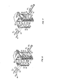
- FIG. 6 a perspective view of a segment of the head carriage similar to the view in Fig. 2 is presented.
- This is one alternative embodiment of the mounting means.
- the supporting and aligning function of the ladder elements 45 and 46 is now performed by pins 61 which are press fitted through apertures 62 in both channel walls such that pins 61 protrude into the channel and the magnetic head arm 20 rests thereon.
- FIG. 7 another perspective view of a segment of the head carriage similar to the view in Fig. 2 is presented.
- the countersunk aperture 44 has been replaced by an aperture 53, which is of substantially the same size as aperture 43.
- the bolt 30 passes through an aperture 51 in a slug 50 which fits in the aperture 53.
- the bolt 30 then mates with the aperture 34 in the slug 32.
- the slug 50 differs from the slug 32 only in that its aperture 51 is smooth while the aperture 34 is threaded.
- the need for grooves 41 in one channel wall has been eliminated because the head arm 20 is clamped between the two slugs, rather than being pressed against the wall.
- the slug 32 is drawn towards the slug 50, thereby forcing the head arm 20 into contact with the slugs 32 and 50 and the pins 61.
Landscapes
- Supporting Of Heads In Record-Carrier Devices (AREA)
Description
- The present invention relates to magnetic head apparatus for use with a spinning pack of magnetic discs, comprising a carriage for positioning magnetic heads relative to the discs, a mounting channel in the carriage defined between first and second sidewalls, and a plurality of head arms mounted with ends thereof in the channel engaging means for aligning and supporting the arms, the arms being cantilevered out of the channel and carrying magnetic heads.
- Magnetic disc drive memory apparatus usually has one or more rigid rotatable discs coated with a material which permits storage of data on and retrieval of data from the disc surface. To accomplish the read and write operations a recording head is positioned adjacent to the surface of each disc. During operation of the memory apparatus, the heads are moved parallel to the surface of the discs to position the read/write gaps of the heads adjacent to the appropriate location on the disc surface where a read or write transaction is to take place.
- A common type of rigid magnetic disc unit is the "IBM 3350" style disc drive. This unit has a plurality of magnetic rigid discs mounted about a central shaft. Each disc has one or more magnetic heads associated with it. The heads are mounted on head arms, up to four heads per arm. The head arms are mounted in a channel of the magnetic head carriage such that the head arms move in unison across the surface of the discs as the carriage moves. A typical head arm for use in this type of unit is the "Model 335004" manufactured by Applied Magnetics Corporation (USA).
- Apparatus of the kind referred to in the first paragraph above is disclosed in DE-A-2 846 599. The ends of the arms are received in opposed grooves in the two sidewalls.
- In this prior art the carriage channel is difficult and costly to manufacture as it requires a substantial amount of machining to be performed on the channel. The channel structure is weakened and unfavourable resonances can result, causing degraded head arm performance.
- The present invention relates to an improved apparatus which is free from the above-mentioned disadvantages and problems.
- The invention is defined in claim 1 below and advantageous developments of the invention are defined in the dependent claims.
- The invention will be described in more detail, by way of example, with reference to the accompanying drawings, in which:
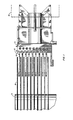
- Fig. 1 is a side view of several major elements of a magnetic disc unit;
- Fig. 2 is a perspective view of an illustrative embodiment of the present invention including a segment of the magnetic head carriage showing head arm mounting elements in an exploded position;
- Fig. 3 is a perspective view of a segment of the magnetic head carriage of Fig. 2 viewed from a different position to facilitate display of certain features;
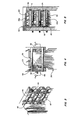
- Fig. 4 is a top view of the magnetic head carriage of Fig. 2 showing details of the apparatus after head arm mounting;
- Fig. 5 is a cross sectional view of the head carriage showing details of the apparatus after head arm mounting;
- Fig. 6 shows an alternative embodiment of the present invention; and
- Fig. 7 shows another alternative embodiment of the present invention.
- Referring to Fig. 1, a side view of a magnetic disc unit is presented.
Magnetic discs 10 are mounted on a shaft 11.Magnetic head arms 20 are mounted in achannel 12 of amovable carriage 13 and are positioned in relation to thediscs 10 by amotor 14 as required to accomplish read/write operations at various locations on a disc surface. Circuitry and wiring (not shown) for performing the read/write operations is attached to and extends from themagnetic head arms 20. - Referring now to Fig. 2, the mounting channel and head arm mounting elements are shown. Each
head arm 20 has an associatedclamping slug 32,aperture 43,bolt 30,aperture 44, aperture 45a andaperture 46a. These elements operate in conjunction with features of the mounting channel 12 (described below) to accomplish mounting of thehead arms 20 on thecarriage 13. - Referring to Figs. 2 to 5, a preferred embodiment of the invention is shown. It can be seen that a cross-section of the head arm mounting channel is substantially U-shaped, having a back wall and two substantially parallel side walls. Substantially
identical ladder elements channel grooves 47. Protrudingsections carriage surface 48 when theladder elements ladder elements ladder elements apertures 45a and 46a therein. Eachmagnetic head arm 20 is mounted through anaperture 45a and 46a and is supported and aligned in the channel by arung surfaces clamping slug 32 is mounted through anaperture 43 such that theslug 32 protrudes into the channel. Abolt 30 is mounted through anaperture 44 in the opposite channel wall and mates with a threadedhole 34 in theslug 32. As thebolt 30 is turned, theslug 32 is drawn toward themagnetic head arm 20, causingsurface 33 of theslug 32 to be pressed against anangled edge surface 23 of themagnetic head arm 20, thereby urging themagnetic head arm 20 into contact with thesurfaces ladder elements arcuate groove 41 in the opposite channel wall. Thegroove 41 is so located that only anedge 50 at the junction ofsurfaces head arm 20 comes into contact with the channel wall as theslug 32 applies clamping force to the head arm. At the point of contact between the head arm and the wall, the curvature of thegroove 41 is such that thehead arm 20 is urged downward against thesurfaces ladder elements slug 32 and thegroove 41 create vertical force components which hold the head arm in contact with theladder elements head arm 20 is thereby firmly attached to thecarriage 13 and undesired head arm movement is substantially precluded.Grooves 40 in one channel wall accommodateelectrical wiring 22 of themagnetic head arm 20 so as to prevent abrasion of thewiring 22 during carriage movements and theaperture 44 is counter-bored so that the head of thebolt 30 does not protrude beyond the outer surface of the channel wall after the head arm is mounted. - Referring to Fig. 6, a perspective view of a segment of the head carriage similar to the view in Fig. 2 is presented. This is one alternative embodiment of the mounting means. The supporting and aligning function of the
ladder elements pins 61 which are press fitted throughapertures 62 in both channel walls such thatpins 61 protrude into the channel and themagnetic head arm 20 rests thereon. - Referring to Fig. 7, another perspective view of a segment of the head carriage similar to the view in Fig. 2 is presented. There is another alternative embodiment of the mounting means. The
countersunk aperture 44 has been replaced by anaperture 53, which is of substantially the same size asaperture 43. In this figure, thebolt 30 passes through anaperture 51 in aslug 50 which fits in theaperture 53. Thebolt 30 then mates with theaperture 34 in theslug 32. Theslug 50 differs from theslug 32 only in that itsaperture 51 is smooth while theaperture 34 is threaded. The need forgrooves 41 in one channel wall has been eliminated because thehead arm 20 is clamped between the two slugs, rather than being pressed against the wall. As thebolt 30 is turned, theslug 32 is drawn towards theslug 50, thereby forcing thehead arm 20 into contact with theslugs pins 61.
Claims (9)
Applications Claiming Priority (2)
| Application Number | Priority Date | Filing Date | Title |
|---|---|---|---|
| US248764 | 1981-03-30 | ||
| US06/248,764 US4387409A (en) | 1981-03-30 | 1981-03-30 | Magnetic head arm mounting apparatus |
Publications (3)
| Publication Number | Publication Date |
|---|---|
| EP0062454A2 EP0062454A2 (en) | 1982-10-13 |
| EP0062454A3 EP0062454A3 (en) | 1983-04-06 |
| EP0062454B1 true EP0062454B1 (en) | 1985-11-21 |
Family
ID=22940578
Family Applications (1)
| Application Number | Title | Priority Date | Filing Date |
|---|---|---|---|
| EP82301562A Expired EP0062454B1 (en) | 1981-03-30 | 1982-03-24 | Magnetic head apparatus for magnetic discs |
Country Status (4)
| Country | Link |
|---|---|
| US (1) | US4387409A (en) |
| EP (1) | EP0062454B1 (en) |
| JP (1) | JPS57176569A (en) |
| DE (1) | DE3267512D1 (en) |
Families Citing this family (7)
| Publication number | Priority date | Publication date | Assignee | Title |
|---|---|---|---|---|
| US4443824A (en) * | 1981-09-14 | 1984-04-17 | International Business Machines Corporation | Magnetic head arm assembly |
| JPS63249457A (en) * | 1987-04-03 | 1988-10-17 | Toshiba Corp | Linear actuator |
| US4947275A (en) * | 1988-03-23 | 1990-08-07 | Digital Equipment Corp. | Detachable head-load beam slider arm for disk drive |
| US4912583A (en) * | 1988-03-23 | 1990-03-27 | Digital Equipment Corporation | Clamp for mounting head-load beam slider arm in a disk drive |
| US5040086A (en) * | 1988-12-07 | 1991-08-13 | Mitsubishi Denki Kabushiki Kaisha | Positioning mechanism for a head of a magnetic disk drive |
| JPH0677288B2 (en) * | 1989-02-16 | 1994-09-28 | インターナショナル・ビジネス・マシーンズ・コーポレーション | Disk file head / arm assembly carrier and mounting method |
| US5249092A (en) * | 1989-10-27 | 1993-09-28 | International Business Machines Corporation | Head lead termination |
Family Cites Families (6)
| Publication number | Priority date | Publication date | Assignee | Title |
|---|---|---|---|---|
| US3743794A (en) * | 1972-03-02 | 1973-07-03 | Hewlett Packard Co | Translational motion apparatus for the magnetic transducers of a disc memory |
| US3786457A (en) * | 1972-10-24 | 1974-01-15 | Memorex Corp | Disk recorder arm assembly mount |
| US4107748A (en) * | 1977-05-31 | 1978-08-15 | Memorex Corporation | Recording head support assembly |
| SU732988A1 (en) * | 1978-03-28 | 1980-05-05 | Предприятие П/Я А-3103 | Device for securing magnetic heads |
| DE2846599A1 (en) * | 1978-10-26 | 1980-04-30 | Basf Ag | DEVICE FOR POSITIONING LOW-SIZE ITEMS |
| JPS5570971A (en) * | 1978-11-20 | 1980-05-28 | Toshiba Corp | Magnetic head positioning mechanism |
-
1981
- 1981-03-30 US US06/248,764 patent/US4387409A/en not_active Expired - Lifetime
-
1982
- 1982-03-24 DE DE8282301562T patent/DE3267512D1/en not_active Expired
- 1982-03-24 EP EP82301562A patent/EP0062454B1/en not_active Expired
- 1982-03-30 JP JP57052209A patent/JPS57176569A/en active Pending
Also Published As
| Publication number | Publication date |
|---|---|
| JPS57176569A (en) | 1982-10-29 |
| US4387409A (en) | 1983-06-07 |
| EP0062454A2 (en) | 1982-10-13 |
| EP0062454A3 (en) | 1983-04-06 |
| DE3267512D1 (en) | 1986-01-02 |
Similar Documents
| Publication | Publication Date | Title |
|---|---|---|
| US5313355A (en) | Flexure mounting system for hard disc drives | |
| US3766327A (en) | Tape cassette holding and positioning unit | |
| EP0062454A2 (en) | Magnetic head apparatus for magnetic discs | |
| EP0230610B1 (en) | Cassette tape recording and/or reproducing apparatus | |
| US5657531A (en) | Magnetic head arm, method of producing the same and apparatus for producing the same | |
| US3786457A (en) | Disk recorder arm assembly mount | |
| EP0056798B1 (en) | Information recording apparatus with a disc loaded in a cassette | |
| JPH0755757Y2 (en) | Recording / playback device replacement adapter | |
| JP3658446B2 (en) | cartridge | |
| US6353514B1 (en) | Two-sided compliant tape guide | |
| EP0549020B1 (en) | Apparatus suitable for cooperation with a cassette provided with magnetic tape, magnetic-head unit and magnetic-head for use in the apparatus, housing suitable for use in the magnetic-head unit, and method of manufacturing the magnetic-head unit | |
| US5562258A (en) | Belt driven cartridge for guiding tape with reduced offtracking | |
| DE60033111T2 (en) | Device for disc cartridges | |
| US4860967A (en) | Magnetic-tape cassette and tape-pressure member for use in such a cassette | |
| US4609955A (en) | Latching mechanism for a tape carrier | |
| US5396390A (en) | Magnetic head assembly for floppy disc drive | |
| US4881145A (en) | Tape guide mechanism | |
| US4809427A (en) | Method for assembling a magnetic head supporting mechanism of a flexible disk drive apparatus | |
| EP0920010B1 (en) | Magnetic disk cartridge | |
| US5724207A (en) | Cassette holder for individually holding different size cassettes | |
| KR100466752B1 (en) | Magnetic-tape-cassette apparatus | |
| US4621295A (en) | Floppy disk drive having improved frame means | |
| US4989197A (en) | Apparatus for playing cartridge-stored disc | |
| KR200171472Y1 (en) | Cassette guide apparatus of tape recorder | |
| US7136259B2 (en) | Frame structure and flexible disk drive having the same |
Legal Events
| Date | Code | Title | Description |
|---|---|---|---|
| PUAI | Public reference made under article 153(3) epc to a published international application that has entered the european phase |
Free format text: ORIGINAL CODE: 0009012 |
|
| AK | Designated contracting states |
Designated state(s): DE FR GB |
|
| PUAL | Search report despatched |
Free format text: ORIGINAL CODE: 0009013 |
|
| AK | Designated contracting states |
Designated state(s): DE FR GB |
|
| 17P | Request for examination filed |
Effective date: 19830927 |
|
| GRAA | (expected) grant |
Free format text: ORIGINAL CODE: 0009210 |
|
| AK | Designated contracting states |
Designated state(s): DE FR GB |
|
| REF | Corresponds to: |
Ref document number: 3267512 Country of ref document: DE Date of ref document: 19860102 |
|
| ET | Fr: translation filed | ||
| PLBE | No opposition filed within time limit |
Free format text: ORIGINAL CODE: 0009261 |
|
| STAA | Information on the status of an ep patent application or granted ep patent |
Free format text: STATUS: NO OPPOSITION FILED WITHIN TIME LIMIT |
|
| 26N | No opposition filed | ||
| PGFP | Annual fee paid to national office [announced via postgrant information from national office to epo] |
Ref country code: FR Payment date: 19890208 Year of fee payment: 8 |
|
| PGFP | Annual fee paid to national office [announced via postgrant information from national office to epo] |
Ref country code: DE Payment date: 19890214 Year of fee payment: 8 |
|
| PGFP | Annual fee paid to national office [announced via postgrant information from national office to epo] |
Ref country code: GB Payment date: 19890228 Year of fee payment: 8 |
|
| PG25 | Lapsed in a contracting state [announced via postgrant information from national office to epo] |
Ref country code: GB Effective date: 19900324 |
|
| GBPC | Gb: european patent ceased through non-payment of renewal fee | ||
| PG25 | Lapsed in a contracting state [announced via postgrant information from national office to epo] |
Ref country code: FR Effective date: 19901130 |
|
| PG25 | Lapsed in a contracting state [announced via postgrant information from national office to epo] |
Ref country code: DE Effective date: 19901201 |
|
| REG | Reference to a national code |
Ref country code: FR Ref legal event code: ST |