EP0062412B1 - Wire-laying tool - Google Patents
Wire-laying tool Download PDFInfo
- Publication number
- EP0062412B1 EP0062412B1 EP82301172A EP82301172A EP0062412B1 EP 0062412 B1 EP0062412 B1 EP 0062412B1 EP 82301172 A EP82301172 A EP 82301172A EP 82301172 A EP82301172 A EP 82301172A EP 0062412 B1 EP0062412 B1 EP 0062412B1
- Authority
- EP
- European Patent Office
- Prior art keywords
- wire
- probe
- passageway
- actuator
- laying tool
- Prior art date
- Legal status (The legal status is an assumption and is not a legal conclusion. Google has not performed a legal analysis and makes no representation as to the accuracy of the status listed.)
- Expired
Links
Images
Classifications
-
- H—ELECTRICITY
- H05—ELECTRIC TECHNIQUES NOT OTHERWISE PROVIDED FOR
- H05K—PRINTED CIRCUITS; CASINGS OR CONSTRUCTIONAL DETAILS OF ELECTRIC APPARATUS; MANUFACTURE OF ASSEMBLAGES OF ELECTRICAL COMPONENTS
- H05K13/00—Apparatus or processes specially adapted for manufacturing or adjusting assemblages of electric components
- H05K13/06—Wiring by machine
-
- H—ELECTRICITY
- H01—ELECTRIC ELEMENTS
- H01B—CABLES; CONDUCTORS; INSULATORS; SELECTION OF MATERIALS FOR THEIR CONDUCTIVE, INSULATING OR DIELECTRIC PROPERTIES
- H01B13/00—Apparatus or processes specially adapted for manufacturing conductors or cables
- H01B13/012—Apparatus or processes specially adapted for manufacturing conductors or cables for manufacturing wire harnesses
- H01B13/01236—Apparatus or processes specially adapted for manufacturing conductors or cables for manufacturing wire harnesses the wires being disposed by machine
- H01B13/01245—Apparatus or processes specially adapted for manufacturing conductors or cables for manufacturing wire harnesses the wires being disposed by machine using a layout board
-
- Y—GENERAL TAGGING OF NEW TECHNOLOGICAL DEVELOPMENTS; GENERAL TAGGING OF CROSS-SECTIONAL TECHNOLOGIES SPANNING OVER SEVERAL SECTIONS OF THE IPC; TECHNICAL SUBJECTS COVERED BY FORMER USPC CROSS-REFERENCE ART COLLECTIONS [XRACs] AND DIGESTS
- Y10—TECHNICAL SUBJECTS COVERED BY FORMER USPC
- Y10T—TECHNICAL SUBJECTS COVERED BY FORMER US CLASSIFICATION
- Y10T29/00—Metal working
- Y10T29/49—Method of mechanical manufacture
- Y10T29/49002—Electrical device making
- Y10T29/49117—Conductor or circuit manufacturing
- Y10T29/49124—On flat or curved insulated base, e.g., printed circuit, etc.
- Y10T29/49155—Manufacturing circuit on or in base
- Y10T29/49162—Manufacturing circuit on or in base by using wire as conductive path
Definitions
- This invention relates to the laying of wire and in particular to a tool capable of use in the laying of wire in the production of a wiring harness with the aid of a wiring loom table.
- the present invention concerns a wire-laying tool which is capable of use in conjunction with a wire-laying robot, such as is mentioned in our European Patent Specification EP-A-0008155 for the purpose of laying wire in the production of a wiring harness in the manner described in, for example, our British Patent Specification GB-A-2025272 and European Patent Specification EP-A-0062413.
- Those methods form no part of the present invention.
- they have the common characteristic of a loom table which consists of, among other things, a wire mesh into which a programmed robot places, using a suitable gripping tool, a multiplicity of pins in a pattern appropriate for the particular harness which is to be made.
- the harness usually consists of a multiplicity of wires which start and terminate in respective positions but over a considerable portion of their lengths are laid along a common path.
- European Patent Specification EP-A-0062413 we describe a method of production in which when the pins have been laid out in the desired pattern, some of them are provided with rubber collars so that when the wires are laid adjacent to pins having rubber collars the wires are supported clear of the topmost mesh of the wiring table.
- the robot exchanges the tool which is used for laying pins for another adapted for picking up the rubber collars and depositing those rubber collars over the relevant pins. Thereafter the robot exchanges that tool for another tool which is adapted for the laying of wire.
- This tool which is preferably constituted by a tool according to the present invention, is, for each wire in the harness, fed with a metered length of wire and is then moved by the robot so that for each wire the leading end is wound round a "start" pin, then the balance of the wire is laid along the programmed path appropriate for that wire and finally the wire is wound around a final pin. This operation is repeated for each wire. Subsequently, the wiring harness is removed from the table, preferably by inversion of the table, which is then ready, on reinversion to be rewired with another, similar harness. At the end of a run of production of a multiplicity of harnesses, the table is finally inverted and, as described in our British Patent Specification GB-A-2025272, two meshes in the table are separated to remove the pins from the table.
- a wire-laying tool according to the invention is characterised by a probe which is movably mounted with respect to the stem constituting a forward extension of the passageway and a resettable actuator arranged to retract the probe with respect of the stem.
- the actuator for advancing the wire relative to the probe is coupled to a pawl arranged to bear on wire in the passageway; the second actuator is responsive to the completion of a predetermined movement of the first actuator to retract the probe relative to said stem portion.
- the first actuator comprises a fluid piston and cylinder of which the piston is coupled to the pawl and of which the cylinder has an inlet for supply of fluid pressure to the piston and a port arranged to be in communication with the inlet when the piston has executed a predetermined movement and the second actuator comprises a piston and cylinder of which the piston is coupled to the said terminal portion, said port being connected to supply fluid pressure to the second cylinder.
- the stem may comprise a sleeve in which the said probe is slidably movable and relative to which the probe extends forwardly.
- the tool shown in the drawings has a body 1 which has a longitudinal passageway 2. At the rear end 3 of the tool the passageway is flared and has a deflector plate 3a so that the tool can receive from a feeder wire which would usually be fed into the tool to the front end thereof. By means not relevant to the present invention feeding of the wire would continue, the wire falling in a loop extending from the rear end of the tool, the remote end of the wire being severed when a metered length has been delivered.
- This body 4 which contains two actuators which will be described hereinafter with reference to Figure 2.
- This body 4 carries an oblique lateral bayonet fitting 5 by means of which the tool can be attached to a standard robot head which includes a pneumatic line.
- the fitting 5 serves not only as a mount for the tool but as a means for receiving pneumatic pressure from a source (not shown).
- the body 1 Forwardly of the body 4 the body 1 terminates in a hollow stem 6 which constitutes a sleeve for an elongate hollow probe 7 which has an internal passageway 8 and terminates in a chamfered end 9.
- the probe 7 extends internally of the sleeve and the passageway 2 back to a location rearward of the body 4.
- the rearward end 10 of the probe 7 is attached by means of a connecting lug 11 and a locking nut 12 to a threaded stem 13 which extends from the head 14 of a piston 15 disposed within a cylinder 16 defined within the body 4.
- a compression spring 17 is mounted on the stem 13, one end of the spring being disposed within a recess 18 at the rear of the head 14 and the other end of the spring bearing on an end face 19 of the cylinder 16.
- the cylinder is laterally defined by the body 4 and is closed at each end by end plates 20, 21 respectively for the body 4.
- the stem 13 extends out of the rear end plate 21 through an aperture 22 and the forward end of the cylinder 16 is sealed by means of a circular sealing ring 23 disposed within a recess 24 formed in the plate 20 and aligned with the cylinder 16.
- a port 25 interconnects the front end of the cylinder 16 to another cylinder 26 extending, as does the cylinder 16, longitudinally of the body 4 and defined between the body 4 and the two end plates 20 and 21.
- An inlet 26a for this cylinder is at the rearward end of the body 4.
- the cylinder terminates in a recess 28 formed in the end plate 21, the recess containing a circular seal 27 by means of which the plate 21 and the body 4 are sealed at this end of the cylinder.
- the port 25 provides communication between the cylinder 16 and that region of the cylinder 26 remote from the inlet end thereof.
- a piston 29 is disposed in the cylinder 26.
- the piston 29 has a head 30 from which extends a stem 31 through an aperture 32 in the plate 20.
- the stem is threaded and by means of a locking nut 33 a lug 34 is secured to the stem 31.
- a compression spring 35 is disposed on the stem and extends between a recess 37 in the rear of the head 30 to the end face 36 presented by the plate 20 to the chamber 26.
- the lug 34 carries a pawl 38 which is biassed by a spring 39.
- This pawl will bear on wire 42 within the stem 6.
- the pawl can move longitudinally of the stem 6 and for this purpose is accommodated in a slot 41 extending longitudinally in the wall of the stem 6.
- This slot accommodates a spring-loaded dog 45 which constitutes a means for preventing rearward movement of the wire within the passageway 2.
- the dog 45 allows forward movement of the wire but the rearward movement of the wire causes the dog to engage the wire with sufficient force to prevent more than a very slight rearward movement.
- the tool would normally be loaded with wire while it is held horizontally, the wire being fed in up to the tip 9. This operation will be described in more detail later.
- the head would be moved to the place at which laying is to start and would be rotated to an upright position.
- FIG. 5 illustrates one mode of use of the tool in conjunction with a worktable which forms the subject of our European Patent Specification EP-A-0062413 of even date herewith.
- This table comprises a base board 50 on which is disposed a layer of penetrable supporting material 51 overlaid by a rubber sheet 52.
- the board and the two sheets above it are supported by a side frame 53 which has clamps 54, of which only one is schematically illustrated, for the retention of the board 50 in the frame.
- Extending around the frame 53 is a further frame 55 made of elongate angle members of which the horizontal part extends over the respective adjacent part of the frame 53 and of which the vertical parts are disposed laterally of the frame 53.
- the frame 55 Between the horizontal parts 56 of the frame 55 and the frame 53 is the side margin of a lower steel mesh 57 disposed thereby immediately above the rubber sheet 52.
- Above the frame 55 are two similar frames 58 and 59, disposed immediately one above the other, the upper frame 59 being disposed partly to enclose the frame 58 and the frame 58 partly enclosing the frame 55.
- the frame 58 carries an upper steel mesh 60 which is separated from and above the mesh 57.
- the frame 59 carries a nylon mesh 61 disposed immediately above the upper steel mesh 60.
- a pin 62 which is preferably double-ended, having a central portion 63 of slightly larger diameter than the remainder of the pin and two shanks 64 and 65 extending one from each end of the central portion 63.
- Each shank terminates in a head separated from the shank by a narrow neck, only the head 66 and the neck 67 at the lower end of the pin being illustrated.
- Such a form of pin is preferable so that a robot head which inserts the pins in the table does not have to distinguish one end of the pin from the other.
- the pin 62 is one of an array of pins which are laid to define the harness which is to be produced.
- the particular pin which is shown is selected to be a start pin for the laying of a particular wire.
- Figure 5 shows, schematically, the tool 68 disposed adjacent and parallel to the pin 62.
- the wire 69 with which the tool has been fed trails out of the rear, now the top end of the tool 68.
- the tool is shown schematically as carried by an arm 70 of a robot, which may be a Unimation robot made under the trade name "PUMA".
- the frame 59 can be moved so as to separate the meshes 61 and 60 and that the frame 58 can be moved together with the frame 59 so as to increase the separation of the meshes 57 and 60.
- the pins such as pin 62 are inserted in the table, they are inserted so that they penetrate the two meshes 60 and 57 and so that their heads (66) enter the sheet 51, having passed through the sheet 52.
- the purpose of this arrangement is to enable the harness when it is completed to be removed from the table by the separation of the nylon mesh 61 from the mesh 60, this separation being preferably accompanied by an inversion of the worktable so that the harness can fall on to a conveyor.
- the meshes 60 and 57 may be separated, by movement of the frames 58 and 59 relative to the frame 55 so that, because the portion 63 of the pin cannot pass through the steel mesh 60, the heads of the pins are pulled out of the material 51, the sheet 52 and the lower mesh 57.
- This separation of the frames preferably occurs after an inversion of the table so that the pins can fall on to a conveyor and be conveyed thence to a feeder ready for another production cycle.
- the preferred manner of commencing the wire-laying operation is to actuate the tool 68 so that the wire held within it is advanced a short distance from the tip of the probe and is thereby injected through the meshes 61, 60 and 57 so as to provide a temporary anchorage for the leading end of the wire.
- the end of the probe should be close to the mesh 60.
- the tool may be caused to execute a circular movement around the adjacent pin so as to loop the wire around the pin.
- the tool is traversed across the table, the wire being gradually drawn through the tool and laid along the predetermined path, having been anchored to the start pin 62.
- the remote end of the wire may be wound around a final pin by the execution of a circular movement around the pin by the tool 68.
- the height of the forward end of the probe during the laying of the wire should normally be somewhat higher than it is for the injection of the wire into the top mesh. As will be made apparent, the forward movement of the wire for injection is automatically followed by retraction of the probe 7 relative to the stem 6 so that the height of the lower end of the probe is suitable for the looping of the wire around the start pin 62 and the subsequent laying of the wire. This height is preferably, just above the upper shoulder on pin 62.
- the internal actions of the tool for the reception of wire from its feed and for the injection of wire into the top mesh are as follows.
- the probe is in its extended position under the influence of the spring 17 and wire is fed in until the leading end reaches the tip 9 of the probe, passing the pawl 38.
- the wire is held by the action of this pawl and the dog 45.
- the tool is moved to the required position and is turned by the robot from a horizontal to a vertical position, such that the tip 9 is just above the mesh 61.
- Pneumatic pressure is then applied to the inlet 5 to produce movement of the piston 29 in the cylinder 26: the pawl is moved along the slot 41, pushing the wire forwardly of the tool by a distance sufficient to advance the leading end of the wire through the meshes 61, 60 and 57.
- the port 25 When the piston 29 reaches the end of its travel, the port 25 is exposed to the fluid pressure applied to the chamber 26 and communicates that fluid pressure to the chamber 16 so as to cause the piston 15 to move leftwardly as shown in the drawing and thereby to cause the retraction of the probe 7 relative to the stem 6.
- the stroke of the actuator constituted by the piston 15 and cylinder 16 is sufficient to draw the tip 9 wholly into the sleeve constituted by the stem 6. Relaxation of the pressure then permits the probe to return to its forward position and the pawl to return to its original position.
- the probe 7 is retracted relative to the stem and is maintained thus by the continual application of pressure to the fitting 5 for the duration of the respective wire-laying run.
- the pressure applied to the inlet of the cylinder 26 may be relieved, whereupon the two pistons return under the restoring forces of the return springs 17 and 35 to their original positions.
Landscapes
- Engineering & Computer Science (AREA)
- Manufacturing & Machinery (AREA)
- Microelectronics & Electronic Packaging (AREA)
- Manipulator (AREA)
- Electric Cable Installation (AREA)
- Basic Packing Technique (AREA)
Description
- This invention relates to the laying of wire and in particular to a tool capable of use in the laying of wire in the production of a wiring harness with the aid of a wiring loom table.
- More particularly the present invention concerns a wire-laying tool which is capable of use in conjunction with a wire-laying robot, such as is mentioned in our European Patent Specification EP-A-0008155 for the purpose of laying wire in the production of a wiring harness in the manner described in, for example, our British Patent Specification GB-A-2025272 and European Patent Specification EP-A-0062413. Those methods form no part of the present invention. However, they have the common characteristic of a loom table which consists of, among other things, a wire mesh into which a programmed robot places, using a suitable gripping tool, a multiplicity of pins in a pattern appropriate for the particular harness which is to be made. The harness usually consists of a multiplicity of wires which start and terminate in respective positions but over a considerable portion of their lengths are laid along a common path. In European Patent Specification EP-A-0062413 we describe a method of production in which when the pins have been laid out in the desired pattern, some of them are provided with rubber collars so that when the wires are laid adjacent to pins having rubber collars the wires are supported clear of the topmost mesh of the wiring table. For this purpose the robot exchanges the tool which is used for laying pins for another adapted for picking up the rubber collars and depositing those rubber collars over the relevant pins. Thereafter the robot exchanges that tool for another tool which is adapted for the laying of wire. This tool, which is preferably constituted by a tool according to the present invention, is, for each wire in the harness, fed with a metered length of wire and is then moved by the robot so that for each wire the leading end is wound round a "start" pin, then the balance of the wire is laid along the programmed path appropriate for that wire and finally the wire is wound around a final pin. This operation is repeated for each wire. Subsequently, the wiring harness is removed from the table, preferably by inversion of the table, which is then ready, on reinversion to be rewired with another, similar harness. At the end of a run of production of a multiplicity of harnesses, the table is finally inverted and, as described in our British Patent Specification GB-A-2025272, two meshes in the table are separated to remove the pins from the table.
- It is, for the practice of the method which has been described in the foregoing paragraph and in similar methods desirable to provide a tool by means of which a wire can be wound around an upstanding pin and laid along a path. These two functions can be fulfilled by means of a hollow probe which can be held upright and traversed quickly in a smaller circle about the pin so as to loop the leading end of the wire around that pin, the probe thereafter merely serving as a guide for the wire, which is drawn through the probe by the movement of the probe along the predetermined path and the anchoring of the leading end of the wire by its loop around the start pin. A tool according to the present invention is intended to be capable of these functions but is adapted to facilitate such an operation by means hereinafter described. It is desirable to provide a secure, albeit temporary, anchorage for the wire before it is wound around the start pin. In order to achieve this, it may be necessary to inject a short part of the leading end of the wire into an intermediate mesh. For this purpose the leading end of the probe must be held close to the mesh. However, during the remainder of the wiring operation, the lowermost extremity of the probe must be rather higher than is appropriate for the injection of the wire into the mesh. Moreover, it is desirable to provide an efficient means in the tool for holding the leading end of the wire as it is fed into the tool so that a properly metered length can be supplied to the tool. It is an object of the present invention to provide a tool which can provide these functions and it is a further object of the invention to provide a tool which performs those functions in a simple and reliable manner.
- It is known from US-A-3019822 to provide a wire laying tool comprising an elongate body having a longitudinal passageway adapted for the passage of wire from a rear end to a front end, and a resettable actuator arranged to advance wire unidirectionally relative to the passageway. US-A-3960309 discloses a similar structure which is, however, intended for the feeding of pre-twisted wires.
- A wire-laying tool according to the invention is characterised by a probe which is movably mounted with respect to the stem constituting a forward extension of the passageway and a resettable actuator arranged to retract the probe with respect of the stem.
- In an embodiment of the invention the actuator for advancing the wire relative to the probe is coupled to a pawl arranged to bear on wire in the passageway; the second actuator is responsive to the completion of a predetermined movement of the first actuator to retract the probe relative to said stem portion.
- In a particular embodiment of the invention the first actuator comprises a fluid piston and cylinder of which the piston is coupled to the pawl and of which the cylinder has an inlet for supply of fluid pressure to the piston and a port arranged to be in communication with the inlet when the piston has executed a predetermined movement and the second actuator comprises a piston and cylinder of which the piston is coupled to the said terminal portion, said port being connected to supply fluid pressure to the second cylinder.
- The stem may comprise a sleeve in which the said probe is slidably movable and relative to which the probe extends forwardly.
- For inhibiting movement of the wire back through the passageway, there may be a spring-loaded dog which protrudes into the passageway.
- There follows a description of a particular embodiment of this invention by way of example and with reference to the accompanying drawings, in which:-
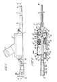
- Figure 1 is a side elevation of a wire-laying tool;
- Figure 2 is a section on the line A-A of Figure 1;
- Figure 3 is a front elevation of the wire-laying tool;
- Figure 4 is a section on the line B-B of Figure 3; and
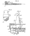
- Figure 5 illustrates one manner of operation of the tool.
- The tool shown in the drawings has a
body 1 which has alongitudinal passageway 2. At the rear end 3 of the tool the passageway is flared and has a deflector plate 3a so that the tool can receive from a feeder wire which would usually be fed into the tool to the front end thereof. By means not relevant to the present invention feeding of the wire would continue, the wire falling in a loop extending from the rear end of the tool, the remote end of the wire being severed when a metered length has been delivered. - Mounted on the
body 1 is anotherbody 4 which contains two actuators which will be described hereinafter with reference to Figure 2. Thisbody 4 carries an oblique lateral bayonet fitting 5 by means of which the tool can be attached to a standard robot head which includes a pneumatic line. Thus the fitting 5 serves not only as a mount for the tool but as a means for receiving pneumatic pressure from a source (not shown). - Forwardly of the
body 4 thebody 1 terminates in a hollow stem 6 which constitutes a sleeve for an elongatehollow probe 7 which has an internal passageway 8 and terminates in a chamfered end 9. - The
probe 7 extends internally of the sleeve and thepassageway 2 back to a location rearward of thebody 4. Therearward end 10 of theprobe 7 is attached by means of a connecting lug 11 and a locking nut 12 to a threadedstem 13 which extends from thehead 14 of apiston 15 disposed within a cylinder 16 defined within thebody 4. Acompression spring 17 is mounted on thestem 13, one end of the spring being disposed within arecess 18 at the rear of thehead 14 and the other end of the spring bearing on anend face 19 of the cylinder 16. The cylinder is laterally defined by thebody 4 and is closed at each end byend plates 20, 21 respectively for thebody 4. Thestem 13 extends out of the rear end plate 21 through anaperture 22 and the forward end of the cylinder 16 is sealed by means of acircular sealing ring 23 disposed within arecess 24 formed in theplate 20 and aligned with the cylinder 16. - A
port 25 interconnects the front end of the cylinder 16 toanother cylinder 26 extending, as does the cylinder 16, longitudinally of thebody 4 and defined between thebody 4 and the twoend plates 20 and 21. Aninlet 26a for this cylinder is at the rearward end of thebody 4. The cylinder terminates in arecess 28 formed in the end plate 21, the recess containing acircular seal 27 by means of which the plate 21 and thebody 4 are sealed at this end of the cylinder. Theport 25 provides communication between the cylinder 16 and that region of thecylinder 26 remote from the inlet end thereof. Apiston 29 is disposed in thecylinder 26. Thepiston 29 has ahead 30 from which extends astem 31 through anaperture 32 in theplate 20. The stem is threaded and by means of a locking nut 33 alug 34 is secured to thestem 31. - A
compression spring 35 is disposed on the stem and extends between arecess 37 in the rear of thehead 30 to theend face 36 presented by theplate 20 to thechamber 26. - As is shown in Figure 4, the
lug 34 carries apawl 38 which is biassed by a spring 39. This pawl will bear onwire 42 within the stem 6. The pawl can move longitudinally of the stem 6 and for this purpose is accommodated in aslot 41 extending longitudinally in the wall of the stem 6. - Near the rear end of the tool is a
longitudinal slot 43 in thewall 44 of thebody 1. This slot accommodates a spring-loadeddog 45 which constitutes a means for preventing rearward movement of the wire within thepassageway 2. Thedog 45 allows forward movement of the wire but the rearward movement of the wire causes the dog to engage the wire with sufficient force to prevent more than a very slight rearward movement. - The tool would normally be loaded with wire while it is held horizontally, the wire being fed in up to the tip 9. This operation will be described in more detail later. The head would be moved to the place at which laying is to start and would be rotated to an upright position.
- Figure 5 illustrates one mode of use of the tool in conjunction with a worktable which forms the subject of our European Patent Specification EP-A-0062413 of even date herewith. This table comprises a
base board 50 on which is disposed a layer of penetrable supporting material 51 overlaid by a rubber sheet 52. The board and the two sheets above it are supported by aside frame 53 which has clamps 54, of which only one is schematically illustrated, for the retention of theboard 50 in the frame. Extending around theframe 53 is afurther frame 55 made of elongate angle members of which the horizontal part extends over the respective adjacent part of theframe 53 and of which the vertical parts are disposed laterally of theframe 53. Between thehorizontal parts 56 of theframe 55 and theframe 53 is the side margin of alower steel mesh 57 disposed thereby immediately above the rubber sheet 52. Above theframe 55 are twosimilar frames upper frame 59 being disposed partly to enclose theframe 58 and theframe 58 partly enclosing theframe 55. Theframe 58 carries an upper steel mesh 60 which is separated from and above themesh 57. Theframe 59 carries anylon mesh 61 disposed immediately above the upper steel mesh 60. - Also illustrated in Figure 5 is a
pin 62 which is preferably double-ended, having a central portion 63 of slightly larger diameter than the remainder of the pin and twoshanks 64 and 65 extending one from each end of the central portion 63. Each shank terminates in a head separated from the shank by a narrow neck, only thehead 66 and theneck 67 at the lower end of the pin being illustrated. Such a form of pin is preferable so that a robot head which inserts the pins in the table does not have to distinguish one end of the pin from the other. - As is described in our European Patent Specification EP-A-0062413 of even date herewith, the
pin 62 is one of an array of pins which are laid to define the harness which is to be produced. The particular pin which is shown is selected to be a start pin for the laying of a particular wire. - Figure 5 shows, schematically, the
tool 68 disposed adjacent and parallel to thepin 62. Thewire 69 with which the tool has been fed trails out of the rear, now the top end of thetool 68. The tool is shown schematically as carried by an arm 70 of a robot, which may be a Unimation robot made under the trade name "PUMA". - Although it forms no essential part of the present invention it may be mentioned at the present stage that the
frame 59 can be moved so as to separate themeshes 61 and 60 and that theframe 58 can be moved together with theframe 59 so as to increase the separation of themeshes 57 and 60. When the pins such aspin 62 are inserted in the table, they are inserted so that they penetrate the twomeshes 60 and 57 and so that their heads (66) enter the sheet 51, having passed through the sheet 52. The purpose of this arrangement is to enable the harness when it is completed to be removed from the table by the separation of thenylon mesh 61 from the mesh 60, this separation being preferably accompanied by an inversion of the worktable so that the harness can fall on to a conveyor. The same array of pins is normally used to produce a large number of harnesses but when the production run is completed, themeshes 60 and 57 may be separated, by movement of theframes frame 55 so that, because the portion 63 of the pin cannot pass through the steel mesh 60, the heads of the pins are pulled out of the material 51, the sheet 52 and thelower mesh 57. This separation of the frames preferably occurs after an inversion of the table so that the pins can fall on to a conveyor and be conveyed thence to a feeder ready for another production cycle. - The preferred manner of commencing the wire-laying operation is to actuate the
tool 68 so that the wire held within it is advanced a short distance from the tip of the probe and is thereby injected through themeshes - Thereafter the tool is traversed across the table, the wire being gradually drawn through the tool and laid along the predetermined path, having been anchored to the
start pin 62. At the end of the run of wire the remote end of the wire may be wound around a final pin by the execution of a circular movement around the pin by thetool 68. - The height of the forward end of the probe during the laying of the wire should normally be somewhat higher than it is for the injection of the wire into the top mesh. As will be made apparent, the forward movement of the wire for injection is automatically followed by retraction of the
probe 7 relative to the stem 6 so that the height of the lower end of the probe is suitable for the looping of the wire around thestart pin 62 and the subsequent laying of the wire. This height is preferably, just above the upper shoulder onpin 62. - In this embodiment of the invention, the internal actions of the tool for the reception of wire from its feed and for the injection of wire into the top mesh are as follows. In the former, the probe is in its extended position under the influence of the
spring 17 and wire is fed in until the leading end reaches the tip 9 of the probe, passing thepawl 38. Whereupon the wire is held by the action of this pawl and thedog 45. Before the wire is to be injected into the meshes of the table, the tool is moved to the required position and is turned by the robot from a horizontal to a vertical position, such that the tip 9 is just above themesh 61. Pneumatic pressure is then applied to the inlet 5 to produce movement of thepiston 29 in the cylinder 26: the pawl is moved along theslot 41, pushing the wire forwardly of the tool by a distance sufficient to advance the leading end of the wire through themeshes - When the
piston 29 reaches the end of its travel, theport 25 is exposed to the fluid pressure applied to thechamber 26 and communicates that fluid pressure to the chamber 16 so as to cause thepiston 15 to move leftwardly as shown in the drawing and thereby to cause the retraction of theprobe 7 relative to the stem 6. The stroke of the actuator constituted by thepiston 15 and cylinder 16 is sufficient to draw the tip 9 wholly into the sleeve constituted by the stem 6. Relaxation of the pressure then permits the probe to return to its forward position and the pawl to return to its original position. - The
probe 7 is retracted relative to the stem and is maintained thus by the continual application of pressure to the fitting 5 for the duration of the respective wire-laying run. - At the end of the wire-laying run the pressure applied to the inlet of the
cylinder 26 may be relieved, whereupon the two pistons return under the restoring forces of the return springs 17 and 35 to their original positions.
Claims (8)
Applications Claiming Priority (2)
| Application Number | Priority Date | Filing Date | Title |
|---|---|---|---|
| GB8109427 | 1981-03-25 | ||
| GB8109427A GB2095134B (en) | 1981-03-25 | 1981-03-25 | Wire-laying tool |
Publications (3)
| Publication Number | Publication Date |
|---|---|
| EP0062412A2 EP0062412A2 (en) | 1982-10-13 |
| EP0062412A3 EP0062412A3 (en) | 1983-04-06 |
| EP0062412B1 true EP0062412B1 (en) | 1986-08-27 |
Family
ID=10520665
Family Applications (1)
| Application Number | Title | Priority Date | Filing Date |
|---|---|---|---|
| EP82301172A Expired EP0062412B1 (en) | 1981-03-25 | 1982-03-08 | Wire-laying tool |
Country Status (5)
| Country | Link |
|---|---|
| US (1) | US4399842A (en) |
| EP (1) | EP0062412B1 (en) |
| JP (1) | JPS57170411A (en) |
| DE (1) | DE3272808D1 (en) |
| GB (1) | GB2095134B (en) |
Families Citing this family (9)
| Publication number | Priority date | Publication date | Assignee | Title |
|---|---|---|---|---|
| GB8304103D0 (en) * | 1983-02-15 | 1983-03-16 | British Aerospace | Filament laying apparatus |
| US4703543A (en) * | 1985-07-05 | 1987-11-03 | Rca Corporation | Wire insertion apparatus for insulation displacement terminal |
| US4641773A (en) * | 1985-08-09 | 1987-02-10 | Kollmorgen Technologies Corp. | Ultrasonic stylus position stabilizer |
| US4720906A (en) * | 1985-09-23 | 1988-01-26 | Rca Corporation | Pneumatic insulation displacement terminal wire insertion tool |
| US4617731A (en) * | 1985-09-23 | 1986-10-21 | Rca Corporation | Insulation displacement terminal wire insertion tool and method |
| US4724612A (en) * | 1986-06-17 | 1988-02-16 | Monogram Industries, Inc. | Method for winding wires to make a harness |
| DE3820636A1 (en) * | 1988-06-18 | 1989-12-21 | Fraunhofer Ges Forschung | DEVICE FOR CONTACTING AND LAYING CABLES |
| DE19816403C2 (en) | 1998-04-11 | 2001-06-13 | Wafios Maschinen Wagner | Wire forming device with a wire brake device and wire forming method |
| US6749179B2 (en) | 2002-03-13 | 2004-06-15 | Board Of Regents, The University Of Texas System | Devices and methods for placing wiring into split loom tubing |
Family Cites Families (5)
| Publication number | Priority date | Publication date | Assignee | Title |
|---|---|---|---|---|
| US1851420A (en) * | 1930-09-23 | 1932-03-29 | Fulton Sylphon Co | Feeding device for strip materials |
| US3019822A (en) * | 1956-08-03 | 1962-02-06 | Bell Telephone Labor Inc | Automatic wiring apparatus |
| US3020937A (en) * | 1957-10-31 | 1962-02-13 | Ibm | Cable machine |
| US3210832A (en) * | 1964-04-24 | 1965-10-12 | George H Kalen | Insertion-removal tool |
| US3960309A (en) * | 1974-07-31 | 1976-06-01 | International Business Machines Corporation | Fine wire twisted pair routing and connecting system |
-
1981
- 1981-03-25 GB GB8109427A patent/GB2095134B/en not_active Expired
-
1982
- 1982-03-08 EP EP82301172A patent/EP0062412B1/en not_active Expired
- 1982-03-08 DE DE8282301172T patent/DE3272808D1/en not_active Expired
- 1982-03-16 US US06/358,666 patent/US4399842A/en not_active Expired - Fee Related
- 1982-03-24 JP JP57048072A patent/JPS57170411A/en active Granted
Also Published As
| Publication number | Publication date |
|---|---|
| JPH0223962B2 (en) | 1990-05-28 |
| US4399842A (en) | 1983-08-23 |
| GB2095134B (en) | 1984-11-07 |
| JPS57170411A (en) | 1982-10-20 |
| GB2095134A (en) | 1982-09-29 |
| EP0062412A3 (en) | 1983-04-06 |
| DE3272808D1 (en) | 1986-10-02 |
| EP0062412A2 (en) | 1982-10-13 |
Similar Documents
| Publication | Publication Date | Title |
|---|---|---|
| US4399842A (en) | Wire-laying tool | |
| EP0129864B1 (en) | Method and device for transferring individual sausages from an automatic stuffing machine to smoking or boiling pins | |
| US3960309A (en) | Fine wire twisted pair routing and connecting system | |
| DE3631657A1 (en) | DEVICE FOR SETTING FASTENING ELEMENTS | |
| SK143496A3 (en) | Device for use in a press for feeding fastening components, particularly nuts | |
| DE69915763T2 (en) | System and method for feeding fasteners | |
| EP0286208B1 (en) | Electrical lead parking and sorting station | |
| GB2142862A (en) | Riveting machines | |
| CA1252435A (en) | Blind riveting machine | |
| EP0286207B1 (en) | Electrical harness making apparatus | |
| US4368838A (en) | Blind riveting machine | |
| CA1201882A (en) | Apparatus for manufacturing slide fastener having separable end stop | |
| EP3035452B1 (en) | Assembly and method for the placement of connector housings | |
| US2822545A (en) | Terminal crimping die | |
| US4215807A (en) | Insertion means for flexible filaments | |
| US4557045A (en) | Insulating sleeve applying apparatus | |
| US6053301A (en) | Apparatus for feeding connectors to a harness-making system | |
| US4711020A (en) | Top end-stop attaching machine with improved top end-stop supplying apparatus | |
| US3829949A (en) | Pin forming and inserting machine | |
| CN119748114B (en) | Flexible watch strap automatic threading equipment | |
| DE4425960A1 (en) | Device for attaching a grip for a zip-fastener slider | |
| DE1903889A1 (en) | Method and pinch-open machine for insulating a connector at the end of a wire with the aid of a cold pinch-on sleeve | |
| DE1610832A1 (en) | Fastening device with hook and eye | |
| US4735158A (en) | Planting machine | |
| WO1989012900A1 (en) | A method and device for producing wiring harnesses |
Legal Events
| Date | Code | Title | Description |
|---|---|---|---|
| PUAI | Public reference made under article 153(3) epc to a published international application that has entered the european phase |
Free format text: ORIGINAL CODE: 0009012 |
|
| AK | Designated contracting states |
Designated state(s): BE CH DE FR IT LI NL SE |
|
| PUAL | Search report despatched |
Free format text: ORIGINAL CODE: 0009013 |
|
| AK | Designated contracting states |
Designated state(s): BE CH DE FR IT LI NL SE |
|
| 17P | Request for examination filed |
Effective date: 19830604 |
|
| RAP1 | Party data changed (applicant data changed or rights of an application transferred) |
Owner name: BRITISH AEROSPACE PUBLIC LIMITED COMPANY |
|
| ITF | It: translation for a ep patent filed | ||
| GRAA | (expected) grant |
Free format text: ORIGINAL CODE: 0009210 |
|
| AK | Designated contracting states |
Kind code of ref document: B1 Designated state(s): BE CH DE FR IT LI NL SE |
|
| REF | Corresponds to: |
Ref document number: 3272808 Country of ref document: DE Date of ref document: 19861002 |
|
| ET | Fr: translation filed | ||
| PLBE | No opposition filed within time limit |
Free format text: ORIGINAL CODE: 0009261 |
|
| STAA | Information on the status of an ep patent application or granted ep patent |
Free format text: STATUS: NO OPPOSITION FILED WITHIN TIME LIMIT |
|
| 26N | No opposition filed | ||
| ITTA | It: last paid annual fee | ||
| PGFP | Annual fee paid to national office [announced via postgrant information from national office to epo] |
Ref country code: FR Payment date: 19910313 Year of fee payment: 10 |
|
| PGFP | Annual fee paid to national office [announced via postgrant information from national office to epo] |
Ref country code: SE Payment date: 19910318 Year of fee payment: 10 |
|
| PGFP | Annual fee paid to national office [announced via postgrant information from national office to epo] |
Ref country code: CH Payment date: 19910319 Year of fee payment: 10 |
|
| PGFP | Annual fee paid to national office [announced via postgrant information from national office to epo] |
Ref country code: NL Payment date: 19910331 Year of fee payment: 10 |
|
| PGFP | Annual fee paid to national office [announced via postgrant information from national office to epo] |
Ref country code: BE Payment date: 19910415 Year of fee payment: 10 |
|
| PGFP | Annual fee paid to national office [announced via postgrant information from national office to epo] |
Ref country code: DE Payment date: 19910531 Year of fee payment: 10 |
|
| PG25 | Lapsed in a contracting state [announced via postgrant information from national office to epo] |
Ref country code: SE Effective date: 19920309 |
|
| PG25 | Lapsed in a contracting state [announced via postgrant information from national office to epo] |
Ref country code: LI Effective date: 19920331 Ref country code: CH Effective date: 19920331 Ref country code: BE Effective date: 19920331 |
|
| BERE | Be: lapsed |
Owner name: BRITISH AEROSPACE P.L.C. Effective date: 19920331 |
|
| PG25 | Lapsed in a contracting state [announced via postgrant information from national office to epo] |
Ref country code: NL Effective date: 19921001 |
|
| NLV4 | Nl: lapsed or anulled due to non-payment of the annual fee | ||
| PG25 | Lapsed in a contracting state [announced via postgrant information from national office to epo] |
Ref country code: FR Effective date: 19921130 |
|
| REG | Reference to a national code |
Ref country code: CH Ref legal event code: PL |
|
| PG25 | Lapsed in a contracting state [announced via postgrant information from national office to epo] |
Ref country code: DE Effective date: 19921201 |
|
| REG | Reference to a national code |
Ref country code: FR Ref legal event code: ST |
|
| EUG | Se: european patent has lapsed |
Ref document number: 82301172.1 Effective date: 19921005 |