EP0062287A2 - Plug for parallel transmission of optical data - Google Patents
Plug for parallel transmission of optical data Download PDFInfo
- Publication number
- EP0062287A2 EP0062287A2 EP82102679A EP82102679A EP0062287A2 EP 0062287 A2 EP0062287 A2 EP 0062287A2 EP 82102679 A EP82102679 A EP 82102679A EP 82102679 A EP82102679 A EP 82102679A EP 0062287 A2 EP0062287 A2 EP 0062287A2
- Authority
- EP
- European Patent Office
- Prior art keywords
- plug
- cable
- funnel
- cover
- cable connector
- Prior art date
- Legal status (The legal status is an assumption and is not a legal conclusion. Google has not performed a legal analysis and makes no representation as to the accuracy of the status listed.)
- Granted
Links
Images


Classifications
-
- G—PHYSICS
- G02—OPTICS
- G02B—OPTICAL ELEMENTS, SYSTEMS OR APPARATUS
- G02B6/00—Light guides; Structural details of arrangements comprising light guides and other optical elements, e.g. couplings
- G02B6/24—Coupling light guides
- G02B6/42—Coupling light guides with opto-electronic elements
- G02B6/4201—Packages, e.g. shape, construction, internal or external details
- G02B6/4274—Electrical aspects
- G02B6/4284—Electrical aspects of optical modules with disconnectable electrical connectors
Definitions
- the invention relates to a line connector for parallel optical data transmission with a base part with side walls, a cover which can be snapped onto this and at least one insertion opening for an optical fiber cable.
- the object of the present invention is therefore to create a line connector for parallel optical data transmission with an optical cable input and an electrical plug output.
- the cable connector is designed such that the bottom part, which is rectangular in its plug-in area and trapezoidal in the cable feed area, has openings on the three trapezoid sides into which, if necessary, cylindrical insertion funnels which expand towards the inside of the plug can be used, and that several are inserted in the plug-in area , plug modules designed for optoelectrical implementation are arranged next to one another, each of which is connected on the back to individual conductors of the optical waveguide cable and has contact pins on the front for " contain an electrical plug.
- a cable plug for optoelectric data transmission in which the plugging is carried out on the electrical side.
- a connector field can be created which is adapted to the previous electrical plugs, so that the previous electrical interface can be replaced by an opto-electronic one without major conversion effort.
- the optical fiber can be fed in from behind, from above or from below, depending on the space required.
- the cable connector is designed in such a way that the insertion funnels that can be used on the inclined sides of the rear base part are provided with an extended funnel side wall that does not fall below the minimum permissible bending radius of the individual optical waveguides, it is always ensured that the smallest permissible bending radius of the individual optical waveguide is not undercut, so that the transmission properties of the optical waveguide are retained even after prolonged use.
- the insertion funnels can be snapped into the different insertion openings.
- the invention provides that the insertion funnels are provided with a flange which can be used in recesses in the base part.
- a pin running perpendicular to the bottom part is provided, which is supported both on the bottom part and on the cover that can be attached later and thus has a relieving effect.
- a strain relief for the connected light waves Conductor cable can be formed by hanging the steel wire forming the cable core by means of an eyelet on a pin in the center of the connector. Another possibility is that the optical waveguide cable is cast with it after insertion into the insertion funnel.
- the base part can also contain recesses into which projections with lugs snap vertically to the cover.
- a web is provided in the bottom part behind the recesses for the flange of the lateral insertion funnel, which engages with the flange and the extended funnel side part.
- the unused openings for the insertion funnels can be closed with cover parts.
- the base part and the cover can be extended so far that they form a protective collar around the contact pins.
- At least one further module can be provided for receiving a compensation circuit.
- this is a correspondingly dimensioned ohmic resistance.
- holes are provided in addition to the opening for the middle insertion funnel in the base part for attaching a pulling tool.
- lugs are provided on the underside, which snap into recesses 5 of the associated socket.
- the insertion funnel 7 for the cable execution upwards and downwards is the same component and can be used on a cover.
- the first individual fibers lie against an elongated side wall 8 of the funnel; In this way, the minimum bending radius is not exceeded.
- the 20-wire cable is relieved of strain by hanging the steel wire 9, which forms the core of the cable, by means of an eyelet on a pin 10 in the center of the plug, or by pouring the individual spring into the funnel.
- Quadromodule modules as described in German patent application P ... (VPA 81P2026), are mainly used as converter modules.
- 4 transmitter diodes or 4 receive diodes with amplifier circuit are contained in a converter module.
- 8 connecting legs which are designed as contact pins 12, are arranged in two rows in a predetermined grid.
- the bottom and the cover of the line connector are so far advanced that the pins lie between these protective walls 13 and are protected against damage, especially when the connector is pulled.
- the female connector 14 on the printed circuit board is arranged on supports. So that the quadromodule module and the compensation module cannot change their position in the plug during the plugging and unplugging process, they are equipped with retaining lugs 15 which engage in recesses which are present in the base part and in the cover at a grid spacing.
- the cover of the line plug has two extensions with lugs 16 which are perpendicular to the cover surface and which latch in corresponding recesses in the base part 17 when the cover is attached. To remove the extensions are pressed against their spring action inwards until the positive connection no longer exists.
- a tool must be used to pull out the cable connector in various installation cases. This is in two holes 18 are inserted at the rear end of the line connector. It serves as a kind of plug extension.
- Fig. 2 shows a section approximately in. the height of the recesses 17 through the cable connector with rastered cover 2. There are vertical lugs 16 on the cover, which run into corresponding lugs which engage in recesses 17 of the base part 1. The individual fibers 19 of the optical waveguide cable 11 are guided to the five optoelectronic plug-in modules 3.
- optical waveguide cable 7 is brought up to the plug from below.
- the middle and upper opening are free and can be covered with a cover part.
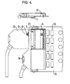
- Fig. 4 shows a specific application.
- the printed circuit board 24, on which integrated components 25 are applied contains two female connectors 14 with corresponding air cover brackets 26.
- the lower cable connector is drawn in and the upper cable connector 27 is drawn.
- FIG. 4 the cross section of a plug which is in the inserted state can be seen, the locking lugs 5 on the base part 1 of the line plug 27 being clearly visible.
Abstract
Description
Die Erfindung betrifft einen Leitungsstecker für parallele optische Datenübertragung mit einem Bodenteil mit Seitenwänden,einem auf dieses aufrastbaren Deckel und mindestens einer Einführungsöffnung für ein Lichtwellenleiterkabel.The invention relates to a line connector for parallel optical data transmission with a base part with side walls, a cover which can be snapped onto this and at least one insertion opening for an optical fiber cable.
In den-meisten Datenübertragungsanlagen wird bisher das Standard-Interface, bei dem bis zu 38 Signale parallel übertragen werden müssen, mit elektrischen Leitern aufgebaut. Immer mehr werden jedoch auch Lichtwellenleiter in der Datentechnik verwendet. Bekannte Ausführungen haben aber den Nachteil, daß die Ankoppelelemente Glasfaser-Diode meistens als Stecker mit optischer Trennung ausgeführt sind.. Um bei mehreren Steckungen reproduzierbare Übertragungswerte zu erhalten, sind diese Teile technisch sehr aufwendig und umfangreich.In most data transmission systems, the standard interface, in which up to 38 signals have to be transmitted in parallel, has so far been set up with electrical conductors. However, optical fibers are also increasingly being used in data technology. Known designs have the disadvantage, however, that the coupling elements of the glass fiber diode are mostly designed as plugs with optical isolation. In order to obtain reproducible transmission values in the case of several plugs, these parts are technically very complex and extensive.
Aufgabe der vorliegenden Erfindung ist es daher, einen Leitungsstecker für parallele optische Datenübertragung mit optischem Kabeleingang und elektrischem Steckausgang zu schaffen.The object of the present invention is therefore to create a line connector for parallel optical data transmission with an optical cable input and an electrical plug output.
Zur Lösung dieser Aufgabe wird der Leitungsstecker derart ausgebildet, daß das in seinem Steckbereich rechteckförmig und im Kabelzuführungsbereich trapezförmig auslaufend ausgebildete Bodenteil an den drei Trapezseiten Öffnungen aufweist, in die bedarfsweise zylindrisch ausgebildete, zum Steckerinneren zu sich aufweitende Einführtrichter einsetzbar sind, und daß im Steckbereich mehrere, für die optoelektrische Umsetzung ausgebildete Steckermodule nebeneinander angeordnet sind, die rückseitig jeweils mit einzelnen Leitern des Lichtwellenleiterkabels verbunden sind und an der Vorderseite Kontaktstifte für " eine elektrische Steckung enthalten.To solve this problem, the cable connector is designed such that the bottom part, which is rectangular in its plug-in area and trapezoidal in the cable feed area, has openings on the three trapezoid sides into which, if necessary, cylindrical insertion funnels which expand towards the inside of the plug can be used, and that several are inserted in the plug-in area , plug modules designed for optoelectrical implementation are arranged next to one another, each of which is connected on the back to individual conductors of the optical waveguide cable and has contact pins on the front for " contain an electrical plug.
Durch diese Maßnahmen erhält man einen Leitungsstecker für optoelektrische Datenübertragung, bei dem die Steckung auf der elektrischen Seite vorgenommen wird. Durch die Aneinanderreihung von Einzelsteckmoduln für die optoelektrische Umsetzung kann ein Steckerfeld geschaffen werden, das den bisherigen elektrischen Steckern angepaßt ist, so daß das bisherige elektrische Interface durch ein optoelektronisches ohne großen Umrüstaufwand ausgetauscht werden kann. Die Lichtwellenleiterzuführung kann je nach Platzbedarf von hinten, von oben oder von unten erfolgen.These measures result in a cable plug for optoelectric data transmission, in which the plugging is carried out on the electrical side. By lining up individual plug-in modules for the opto-electrical implementation, a connector field can be created which is adapted to the previous electrical plugs, so that the previous electrical interface can be replaced by an opto-electronic one without major conversion effort. The optical fiber can be fed in from behind, from above or from below, depending on the space required.
Bildet man dabei den Leitungsstecker derart aus, daß die an den schrägen Seiten des hinteren Bodenteils einsetzbaren Einführtrichter zu den Steckerseitenwänden hin mit einer verlängerten, den minimal zulässigen Biegeradius der einzelnen Lichtwellenleiter nicht unterschreitenden Trichterseitenwand versehen sind, so ist stets sichergestellt daß der kleinste zulässige Biegeradius des einzelnen Lichtwellenleiters nicht unterschritten wird, so daß die Übertragungseigenschaften des Lichtwellenleiters auch bei längerem Gebrauch erhalten bleiben.If the cable connector is designed in such a way that the insertion funnels that can be used on the inclined sides of the rear base part are provided with an extended funnel side wall that does not fall below the minimum permissible bending radius of the individual optical waveguides, it is always ensured that the smallest permissible bending radius of the individual optical waveguide is not undercut, so that the transmission properties of the optical waveguide are retained even after prolonged use.
Je nach Verwendungsfall können die Einführtrichter in den unterschiedlichen Einführüffnungen eingerastet werden. Hierfür sieht die Erfindung vor, daß die Einführtrichter mit einem Flansch versehen sind, der in Ausnehmungen des Bodenteils einsetzbar ist. Zur Abstützung der verlängernden Seitenwand der seitlichen Einführtrichter ist ein senkrecht zum Bodenteil verlaufender Zapfen vorgesehen, der sich sowohl am Bodenteil als auch an dem später aufbringbaren Deckel abstützt und dadurch entlastend wirkt.Depending on the application, the insertion funnels can be snapped into the different insertion openings. For this purpose, the invention provides that the insertion funnels are provided with a flange which can be used in recesses in the base part. To support the lengthening side wall of the side insertion funnels, a pin running perpendicular to the bottom part is provided, which is supported both on the bottom part and on the cover that can be attached later and thus has a relieving effect.
Eine Zugentlastung für das angeschlossene Lichtwellenleiterkabel kann dadurch gebildet werden, daß der die Kabelseele bildende Stahldraht mittels einer Öse an einen Zapfen in der Steckermitte eingehängt wird. Eine andere Möglichkeit besteht darin, daß das Lichtwellenleiterkabel nach Einführen in den Einführtrichter mit diesen vergossen wird.A strain relief for the connected light waves Conductor cable can be formed by hanging the steel wire forming the cable core by means of an eyelet on a pin in the center of the connector. Another possibility is that the optical waveguide cable is cast with it after insertion into the insertion funnel.
Das Bodenteil kann außerdem Aussparungen enthalten, in die am Deckel senkrecht zu ihm angebrachte Fortsätze mit Nasen einrasten.The base part can also contain recesses into which projections with lugs snap vertically to the cover.
Um den Einführtrichter auch nach vorne zu fixieren, sind im Bodenteil hinter den Ausnehmungen für den Flansch der seitlichen Einführtrichter je ein Steg vorgesehen, der mit dem Flansch und dem verlängerten Trichterseitenteil in Eingriff steht.In order to fix the insertion funnel also to the front, a web is provided in the bottom part behind the recesses for the flange of the lateral insertion funnel, which engages with the flange and the extended funnel side part.
Die nicht benützten Öffnungen für die Einführtrichter können mit Abdeckteilen verschlossen werden.The unused openings for the insertion funnels can be closed with cover parts.
Zum Schutz der Kontaktstifte im Steckerteil des Leitungssteckers kann das Bodenteil und der Deckel so weit verlängert sein, daß sie einen Schutzkragen um die Kontaktstifte bilden.To protect the contact pins in the plug part of the line connector, the base part and the cover can be extended so far that they form a protective collar around the contact pins.
Um beispielsweise unterschiedliche Längen ausglechen zu können, kann neben dem optoelektronischen Steckmoduln mindestens ein weiteres Modul zur Aufnahme einer Kompensationsschaltung vorgesehen sein. Im einfachsten Fall handelt es sich dabei um einen entsprechend dimensionierten Ohmschen Widerstand.In order to be able to compensate for different lengths, for example, in addition to the optoelectronic plug-in modules, at least one further module can be provided for receiving a compensation circuit. In the simplest case, this is a correspondingly dimensioned ohmic resistance.
Um auch bei Platzmangel den Leitungsstecker ziehen zu können, sind neben der Öffnung für den mittleren Einführtrichter im Bodenteil Löcher zum Ansatz eines Ziehwerkzeuges vorgesehen.In order to be able to pull the cable connector even when there is not enough space, holes are provided in addition to the opening for the middle insertion funnel in the base part for attaching a pulling tool.
Zum Einrasten und Verriegeln des Leitungssteckers mit der im allgemeinen auf einer Leiterplatte befindlichen Fassung sind an der Unterseite Nasen vorgesehen, die in Aussparungen 5 der zugehörigen Fassung einrasten.To lock and lock the cable connector with the socket, which is generally located on a printed circuit board, lugs are provided on the underside, which snap into
Anhand der Ausführungsbeispiele nach den Figuren 1 bis 4 wird die Erfindung näher erläutert.The invention is explained in more detail using the exemplary embodiments according to FIGS. 1 to 4.
Dabei zeigen die
- Fig. 1 zwei untereinander angeordnete Leitungsstecker, von denen der eine teils im Schnitt, teils in Draufsicht ohne Deckel gezeichnet ist,
- Fig. 2 einen Querschnitt des Leitungssteckers im Bereich der für die Deckeleinrastung vorgesehenen Ausnehmungen,
- Fig. 3 eine Rückansicht des Leitungssteckers und
- Fig. 4 ein Einsatzbeispiel bei einer in einer Datenverarbeitungsanlage befindlichen elektrischen Leiterplatte.
- 1 two line connectors arranged one below the other, one of which is drawn partly in section, partly in plan view without a cover,
- 2 shows a cross section of the line plug in the region of the recesses provided for the cover latching,
- Fig. 3 is a rear view of the line connector and
- Fig. 4 shows an example of use in an electrical circuit board located in a data processing system.
Der Leitungsstecker in.der Fig. 1 besteht aus einem Bodenteil mit Seitenwänden 1, einem Deckel 2, einem Einführtrichter 7, den Umsetzerbausteinen 3 und evtl. einem Kompensationsbaustein 4. Außerdem bringt er die Verriegelung 5 mit oder jeweils zugehörigen Flachbaugruppe und die Zugentlastung für das Glasfaserkabel mit. Es besteht die Möglichkeit, das Kabel nach oben a, unten b oder nach hinten c wegzuführen. Im Stecker ist Raum genug, um die Einzelfasern unter Einhaltung des Mindestbiegeradius an die Umsetzerbausteine anschließen zu können. Die Kabeleinführung und Abfangung des Kabelmantels 6 geschieht durch Einführtrichter 7. Der Einführtrichter für die Kabelausführung nach oben und unten ist das gleiche Bauteil und kann auf Umschlag verwendet werden. Die jeweils ersten Einzelfasern liegen an einer verlängerten Seitenwand 8 des Trichters an; auf diese Weise wird eine Unterschreitung des Mindestbiegeradius vermieden. Die eigentliche1 consists of a bottom part with side walls 1, a
Zugentlastung des zwanzigadrigen Kabels erfolgt dadurch, daß der Stahldraht 9, der die Seele des Kabels bildet, mittels einer Öse an einem Zapfen 10 in der Steckermitte eingehängt wird oder die Einzelfeder im Trichter eingegossen werden.The 20-wire cable is relieved of strain by hanging the steel wire 9, which forms the core of the cable, by means of an eyelet on a
Als Umsetzerbausteine kommen hauptsächlich Quadromodul-Bausteine, wie sie in der deutschen Patentanmeldung P...(VPA 81P2026) beschrieben sind, in Frage. Wie aus dieser Patentanmeldung hervorgeht, sind in einem Umsetzerbaustein 4 Sendedioden bzw. 4 Empfangsdioden mit Verstärkerschaltung enthalten. Stirnseitig sind 8 Anschlußbeinchen, die als Kontaktstifte 12 ausgebildet sind, zweireihig in einem vorgegebenen Raster angeordnet. Im Leitungsstecker können maximal fünf Modulbausteine und ein Kompensationsbaustein mit zwei Anschlußstiften 12 angeordnet werden, so daß sich die Stifte zu einer 2 x 21 = 42-poligen Stiftleiste 12 zusammenfügen.Quadromodule modules, as described in German patent application P ... (VPA 81P2026), are mainly used as converter modules. As is apparent from this patent application, 4 transmitter diodes or 4 receive diodes with amplifier circuit are contained in a converter module. On the face side, 8 connecting legs, which are designed as
Der Boden und der Deckel des Leitungssteckers sind so weit vorgezogen, daß die Stifte zwischen diesen Schutzwänden 13 liegen und vor einer Beschädigung, besonders bei gezogenem Stecker, geschützt sind. Die Federleiste 14 auf der Flachbaugruppe wird auf Stützen angeordnet. Damit der Quadromodulbaustein und der Kompensationsbaustein beim Steck- und Ziehvorgang ihre Lage im Stecker nicht verändern können, sind sie mit Haltenasen 15 ausgestattet, welche in Aussparungen eingreifen, die im Bodenteil und im Deckel im Rasterteilungsabstand vorhanden sind. Der Deckel des Leitungssteckers hat zwei zur Deckelfläche rechtwinklige Fortsätze mit Nasen 16, welche beim Anbringen des Deckels in entsprechenden Aussparungen des Bodenteils 17 verrasten. Zum Abnehmen werden die Fortsätze entgegen ihrer Federwirkung nach innen gedrückt, bis die formschlüssige Verbindung nicht mehr besteht.The bottom and the cover of the line connector are so far advanced that the pins lie between these
Zum Ziehen des Leitungssteckers muß bei verschiedenen Einbaufällen ein Werkzeug verwendet werden. Dieses wird in zwei Löcher 18 am Hinterende des Leitungssteckers eingesetzt. Es dient gewissermaßen als Steckerverlängerung.A tool must be used to pull out the cable connector in various installation cases. This is in two
Fig. 2 zeigt einen Schnitt etwa in . der Höhe der Ausnehmungen 17 durch den Leitungsstecker mit aufgerastertem Deckel 2. Am Deckel befinden sich senkrechte Ansätze 16, die in entsprechende Nasen auslaufen, die in Ausnehmungen 17 des Bodenteiles 1 eingreifen. An die fünf optoelektronischen Steckmodule 3 sind die Einzelfasern 19 des Lichtwellenleiterkabels 11 geführt.Fig. 2 shows a section approximately in. the height of the
In der Draufsicht nach' Fig. 3 ist eine Ausführung zu ersehen, bei der das Lichtleiterwellenkabel 7 von unten her an den Stecker herangeführt wird. Die mittlere und obere Öffnung sind frei und können entsprechend mit einem Abdeckteil abgedeckt werden.In the top view according to FIG. 3, an embodiment can be seen in which the
Fig. 4 zeigt einen konkreten Einsatzfall. Die Leiterplatte 24,auf der integrierte Bauteile 25 aufgebracht sind, enthält zwei Federleisten 14 mit entsprechenden Luftabdeckwinkeln 26. Auf den Luftabdeckwinkeln 26 befinden sich Aussparungen 5, in die im Bodenteil 1 des Leitungssteckers 27 in der Zeichnung nicht sichtbare Rastnasen beim Einstecken des Leitungssteckers 27 in die Fassung eingreifen. Der untere Leitungsstecker ist im eingesteckten und der obere Leitungsstecker 27 im gezogenen Zustand gezeichnet. Oberhalb der Fig. 4 ist der Querschnitt eines im gesteckten Zustand befindlichen Steckers zu sehen, wobei die Rastnasen 5 am Bodenteil 1 des Leitungssteckers 27 deutlich sichtbar sind.Fig. 4 shows a specific application. The printed
Claims (13)
Applications Claiming Priority (2)
| Application Number | Priority Date | Filing Date | Title |
|---|---|---|---|
| DE3113168 | 1981-04-01 | ||
| DE3113168A DE3113168C2 (en) | 1981-04-01 | 1981-04-01 | Line connector for parallel optical data transmission |
Publications (3)
| Publication Number | Publication Date |
|---|---|
| EP0062287A2 true EP0062287A2 (en) | 1982-10-13 |
| EP0062287A3 EP0062287A3 (en) | 1982-12-08 |
| EP0062287B1 EP0062287B1 (en) | 1985-07-24 |
Family
ID=6129065
Family Applications (1)
| Application Number | Title | Priority Date | Filing Date |
|---|---|---|---|
| EP82102679A Expired EP0062287B1 (en) | 1981-04-01 | 1982-03-30 | Plug for parallel transmission of optical data |
Country Status (3)
| Country | Link |
|---|---|
| EP (1) | EP0062287B1 (en) |
| JP (1) | JPS6041326B2 (en) |
| DE (1) | DE3113168C2 (en) |
Cited By (6)
| Publication number | Priority date | Publication date | Assignee | Title |
|---|---|---|---|---|
| DE3302373A1 (en) * | 1983-01-25 | 1984-07-26 | WAGO Verwaltungsgesellschaft mbH, 4950 Minden | Switching installation terminal block |
| EP0201749A2 (en) * | 1985-05-14 | 1986-11-20 | Allied Corporation | Contact with exchangeable opto-electronic element |
| EP0677756A2 (en) * | 1994-04-13 | 1995-10-18 | Framatome Connectors International | Combined beam waveguide and metal cable plug connector |
| EP1180704A2 (en) * | 2000-08-09 | 2002-02-20 | Siemens Aktiengesellschaft | Connector and system for electrical connection of rack assembly in the area of telecommunications |
| WO2006047190A1 (en) * | 2004-10-22 | 2006-05-04 | Intel Corporation | Surface mount (smt) connector for vcsel and photodiode arrays |
| CN108716961A (en) * | 2018-06-21 | 2018-10-30 | 迈格仪表(成都)有限公司 | A kind of pressure transmitter |
Families Citing this family (9)
| Publication number | Priority date | Publication date | Assignee | Title |
|---|---|---|---|---|
| DE3524430A1 (en) * | 1985-07-09 | 1987-01-22 | Albatron Elektronik Gmbh | Device for connecting the interfaces, in particular of the V24 type, of independent switching devices of data processing systems |
| DE9001896U1 (en) * | 1990-02-17 | 1991-06-13 | Stribel Gmbh, 7443 Frickenhausen, De | |
| DE59106807D1 (en) * | 1990-02-17 | 1995-12-07 | Stribel Gmbh | SIGNAL TRANSMISSION LINE. |
| DE9215027U1 (en) * | 1992-11-09 | 1993-01-14 | Inotec Electronics Gmbh, 7100 Heilbronn, De | |
| DE4338732C2 (en) * | 1993-11-12 | 2003-12-11 | Thomas Dandekar | Biosensor (new design) |
| DE4443200C1 (en) * | 1994-12-05 | 1996-06-20 | Framatome Connectors Int | Combined optical fibre cable and metal cable plug connector |
| DE10018018A1 (en) * | 2000-04-11 | 2001-10-25 | Delphi Tech Inc | Plug connector for optical fiber cable, incorporates aligned electro-optical converter connected directly to optical cable |
| DE10217579A1 (en) * | 2002-04-19 | 2003-11-13 | Xignal Technologies Ag | Data transfer cable has electrooptical converter for converting between electrical, optical signals electrically connected to electrical plug connector, optically connected to light waveguide in cable |
| CN106991108A (en) | 2016-09-27 | 2017-07-28 | 阿里巴巴集团控股有限公司 | The method for pushing and device of a kind of information |
Citations (6)
| Publication number | Priority date | Publication date | Assignee | Title |
|---|---|---|---|---|
| FR973130A (en) * | 1941-06-20 | 1951-02-07 | Jaeger Ets Ed | Improvements to multiple electrical connection devices |
| US2891132A (en) * | 1955-12-13 | 1959-06-16 | Columbus Mckinnon Chain Corp | Electric hoist control |
| GB979826A (en) * | 1962-06-21 | 1965-01-06 | United Carr Inc | Electrical plug unit |
| DE2013884A1 (en) * | 1970-03-23 | 1971-10-21 | Siemens Ag | Plug-in device |
| DE1790336A1 (en) * | 1967-02-07 | 1976-04-22 | Bunker Ramo | ELECTRIC CONNECTION FITTINGS |
| DE2824009A1 (en) * | 1978-06-01 | 1979-12-06 | Harting Elektronik Gmbh | Plug connector with tension absorption clip in grip - has openings with slot for strap and cap for inserted cable |
Family Cites Families (1)
| Publication number | Priority date | Publication date | Assignee | Title |
|---|---|---|---|---|
| DE3008255A1 (en) * | 1979-03-07 | 1980-09-11 | Vero Electronics Ltd | END CONNECTOR FOR AN OPTICAL FIBER CABLE |
-
1981
- 1981-04-01 DE DE3113168A patent/DE3113168C2/en not_active Expired
-
1982
- 1982-03-30 EP EP82102679A patent/EP0062287B1/en not_active Expired
- 1982-04-01 JP JP57054751A patent/JPS6041326B2/en not_active Expired
Patent Citations (6)
| Publication number | Priority date | Publication date | Assignee | Title |
|---|---|---|---|---|
| FR973130A (en) * | 1941-06-20 | 1951-02-07 | Jaeger Ets Ed | Improvements to multiple electrical connection devices |
| US2891132A (en) * | 1955-12-13 | 1959-06-16 | Columbus Mckinnon Chain Corp | Electric hoist control |
| GB979826A (en) * | 1962-06-21 | 1965-01-06 | United Carr Inc | Electrical plug unit |
| DE1790336A1 (en) * | 1967-02-07 | 1976-04-22 | Bunker Ramo | ELECTRIC CONNECTION FITTINGS |
| DE2013884A1 (en) * | 1970-03-23 | 1971-10-21 | Siemens Ag | Plug-in device |
| DE2824009A1 (en) * | 1978-06-01 | 1979-12-06 | Harting Elektronik Gmbh | Plug connector with tension absorption clip in grip - has openings with slot for strap and cap for inserted cable |
Non-Patent Citations (2)
| Title |
|---|
| ELECTRONICS, Band 49, Nr. 18, 2. September 1976, Seiten 94-99, New York, USA; H. SCHMID: "Fiber-optic data transmission: a practical, low-cost technology". * |
| ELEKTROTECHNIK, Band 55, Nr. 11, 14. Juni 1973, Seite 5, Berlin, DE; "neues Kabelsteckergehäuse-Programm". * |
Cited By (11)
| Publication number | Priority date | Publication date | Assignee | Title |
|---|---|---|---|---|
| DE3302373A1 (en) * | 1983-01-25 | 1984-07-26 | WAGO Verwaltungsgesellschaft mbH, 4950 Minden | Switching installation terminal block |
| EP0201749A2 (en) * | 1985-05-14 | 1986-11-20 | Allied Corporation | Contact with exchangeable opto-electronic element |
| EP0201749A3 (en) * | 1985-05-14 | 1987-04-22 | Allied Corporation | Contact with exchangeable opto-electronic element |
| US4779948A (en) * | 1985-05-14 | 1988-10-25 | Amphenol Corporation | Contact with exchangeable opto-electronic element |
| EP0677756A2 (en) * | 1994-04-13 | 1995-10-18 | Framatome Connectors International | Combined beam waveguide and metal cable plug connector |
| EP0677756A3 (en) * | 1994-04-13 | 1996-05-01 | Framatome Connectors Int | Combined beam waveguide and metal cable plug connector. |
| EP1180704A2 (en) * | 2000-08-09 | 2002-02-20 | Siemens Aktiengesellschaft | Connector and system for electrical connection of rack assembly in the area of telecommunications |
| EP1180704A3 (en) * | 2000-08-09 | 2003-08-20 | Siemens Aktiengesellschaft | Connector and system for electrical connection of rack assembly in the area of telecommunications |
| WO2006047190A1 (en) * | 2004-10-22 | 2006-05-04 | Intel Corporation | Surface mount (smt) connector for vcsel and photodiode arrays |
| US8412052B2 (en) | 2004-10-22 | 2013-04-02 | Intel Corporation | Surface mount (SMT) connector for VCSEL and photodiode arrays |
| CN108716961A (en) * | 2018-06-21 | 2018-10-30 | 迈格仪表(成都)有限公司 | A kind of pressure transmitter |
Also Published As
| Publication number | Publication date |
|---|---|
| EP0062287A3 (en) | 1982-12-08 |
| JPS57177114A (en) | 1982-10-30 |
| JPS6041326B2 (en) | 1985-09-17 |
| DE3113168A1 (en) | 1982-10-14 |
| EP0062287B1 (en) | 1985-07-24 |
| DE3113168C2 (en) | 1985-09-12 |
Similar Documents
| Publication | Publication Date | Title |
|---|---|---|
| EP0062287B1 (en) | Plug for parallel transmission of optical data | |
| DE69735414T2 (en) | MODULAR SOCKET WITH REDUCED OVERRIDE | |
| DE69930083T2 (en) | Connector for communication cables | |
| DE112009000065B4 (en) | harness | |
| DE112016000539B4 (en) | Communication connector | |
| DE4402837A1 (en) | Flat cable | |
| EP2656448A2 (en) | Connector for high data transmission rates | |
| DE102017219078A1 (en) | Branch structure and wire harness | |
| DE112015001539T5 (en) | Connection structure of a connector and connector | |
| EP0061772A1 (en) | Electro-optical plug-connector module | |
| DE69931091T2 (en) | Electrical connector device | |
| EP0849840B1 (en) | Multipole screened cable connector | |
| DE8016071U1 (en) | TRANSITION CONNECTION FOR COAXIAL CABLES | |
| DE102019212751A1 (en) | Wiring harness | |
| DE8413226U1 (en) | Diode connector | |
| DE60223619T2 (en) | Plug device and plug | |
| DE3537432C2 (en) | ||
| DE2620267A1 (en) | Three tier edge connector for printed circuit board - has slot at front for engaging board at centre and screened leads in outer tiers | |
| DE102011089025B4 (en) | USB socket and method for its manufacture | |
| AT503637B1 (en) | CABLE WITH CONNECTOR, CONNECTOR FOR A CABLE AND METHOD FOR CONNECTING A CABLE WITH A CONNECTOR | |
| EP0584658A2 (en) | Distributor for EMI shielded cabinets | |
| DE102019129589A1 (en) | CABLE CONNECTORS | |
| DE102020123465B4 (en) | Optoelectronic module, optoelectronic connector and optoelectronic sub-distribution | |
| DE60104287T2 (en) | Connector for a communications network cable | |
| EP0498342B1 (en) | Connection device under application of an outlet |
Legal Events
| Date | Code | Title | Description |
|---|---|---|---|
| PUAI | Public reference made under article 153(3) epc to a published international application that has entered the european phase |
Free format text: ORIGINAL CODE: 0009012 |
|
| PUAL | Search report despatched |
Free format text: ORIGINAL CODE: 0009013 |
|
| AK | Designated contracting states |
Designated state(s): FR GB IT NL |
|
| AK | Designated contracting states |
Designated state(s): FR GB IT NL |
|
| 17P | Request for examination filed |
Effective date: 19821206 |
|
| ITF | It: translation for a ep patent filed |
Owner name: STUDIO JAUMANN |
|
| GRAA | (expected) grant |
Free format text: ORIGINAL CODE: 0009210 |
|
| AK | Designated contracting states |
Designated state(s): FR GB IT NL |
|
| ET | Fr: translation filed | ||
| PGFP | Annual fee paid to national office [announced via postgrant information from national office to epo] |
Ref country code: NL Payment date: 19860331 Year of fee payment: 5 |
|
| PLBE | No opposition filed within time limit |
Free format text: ORIGINAL CODE: 0009261 |
|
| STAA | Information on the status of an ep patent application or granted ep patent |
Free format text: STATUS: NO OPPOSITION FILED WITHIN TIME LIMIT |
|
| 26N | No opposition filed | ||
| PG25 | Lapsed in a contracting state [announced via postgrant information from national office to epo] |
Ref country code: NL Effective date: 19871001 |
|
| NLV4 | Nl: lapsed or anulled due to non-payment of the annual fee | ||
| GBPC | Gb: european patent ceased through non-payment of renewal fee | ||
| PG25 | Lapsed in a contracting state [announced via postgrant information from national office to epo] |
Ref country code: FR Free format text: LAPSE BECAUSE OF NON-PAYMENT OF DUE FEES Effective date: 19871130 |
|
| REG | Reference to a national code |
Ref country code: FR Ref legal event code: ST |
|
| PG25 | Lapsed in a contracting state [announced via postgrant information from national office to epo] |
Ref country code: GB Effective date: 19881121 |