EP0061979A1 - Injection system with pilot-operated injector for an internal combustion engine - Google Patents
Injection system with pilot-operated injector for an internal combustion engine Download PDFInfo
- Publication number
- EP0061979A1 EP0061979A1 EP82420032A EP82420032A EP0061979A1 EP 0061979 A1 EP0061979 A1 EP 0061979A1 EP 82420032 A EP82420032 A EP 82420032A EP 82420032 A EP82420032 A EP 82420032A EP 0061979 A1 EP0061979 A1 EP 0061979A1
- Authority
- EP
- European Patent Office
- Prior art keywords
- chamber
- injector
- piston
- needle
- pressure
- Prior art date
- Legal status (The legal status is an assumption and is not a legal conclusion. Google has not performed a legal analysis and makes no representation as to the accuracy of the status listed.)
- Granted
Links
Images

Classifications
-
- F—MECHANICAL ENGINEERING; LIGHTING; HEATING; WEAPONS; BLASTING
- F02—COMBUSTION ENGINES; HOT-GAS OR COMBUSTION-PRODUCT ENGINE PLANTS
- F02M—SUPPLYING COMBUSTION ENGINES IN GENERAL WITH COMBUSTIBLE MIXTURES OR CONSTITUENTS THEREOF
- F02M47/00—Fuel-injection apparatus operated cyclically with fuel-injection valves actuated by fluid pressure
- F02M47/02—Fuel-injection apparatus operated cyclically with fuel-injection valves actuated by fluid pressure of accumulator-injector type, i.e. having fuel pressure of accumulator tending to open, and fuel pressure in other chamber tending to close, injection valves and having means for periodically releasing that closing pressure
-
- F—MECHANICAL ENGINEERING; LIGHTING; HEATING; WEAPONS; BLASTING
- F02—COMBUSTION ENGINES; HOT-GAS OR COMBUSTION-PRODUCT ENGINE PLANTS
- F02M—SUPPLYING COMBUSTION ENGINES IN GENERAL WITH COMBUSTIBLE MIXTURES OR CONSTITUENTS THEREOF
- F02M63/00—Other fuel-injection apparatus having pertinent characteristics not provided for in groups F02M39/00 - F02M57/00 or F02M67/00; Details, component parts, or accessories of fuel-injection apparatus, not provided for in, or of interest apart from, the apparatus of groups F02M39/00 - F02M61/00 or F02M67/00; Combination of fuel pump with other devices, e.g. lubricating oil pump
- F02M63/02—Fuel-injection apparatus having several injectors fed by a common pumping element, or having several pumping elements feeding a common injector; Fuel-injection apparatus having provisions for cutting-out pumps, pumping elements, or injectors; Fuel-injection apparatus having provisions for variably interconnecting pumping elements and injectors alternatively
- F02M63/0205—Fuel-injection apparatus having several injectors fed by a common pumping element, or having several pumping elements feeding a common injector; Fuel-injection apparatus having provisions for cutting-out pumps, pumping elements, or injectors; Fuel-injection apparatus having provisions for variably interconnecting pumping elements and injectors alternatively for cutting-out pumps or injectors in case of abnormal operation of the engine or the injection apparatus, e.g. over-speed, break-down of fuel pumps or injectors ; for cutting-out pumps for stopping the engine
-
- F—MECHANICAL ENGINEERING; LIGHTING; HEATING; WEAPONS; BLASTING
- F02—COMBUSTION ENGINES; HOT-GAS OR COMBUSTION-PRODUCT ENGINE PLANTS
- F02B—INTERNAL-COMBUSTION PISTON ENGINES; COMBUSTION ENGINES IN GENERAL
- F02B1/00—Engines characterised by fuel-air mixture compression
- F02B1/02—Engines characterised by fuel-air mixture compression with positive ignition
- F02B1/04—Engines characterised by fuel-air mixture compression with positive ignition with fuel-air mixture admission into cylinder
-
- F—MECHANICAL ENGINEERING; LIGHTING; HEATING; WEAPONS; BLASTING
- F02—COMBUSTION ENGINES; HOT-GAS OR COMBUSTION-PRODUCT ENGINE PLANTS
- F02B—INTERNAL-COMBUSTION PISTON ENGINES; COMBUSTION ENGINES IN GENERAL
- F02B75/00—Other engines
- F02B75/12—Other methods of operation
- F02B2075/125—Direct injection in the combustion chamber for spark ignition engines, i.e. not in pre-combustion chamber
-
- F—MECHANICAL ENGINEERING; LIGHTING; HEATING; WEAPONS; BLASTING
- F02—COMBUSTION ENGINES; HOT-GAS OR COMBUSTION-PRODUCT ENGINE PLANTS
- F02B—INTERNAL-COMBUSTION PISTON ENGINES; COMBUSTION ENGINES IN GENERAL
- F02B3/00—Engines characterised by air compression and subsequent fuel addition
- F02B3/06—Engines characterised by air compression and subsequent fuel addition with compression ignition
-
- Y—GENERAL TAGGING OF NEW TECHNOLOGICAL DEVELOPMENTS; GENERAL TAGGING OF CROSS-SECTIONAL TECHNOLOGIES SPANNING OVER SEVERAL SECTIONS OF THE IPC; TECHNICAL SUBJECTS COVERED BY FORMER USPC CROSS-REFERENCE ART COLLECTIONS [XRACs] AND DIGESTS
- Y02—TECHNOLOGIES OR APPLICATIONS FOR MITIGATION OR ADAPTATION AGAINST CLIMATE CHANGE
- Y02T—CLIMATE CHANGE MITIGATION TECHNOLOGIES RELATED TO TRANSPORTATION
- Y02T10/00—Road transport of goods or passengers
- Y02T10/10—Internal combustion engine [ICE] based vehicles
- Y02T10/12—Improving ICE efficiencies
Definitions
- the present invention relates to an injection system intended to equip an internal combustion engine. It is known that the purpose of the injection system is to dose a liquid fuel (in particular a hydrocarbon) before sending it under pressure to an injector.
- a liquid fuel in particular a hydrocarbon
- each combustion chamber is equipped with an injector provided with a shutter needle, which lifts at the start of each injection, to close on his seat as soon as the injection is finished.
- the injector needle is subjected to the thrust of a spring which tends to push it back onto its seat, that is to say to return it to the closed position.
- the pressure wave causes the injector needle to rise.
- the return spring tends to close the needle, and it effectively closes it most of the time.
- the needle tends to seize up in the injector body, so that the spring return thrust becomes insufficient to close the needle. Communication then remains established between the body of the injector holder and the combustion chamber, which has the result of causing the engine to break down more or less quickly. This drawback is particularly serious in the case of an injection system with constant pressure supply, because then the open seized injector continuously delivers fuel.
- the object of the present invention is to avoid this drawback by providing a safety system which automatically cuts off the supply of an injector when the latter remains seized in the open position.
- a safety device intended to equip the injector with an internal combustion engine provided with a needle normally driven by a lifting and falling movement, respectively at the start and at the end of each injection, while supply piping supplies the injector with liquid fuel at the supply pressure, and characterized in that dispensing means receiving the fuel at the supply pressure are provided on a part integral with the injector needle 4 to move in front a fixed orifice of the injector holder 1 which communicates with a chamber 13 with an obturator piston to admit fuel therein through the dispensing means when the injector needle is in the open position, this piston chamber being equipped with a sliding differential piston 13,14 which, when the pressure in its chamber 13 reaches a predetermined threshold, moves to close off the general supply of the injector 2, timed pressure establishment means being finally provided on the chamber 13 the shutter piston.
- the injector needle lifts pressurized fuel begins to enter the chamber of the shutter piston. If this admission does not exceed a predetermined duration, defined by the delay means, the pressure in the chamber of the shutter piston never exceeds its triggering threshold, and nothing happens: the injection is carried out normally, and it ceases as soon as the needle closes.
- the duration threshold defined by the timing means is chosen for a time greater than the duration of the longest injections planned for the system, in order not to hinder in any way a normal injection process.
- the injector needle tends to remain seized in the open position
- the duration increases during which pressurized fuel is admitted into the chamber of the obturator piston.
- the pressure becomes sufficient behind the obturator piston to move it and automatically come to cut the supply of the injector out of order. This cutoff is maintained as long as the injector needle remains seized in the open position. This avoids any serious deterioration of the engine.
- the timer means are constituted by a calibrated orifice equipping the chamber of the shutter piston, to connect it to the fuel discharge circuit.
- the chamber of this shutter piston is therefore supplied through a section orifice S of the dispensing means, and it is connected to the discharge by a section orifice s. It suffices to calculate the relative values of the supply and discharge sections S to define the pressure which builds up behind the obturator piston in the case of a permanent flow, that is to say when the needle of the injector is seized open.
- an injector 2 Inside the injector holder 1 is in the known manner an injector 2, the end of which includes injection 3.
- a sealing seat not shown, on which the end of an injector needle 4 can come in known manner.
- the tail 5 of the injector needle 4 receives an end piece 6 behind which bears a calibrated return spring 7.
- the end piece 6 is part of a pusher 8 which, according to the invention, has a rear cylindrical part 9 playing the role of a hydraulic distributor.
- the needle 4 lifts with each injection and the result for the drawer 9 is an alternating sliding movement in a stationary distributor body 10.
- the clearance between the drawer 9 and the body 10 corresponds to tolerances common machining operations on injection systems, to ensure satisfactory sealing of the combustible liquid when the latter is at the usual pressure,
- the dispenser drawer 9 has a groove ll which is capable of moving in front of a fixed orifice 12 which has a passage section of value S.
- This orifice 12 is formed in the body 10 and it communicates with a cylindrical chamber 13 in which can slide sealingly a differential piston comprising a large section 14 and a small section 15.
- the large section body 14 of this piston 14, 15 slides in the cylindrical chamber 13 between a return spring 16 and an antagonistic thrust coming from the fuel admitted by orifice 12.
- the small section 15 is that of a cylindrical rod sliding in leaktight manner in a fixed cylindrical bore 19.
- the latter is arranged across a supply channel 20 that the small section 15 is completely closed when the differential piston 15, 16 occupies the raised position illustrated in FIG. 5.
- a nozzle 21 with calibrated section also connects the chamber 13 to a discharge circuit, not shown, which returns the fuel to the tank.
- the chamber located around the return spring 16 is also connected by a leak orifice 22, to the discharge circuit returning the fuel to the tank.
- the channel 20 receives in the known manner the main flow of fuel from the high pressure pump of the injection circuit.
- This channel 20 communicates in the usual way by holes such as 23 provided in the body of the injector holder 1, with the injection chamber not shown which is behind the sealing seat, at the end of the needle 4, for injecting the fuel into the engine by the orifices 3, as soon as the needle 4 is raised.
- a bore 25 is provided on the rear of the distributor drawer 9 which places the groove 11 in communication with the axial bore 24.
- the set of two calibrated orifices 12 (section S) and 21 (section s) constitutes a timer means for the operation of which S is given a value greater than that. from s.
- the law of this rise in pressure in the chamber 13 in function of time can be defined at will by the initial choice of the relative value of sections S and s.
- the respective values of S and s are chosen so that the pressure build-up in the chamber 13 of the differential piston 14,15 is sufficiently slow not to become preponderant compared to the setting thrust of the spring 16, for a period of time. less equal to the longest possible duration of an injection according to the various possible engine operating conditions.
- the differential piston 14, 15 remains constantly stationary in the position illustrated in FIG. 4, as long as the needle 4 of the injector operates in a normal manner. Indeed, at each start of injection, the needle 4 is raised, the groove 11 comes into coincidence with the orifice 12, and the pressure begins to rise in the chamber 13. However, before this pressure has enough mounted to crush the spring 16 and move the obturator piston 14,15, the injection ended, and the needle 4 fell back on its seat, the groove 11 returning to the position of Figure 2, which cuts the 'supply of the orifice 12. The chamber 13 now ceasing to be supplied while the nozzle 21 connects it to the discharge, its pressure drops and the differential piston 14, 15, remains stationary.
- the rod with a small section 15 of the differential piston completely closes the pipe 20 ensuring the supply of the injector 2. Consequently, as long as the needle 4 remains open, the supply of fuel stop by the canalisa tions 20, 23. This eliminates the incident which, on a conventional engine, would have led the injector 2 to continuously deliver fuel to the engine.
Abstract
Description
La présente invention est relative à un système d'injection destiné à équiper un moteur à combustion interne. On sait que le système d'injection a pour but de doser un combustible liquide (notamment un hydrocarbure) avant de l'envoyer sous pression vers un injecteur.The present invention relates to an injection system intended to equip an internal combustion engine. It is known that the purpose of the injection system is to dose a liquid fuel (in particular a hydrocarbon) before sending it under pressure to an injector.
Dans les moteurs Diesel ainsi que dans les moteurs à essence du type dit "à injection directe", chaque chambre de combustion est équipée d'un injecteur muni d'une aiguille obturatrice, laquelle se soulève au début de chaque injection, pour se refermer sur son siège dès que l'injection est terminée.In diesel engines as well as in petrol engines of the so-called "direct injection" type, each combustion chamber is equipped with an injector provided with a shutter needle, which lifts at the start of each injection, to close on his seat as soon as the injection is finished.
La plupart du temps, l'aiguille de l'injecteur est soumise à la poussée d'un ressort qui tend à la repousser sur son siège, c'est-à-dire à la rappeler en position de fermeture. A chaque fois que la pompe d'injection, complétée ou non par un distributeur, envoie le combustible, l'onde de pression provoque le soulèvement de l'aiguille d'injecteur. Dès que la pression devient insuffisante en fin d'injection, le ressort de rappel tend à refermer l'aiguille, et il la referme effectivement la plupart du temps. Par contre, il peut arriver que l'aiguille ait tendance à gripper dans le corps d'injecteur, si bien que la poussée de rappel du ressort devient insuffisante pour refermer l'aiguille. La communication reste alors établie entre le corps du porte-injecteur et la chambre de combustion, ce qui a pour résultat de faire tomber le moteur en panne à plus ou moins brève échéance. Cet inconvénient est particulièrement grave dans le cas d'un système d'injection à alimentation à pression constante, car alors l'injecteur grippé ouvert débite du combustible en permanence.Most of the time, the injector needle is subjected to the thrust of a spring which tends to push it back onto its seat, that is to say to return it to the closed position. Each time the injection pump, whether or not supplemented by a distributor, sends the fuel, the pressure wave causes the injector needle to rise. As soon as the pressure becomes insufficient at the end of injection, the return spring tends to close the needle, and it effectively closes it most of the time. On the other hand, it may happen that the needle tends to seize up in the injector body, so that the spring return thrust becomes insufficient to close the needle. Communication then remains established between the body of the injector holder and the combustion chamber, which has the result of causing the engine to break down more or less quickly. This drawback is particularly serious in the case of an injection system with constant pressure supply, because then the open seized injector continuously delivers fuel.
La présente invention a pour but d'éviter cet inconvénient en réalisant un système de sécurité qui coupe automatiquement l'alimentation d'un injecteur lorsque celui-ci reste grippé en position d'ouverture.The object of the present invention is to avoid this drawback by providing a safety system which automatically cuts off the supply of an injector when the latter remains seized in the open position.
Un dispositif de sécurité selon l'invention, destiné à équiper l'injecteur d'un moteur à combustion interne pourvu d' une aiguille normalement animée d'un mouvement de soulèvement et de retombée, respectivement au début et à la fin de chaque injection, tandis qu'une tuyauterie d'alimentation alimente l'injecteur en combustible liquide à la pression d'alimentation, et caractérisé en ce que des moyens distributeurs recevant le combustible à la pression d'alimentation, sont prévus sur une partie solidaire de l'aiguille d'injecteur 4 pour se déplacer devant un orifice fixe du porte-injecteur 1 qui communique avec une chambre 13 à piston obturateur pour y admettre du combustible à travers les moyens distributeurs lorsque l'aiguille d'injecteur est en position d'ouverture, cette chambre du piston étant équipée d'un piston différentiel 13,14 coulissant qui, lorsque la pression dans sa chambre 13 atteint un seuil prédéterminé, se déplace pour venir obturer l'alimentation générale de l'injecteur 2, des moyens temporisés d'établissement de pression étant enfin prévus sur la chambre 13 du piston obturateur.A safety device according to the invention, intended to equip the injector with an internal combustion engine provided with a needle normally driven by a lifting and falling movement, respectively at the start and at the end of each injection, while supply piping supplies the injector with liquid fuel at the supply pressure, and characterized in that dispensing means receiving the fuel at the supply pressure are provided on a part integral with the
Ainsi, dès que l'aiguille d'injecteur se soulève, du combustible sous pression commence à pénétrer dans la chambre du piston obturateur. Si cette admission ne dépasse pas une durée prédéterminée, définie par les moyens de temporisation, la pression dans la chambre du piston obturateur ne dépasse jamais son seuil de déclenchement, et rien ne se produit : l'injection s'effectue normalement, et elle cesse dès que l'aiguille se referme. Bien entendu, le seuil de durée défini par les moyens de temporisation est choisi pour un temps supérieur à la durée des plus longues injections prévues pour le système, afin de ne gêner en aucune façon un processus d'injection normale.Thus, as soon as the injector needle lifts, pressurized fuel begins to enter the chamber of the shutter piston. If this admission does not exceed a predetermined duration, defined by the delay means, the pressure in the chamber of the shutter piston never exceeds its triggering threshold, and nothing happens: the injection is carried out normally, and it ceases as soon as the needle closes. Of course, the duration threshold defined by the timing means is chosen for a time greater than the duration of the longest injections planned for the system, in order not to hinder in any way a normal injection process.
Si par contre, l'aiguille de l'injecteur a tendance à rester grippée en position ouverte, la durée s'allonge pendant laquelle du combustible sous pression est admis dans la chambre du piston obturateur. Lorsque cette durée dépasse le seuil défini par les moyens de temporisation, la pression devient suffisante derrière le piston obturateur pour le déplacer et venir automatiquement couper l'alimentation de l'injecteur en panne. Cette coupure se maintient aussi longtemps que l'aiguille d'injecteur reste grippée en position ouverte. On évite ainsi toute détérioration grave du moteur.If on the other hand, the injector needle tends to remain seized in the open position, the duration increases during which pressurized fuel is admitted into the chamber of the obturator piston. When this duration exceeds the threshold defined by the timing means, the pressure becomes sufficient behind the obturator piston to move it and automatically come to cut the supply of the injector out of order. This cutoff is maintained as long as the injector needle remains seized in the open position. This avoids any serious deterioration of the engine.
Suivant une autre caractéristique de l'invention, on prévoit pour les moyens distributeurs équipant l'aiguille d'injecteur, une alimentation en combustible indépendante de l' - alimentation qui assure l'injection normale du combustible.According to another characteristic of the invention, provision is made for the dispensing means equipping the injector needle, with a fuel supply independent of the - power supply which ensures normal fuel injection.
Suivant une autre caractéristique de l'invention, les moyens temporisateurs sont constitués par un orifice calibré équipant la chambre du piston obturateur, pour la relier au circuit de décharge du combustible. La chambre de ce piston obturateur est donc alimentée à travers un orifice de section S des moyens distributeurs, et elle est reliée à la décharge par un orifice de section s. Il suffit de calculer les valeurs relatives des sections d'alimentation S et de décharge a pour définir la pression qui s'établit derrière le piston obturateur en cas d'écoulement permanent, c'est-à-dire lorsque l'aiguille de l'injecteur est grippée ouverte.According to another characteristic of the invention, the timer means are constituted by a calibrated orifice equipping the chamber of the shutter piston, to connect it to the fuel discharge circuit. The chamber of this shutter piston is therefore supplied through a section orifice S of the dispensing means, and it is connected to the discharge by a section orifice s. It suffices to calculate the relative values of the supply and discharge sections S to define the pressure which builds up behind the obturator piston in the case of a permanent flow, that is to say when the needle of the injector is seized open.
Le dessin annexé, donné à titre d'exemple non limitatif, permettra de mieux comprendre l'invention et les avantages qu'elle procure.The appended drawing, given by way of nonlimiting example, will allow a better understanding of the invention and the advantages which it provides.
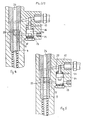
- Fig. 1 est une vue en coupe frontale d'un injecteur de moteur Diesel équipé selon l'invention.Fig. 1 is a front sectional view of a diesel engine injector equipped according to the invention.
- Fig. 2 est une coupe suivant II/II (Fig.1).Fig. 2 is a section along II / II (Fig. 1).
- Fig. 3 est une coupe en plan suivant III/III (Fig. 2).Fig. 3 is a sectional view along line III / III (Fig. 2).
- Fig. 4 est une coupe analogue à la figure 2, montrant la position des organes pendant une injection normale.Fig. 4 is a section similar to FIG. 2, showing the position of the organs during a normal injection.
- Fig. 5 est une vue analogue aux figures 2 et 4, montrant la position des organes en cas d'incident, l'aiguille d'in- jecteur étant grippée et en position ouverte.Fig. 5 is a view similar to Figures 2 and 4, showing the position of the organs in the event of incident, the in- needle jth ctor and being jammed in the open position.
On a représenté sur le dessin, l'ensemble d'un injecteur et d'un porte-injecteur pour moteur Diesel, équipé d'un dispositif selon l'invention.There is shown in the drawing, the assembly of an injector and an injector holder for a diesel engine, equipped with a device according to the invention.
A l'intérieur du porte-injecteur 1 se trouve à la manière connue un injecteur 2 dont l'extrémité comporte d'injection 3.Inside the
Derrière ces orifices 3 se trouve un siège d'étanchéité non représenté sur lequel peut venir porter à la manière connue l'extrémité d'une aiguille d'injecteur 4. La queue 5 de l'aiguille d'injecteur 4 reçoit un embout 6 derrière lequel prend appui un ressort de rappel taré 7. L'embout 6 fait partie d'un poussoir 8 qui, selon l'invention, présente une partie cylindrique arrière 9 jouant le rôle d'un distributeur hydraulique.Behind these orifices 3 is a sealing seat, not shown, on which the end of an
Pendant le fonctionnement du moteur, l'aiguille 4 se soulève à chaque injection et il en résulte pour le tiroir 9 un mouvement alternatif de coulissement dans un corps de distributeur fixe 10. Le jeu entre le tiroir 9 et le corps 10 correspond à des tolérances d'usinage courantes sur les systèmes d'injection, pour assurer une étanchéité satisfaisante au liquide combustible lorsque celui-ci est à la pression habituelle,During operation of the engine, the
Le tiroir distributeur 9 comporte une gorge llqui est susceptible-de se déplacer devant un orifice fixe 12 qui possède une section de passage de valeur S. Cet orifice 12 est pratiqué dans le corps 10 et il communique avec une chambre cylindrique 13 dans laquelle peut coulisser de façon étanche un piston différentiel comportant une grande section 14 et une petite section 15. Le corps à grosse section 14 de ce piston 14, 15 coulisse dans la chambre cylindrique 13 entre un ressort de rappel 16 et une poussée antagoniste provenant du combustible admis par l'orifice 12.The
Lorsque la pression dans la chambre 13 est faible ou nulle, le piston 14 occupe la position de repos illustrée sur la figure 2, c'est-à-dire qu'une butée arrière 17 dont il est pourvu reste en appui contre le fond de la chambre 13, matérialisé par un bouchon vissé 18.When the pressure in the
A l'avant du piston 14, 15, la petite section 15 est celle d'une tige cylindrique coulissant de façon étanche dans un allésage cylindrique fixe 19. Ce dernier est disposé en travers d'un canal d'alimentation 20 que la petite section 15 vient obturer complètement lorsque le piston différentiel 15, 16 occupe la position soulevée illustrée sur la figure 5.At the front of the
Un ajutage 21 à section calibrée s relie par ailleurs la chambre 13 à un circuit de décharge non représenté qui renvoie le combustible au réservoir.A
Par ailleurs, la chambre située autour du ressort de rappel 16 est reliée elle aussi par un orifice de fuite 22, au circuit de décharge renvoyant le combustible au réservoir.Furthermore, the chamber located around the
Le canal 20 reçoit à la manière connue le débit principal de combustible provenant de la pompe à haute pression du circuit d'injection.The
Ce canal 20 communique à la manière habituelle par des perçages tels que 23 prévus dans le corps du porte-injecteur 1, avec la chambre d'injection non représentée qui se trouve derrière le siège d'étanchéité, à l'extrémité de l' aiguille 4, pour injecter le combustible dans le moteur par les orifices 3, dès que l'aiguille 4 se soulève.This
Par ailleurs, la partie arrière du porte-injecteur 1 comporte un perçage axial 24 recevant d'un distributeur hydraulique, du combustible envoyé sous une pression modulée à la façon connue. On rappellera que,sur ces systèmes connus :
- - lorsque le combustible situé en 24 est à haute pression, son action sur la section du
distributeur 9 l'emporte et maintient fermée l'aiguille 4, à l'encontre de la pression antagoniste dans lescanalisations 20 et 23 ; - - au contraire, lorsque la pression en 24 chute, c'est la pression en 20 et 23 qui devient prépondérante et soulève l'aiguille 4, provoquant ainsi le début d'injection par les
orifices 23.
- - When the fuel located at 24 is at high pressure, its action on the section of the
distributor 9 prevails and keeps theneedle 4 closed, against the opposing pressure in thelines - - on the contrary, when the pressure at 24 drops, it is the pressure at 20 and 23 which becomes preponderant and lifts the
needle 4, thus causing the start of injection through theorifices 23.
Selon l'invention, on prévoit sur l'arrière du tiroir distributeur 9, un perçage 25 qui met en communication la gorge 11 avec le perçage axial 24.According to the invention, a
L'ensemble des deux orifices calibrés 12 (section S) et 21 (section s) constitue un moyen temporisateur pour le fonctionnement duquel on confère à S une valeur supérieure à celle. de s.The set of two calibrated orifices 12 (section S) and 21 (section s) constitutes a timer means for the operation of which S is given a value greater than that. from s.
Le fonctionnement est le suivant
- en position de repos, c'est-à-dire entre deux injections, le dispositif occupe la position illustrée sur les figures 1 et 2. La
gorge 11 dudistributeur 9 se trouve décalée par rapport à l'orifice 12. Par conséquent, la pression régnant en 24 ne parvient pas jusqu'à lachambre 13 du piston différentiel 14,15. Cettechambre 13 est maintenue à la pression de décharge par l'ajutage 21. Le piston différentiel 14,15 est soumis à la seule poussée de sonressort 16, et sabutée 17 reste en appui contre le fond dubouchon 18. Dans ces conditions, le canal d'alimentation 20 n'est pas obturé et le combustible sous haute pression (par exemple aux environs de 1000 bars) alimente en permanence lacanalisation 23. Celle-ci reste prête à provoquer le soulèvement de l'aiguille 4 et à déclencher un début d'injection dès qu'une baisse de pression sera provoqué volontairement dans leperçage 24.
- in the rest position, that is to say between two injections, the device occupies the position illustrated in FIGS. 1 and 2. The
groove 11 of thedistributor 9 is offset relative to theorifice 12. Consequently, the pressure prevailing at 24 does not reach thechamber 13 of thedifferential piston chamber 13 is maintained at the discharge pressure by thenozzle 21. Thedifferential piston spring 16, and itsstop 17 remains in abutment against the bottom of theplug 18. Under these conditions , thesupply channel 20 is not blocked and the fuel under high pressure (for example around 1000 bars) permanently feeds thepipe 23. The latter remains ready to cause the lift ment ofneedle 4 and triggering the start of injection as soon as a drop in pressure is voluntarily caused inbore 24.
Pendant une injection normale, c'est-à-dire à la suite d'une chute de la pression du combustible dans le perçage axial 24, l'aiguille 4 se soulève et l'ensemble occupe la position illustrée sur la figure 4. La gorge 11 du tiroir distributeur 9 vient en coincidence avec l'orifice calibré 12. Ce dernier est désormais alimenté en combustible sous haute pression à partir du perçage axial 24, dans l'inter-. médiaire du perçage 25.During a normal injection, that is to say following a drop in the fuel pressure in the
La pression monte dans la chambre 13, étant donné que la section de passage S de l'orifice d'alimentation 12 est supérieure à la surface s de l'ajutage de fuite 21. La loi de cette montée en pression dans la chambre 13 en fonction du temps peut être défini à volonté par le choix initial de la valeur relative des sections S et s. Les valeurs respectives de S et de s sont choisies de façon que la montée en pression dans la chambre 13 du piston différentiel 14,15 soit suffisamment lente pour ne pas devenir prépondérante par rapport à la poussée de tarage du ressort 16, pendant une durée au moins égale à la plus longue durée possible d'une injection selon les diverses conditions possibles de fonctionnement du moteur.The pressure rises in the
Dans ces conditions, on comprend que le piston différentiel 14,15 reste constamment immobile à la position illustrée sur la figure 4, tant que l'aiguille 4 de l'injecteur fonctionne de façon normale. En effet, à chaque début d'injection, l'aiguille 4 se soulève, la gorge 11 vient en coïncidence avec l'orifice 12, et la pression commence à monter dans la chambre 13. Cependant, avant que cette pression n'ait suffisamment monté pour écraser le ressort 16 et déplacer le piston obturateur 14,15, l'injection s'est terminée, et l'aiguille 4 est retombée sur son siège, la gorge 11 revenant à la position de la figure 2, ce qui coupe l'alimentation de l'orifice 12. La chambre 13 cessant désormais d'être alimentée alors que l'ajutage 21 la relie à la décharge, sa pression retombe et le piston différentiel 14, 15, reste immobile.Under these conditions, it is understood that the
C'est seulement en cas d'incident (figure 5) que le sustè- me fonctionne. En effet, l'aiguille 4 s'étant soulevée lors d'une injection (ce qui amène la gorge 11 en coincidence avec l'orifice 12), on suppose que l'aiguille 4 reste grippée ouverte dans son injecteur 2. Dans ces conditions, le ressort 7 est impuissant à la faire retomber sur son siège et le distributeur 9 reste immobilisé à la position de la figure 5. Dans ces conditions, comme expliqué précédemment, la pression monte dans la chambre 13 mais, la communication 11-12 restant indéfiniment établie, cette pression atteint une valeur dépassant le seuil défini par le tarage du ressort 16. Dès qu'elle dépasse ce seuil, sa poussée devient prépondérante et le piston différentiel 14,15 écrase le ressort 16 jusqu'à la position illustrée sur la figure 5. Dans ce cas, la tige à petite section 15 du'piston différentiel vient obturer complètement la canalisation 20 assurant l'alimentation de l'injecteur 2. Par conséquent, tant que l'aiguille 4 reste ouverte, l'alimentation en combustible cesse par les canalisations 20, 23. On supprime ainsi l'incident qui, sur un moteur classique, aurait conduit l'injecteur 2 à débiter en permanence du combustible dans le moteur.It is only in the event of an incident (Figure 5) that the sustè- works for me. Indeed, the
Claims (9)
Priority Applications (1)
| Application Number | Priority Date | Filing Date | Title |
|---|---|---|---|
| AT82420032T ATE12674T1 (en) | 1981-03-26 | 1982-03-12 | INJECTION SYSTEMS WITH PILOT-CONTROLLED INJECTION VALVE FOR COMBUSTION ENGINES. |
Applications Claiming Priority (2)
| Application Number | Priority Date | Filing Date | Title |
|---|---|---|---|
| FR8106572A FR2502701A1 (en) | 1981-03-26 | 1981-03-26 | INJECTOR INJECTION SYSTEM FOR AN INTERNAL COMBUSTION ENGINE |
| FR8106572 | 1981-03-26 |
Publications (2)
| Publication Number | Publication Date |
|---|---|
| EP0061979A1 true EP0061979A1 (en) | 1982-10-06 |
| EP0061979B1 EP0061979B1 (en) | 1985-04-10 |
Family
ID=9256894
Family Applications (1)
| Application Number | Title | Priority Date | Filing Date |
|---|---|---|---|
| EP82420032A Expired EP0061979B1 (en) | 1981-03-26 | 1982-03-12 | Injection system with pilot-operated injector for an internal combustion engine |
Country Status (6)
| Country | Link |
|---|---|
| US (1) | US4467757A (en) |
| EP (1) | EP0061979B1 (en) |
| JP (1) | JPS58117356A (en) |
| AT (1) | ATE12674T1 (en) |
| DE (1) | DE3262934D1 (en) |
| FR (1) | FR2502701A1 (en) |
Cited By (5)
| Publication number | Priority date | Publication date | Assignee | Title |
|---|---|---|---|---|
| FR2558533A1 (en) * | 1984-01-23 | 1985-07-26 | Renault | SAFETY DEVICE FOR INJECTION VALVE OF INTERNAL COMBUSTION ENGINE |
| EP0385399A2 (en) * | 1989-03-03 | 1990-09-05 | ELASIS SISTEMA RICERCA FIAT NEL MEZZOGIORNO Società Consortile per Azioni | Perfected Diesel engine electromagnetic fuel injector |
| FR2665930A1 (en) * | 1990-08-17 | 1992-02-21 | Daimler Benz Ag | PUMP AND INJECTOR INJECTION SYSTEM AND SOLENOID VALVE CONTROL FOR INTERNAL COMBUSTION ENGINE WITH AIR COMPRESSION. |
| FR2756013A1 (en) * | 1996-11-15 | 1998-05-22 | Daimler Benz Ag | FUEL INJECTION INSTALLATION FOR INTERNAL COMBUSTION ENGINE |
| FR2759740A1 (en) * | 1997-02-19 | 1998-08-21 | Daimler Benz Ag | ACCUMULATOR INJECTION DEVICE FOR MULTICYLINDRICAL INTERNAL COMBUSTION ENGINES |
Families Citing this family (9)
| Publication number | Priority date | Publication date | Assignee | Title |
|---|---|---|---|---|
| US4539959A (en) * | 1984-02-27 | 1985-09-10 | General Motors Corporation | Fuel injection system with fuel flow limiting valve assembly |
| DE4002206C2 (en) * | 1990-01-26 | 2000-06-15 | Bosch Gmbh Robert | Catalyst protection process |
| WO1992012341A1 (en) * | 1991-01-14 | 1992-07-23 | Nippondenso Co., Ltd. | Pressure accumulation type fuel jetting device |
| US5537972A (en) * | 1994-07-28 | 1996-07-23 | Servojet Electronics Systems | Fuel injection system having a pressure intensifier incorporating an overtravel safety feature |
| DE19717419C1 (en) * | 1997-04-25 | 1998-07-30 | Daimler Benz Ag | Injector valve for internal combustion engine of vehicle |
| DE69916363T2 (en) * | 1998-05-29 | 2005-03-24 | Toyota Jidosha K.K., Toyota | Fuel supply for internal combustion engine |
| FR2853358B1 (en) * | 2003-04-04 | 2005-05-06 | Peugeot Citroen Automobiles Sa | INTERNAL COMBUSTION ENGINE WITH GASOLINE AND SELF IGNITION |
| FR2853354B1 (en) * | 2003-04-04 | 2006-06-09 | Peugeot Citroen Automobiles Sa | INTERNAL COMBUSTION ENGINE WITH DIRECT FUEL INJECTION AND IGNITION CONTROL |
| FR2853356B1 (en) * | 2003-04-04 | 2006-06-30 | Peugeot Citroen Automobiles Sa | INTERNAL COMBUSTION ENGINE WITH GASOLINE AND IGNITION CONTROL COMPRISING A VERY HIGH PRESSURE INJECTION SYSTEM |
Citations (5)
| Publication number | Priority date | Publication date | Assignee | Title |
|---|---|---|---|---|
| FR1555369A (en) * | 1967-03-22 | 1969-01-24 | ||
| US3443760A (en) * | 1967-04-26 | 1969-05-13 | Parker Hannifin Corp | Fail-safe fuel injection nozzle |
| FR2125946A5 (en) * | 1971-02-19 | 1972-09-29 | Cav Ltd | |
| DE2754615A1 (en) * | 1977-12-08 | 1979-06-13 | Bosch Gmbh Robert | IC engine injector shut=off device - has solenoid valve metering fuel stored in chamber per injection |
| GB2051229A (en) * | 1979-06-01 | 1981-01-14 | Maschf Augsburg Nuernberg Ag | Fuel Injection Device for an Internal Combustion Engine |
Family Cites Families (9)
| Publication number | Priority date | Publication date | Assignee | Title |
|---|---|---|---|---|
| US3104817A (en) * | 1963-09-24 | Fuel injector with pilot injection | ||
| US2067997A (en) * | 1934-05-07 | 1937-01-19 | White Eli | Fuel injector for internal combustion engines |
| US2053311A (en) * | 1934-06-13 | 1936-09-08 | Amery George | Fuel and like pump for internal combustion engines |
| US2912168A (en) * | 1956-03-03 | 1959-11-10 | Orange G M B H L | Fuel injection unit |
| US2934138A (en) * | 1958-01-06 | 1960-04-26 | Lucas Industries Ltd | Means for controlling the supply of liquid fuel to a gas turbine |
| US3016838A (en) * | 1959-02-09 | 1962-01-16 | Bessiere Pierre Etienne | Reciprocating action pumps, in particular fuel injection pumps |
| US3645245A (en) * | 1970-09-04 | 1972-02-29 | Caterpillar Tractor Co | Speed limiter for hydraulic governor |
| US3951117A (en) * | 1974-05-30 | 1976-04-20 | Cummins Engine Company, Inc. | Fuel supply system for an internal combustion engine |
| US4369750A (en) * | 1979-12-19 | 1983-01-25 | Cummins Engine Company, Inc. | Fuel injector for internal combustion engine |
-
1981
- 1981-03-26 FR FR8106572A patent/FR2502701A1/en not_active Withdrawn
-
1982
- 1982-03-12 EP EP82420032A patent/EP0061979B1/en not_active Expired
- 1982-03-12 AT AT82420032T patent/ATE12674T1/en not_active IP Right Cessation
- 1982-03-12 DE DE8282420032T patent/DE3262934D1/en not_active Expired
- 1982-03-23 US US06/361,014 patent/US4467757A/en not_active Expired - Fee Related
- 1982-03-26 JP JP57049929A patent/JPS58117356A/en active Pending
Patent Citations (5)
| Publication number | Priority date | Publication date | Assignee | Title |
|---|---|---|---|---|
| FR1555369A (en) * | 1967-03-22 | 1969-01-24 | ||
| US3443760A (en) * | 1967-04-26 | 1969-05-13 | Parker Hannifin Corp | Fail-safe fuel injection nozzle |
| FR2125946A5 (en) * | 1971-02-19 | 1972-09-29 | Cav Ltd | |
| DE2754615A1 (en) * | 1977-12-08 | 1979-06-13 | Bosch Gmbh Robert | IC engine injector shut=off device - has solenoid valve metering fuel stored in chamber per injection |
| GB2051229A (en) * | 1979-06-01 | 1981-01-14 | Maschf Augsburg Nuernberg Ag | Fuel Injection Device for an Internal Combustion Engine |
Cited By (9)
| Publication number | Priority date | Publication date | Assignee | Title |
|---|---|---|---|---|
| FR2558533A1 (en) * | 1984-01-23 | 1985-07-26 | Renault | SAFETY DEVICE FOR INJECTION VALVE OF INTERNAL COMBUSTION ENGINE |
| EP0150138A2 (en) * | 1984-01-23 | 1985-07-31 | Regie Nationale Des Usines Renault | Safety device for constant-pressure fuel-injection valve of an internal combustion engine |
| EP0150138A3 (en) * | 1984-01-23 | 1985-09-11 | Regie Nationale Des Usines Renault | Safety device for constant-pressure fuel-injection valve of an internal combustion engine |
| US4589393A (en) * | 1984-01-23 | 1986-05-20 | Regie Nationale Des Usines Renault | Safety device for constant-pressure injection valve of internal combustion engine |
| EP0385399A2 (en) * | 1989-03-03 | 1990-09-05 | ELASIS SISTEMA RICERCA FIAT NEL MEZZOGIORNO Società Consortile per Azioni | Perfected Diesel engine electromagnetic fuel injector |
| EP0385399A3 (en) * | 1989-03-03 | 1991-06-19 | ELASIS SISTEMA RICERCA FIAT NEL MEZZOGIORNO Società Consortile per Azioni | Perfected diesel engine electromagnetic fuel injector |
| FR2665930A1 (en) * | 1990-08-17 | 1992-02-21 | Daimler Benz Ag | PUMP AND INJECTOR INJECTION SYSTEM AND SOLENOID VALVE CONTROL FOR INTERNAL COMBUSTION ENGINE WITH AIR COMPRESSION. |
| FR2756013A1 (en) * | 1996-11-15 | 1998-05-22 | Daimler Benz Ag | FUEL INJECTION INSTALLATION FOR INTERNAL COMBUSTION ENGINE |
| FR2759740A1 (en) * | 1997-02-19 | 1998-08-21 | Daimler Benz Ag | ACCUMULATOR INJECTION DEVICE FOR MULTICYLINDRICAL INTERNAL COMBUSTION ENGINES |
Also Published As
| Publication number | Publication date |
|---|---|
| US4467757A (en) | 1984-08-28 |
| DE3262934D1 (en) | 1985-05-15 |
| ATE12674T1 (en) | 1985-04-15 |
| JPS58117356A (en) | 1983-07-12 |
| EP0061979B1 (en) | 1985-04-10 |
| FR2502701A1 (en) | 1982-10-01 |
Similar Documents
| Publication | Publication Date | Title |
|---|---|---|
| EP0061979B1 (en) | Injection system with pilot-operated injector for an internal combustion engine | |
| EP1188974B1 (en) | Self-cleaning dosing device | |
| EP1059952B1 (en) | Dispensing device for fluid product activated by inhaling | |
| CH644187A5 (en) | FUEL INJECTION DEVICE, PARTICULARLY FOR DIESEL ENGINES. | |
| EP0995031B1 (en) | Device for injecting fuel into a diesel engine | |
| CA2345735C (en) | Disposable injection device designed to be pre-filled | |
| EP2964933B1 (en) | Compact dosing device for an injector with two fuel circuits for an aircraft turbomachine | |
| FR2474101A1 (en) | REGENERATION INJECTION DEVICE EQUIPPED WITH VALVES FOR ENGINE-ROCKET | |
| EP1312864B1 (en) | Dosing device for turbomachine fuel injector | |
| FR2696613A1 (en) | Arc plasma torch and method of implementation. | |
| EP3708899B1 (en) | Valve, container for pressurised fluid and filling and extraction methods | |
| EP0493155B1 (en) | Valve and method for bleeding of hydraulic circuit | |
| EP1948532B1 (en) | Pump triggering and dispensing head | |
| CA2126803C (en) | Electrical connection system | |
| EP1497039B1 (en) | Distribution pump for a liquid product | |
| FR2540482A1 (en) | DISTRIBUTION GUN FOR A FILLED PIPE LIQUID DISPENSER | |
| WO2007045803A1 (en) | Valve with cushioned opening system | |
| FR2724958A1 (en) | Water distributor for WC | |
| EP2283223A1 (en) | Pressurized gas receiving device, dispenser-receiving device assembly, and corresponding supply system | |
| FR2482670A1 (en) | FUEL INJECTOR | |
| EP1116909B1 (en) | Float controlled valve | |
| EP3511476B1 (en) | Flushing valve for toilet bowls comprising a double actuation mechanism for releasing a large or a small volume of flushwater | |
| CH463000A (en) | Injector for pressurized spraying of liquid fuels | |
| WO1994018040A1 (en) | Pressure shift valve and electrical by-pass | |
| FR2798704A1 (en) | LEAKAGE CONNECTION DEVICE FOR MOUNTING A LEAKAGE DUCT ON A FUEL INJECTOR |
Legal Events
| Date | Code | Title | Description |
|---|---|---|---|
| PUAI | Public reference made under article 153(3) epc to a published international application that has entered the european phase |
Free format text: ORIGINAL CODE: 0009012 |
|
| AK | Designated contracting states |
Designated state(s): AT BE CH DE GB IT LU NL SE |
|
| 17P | Request for examination filed |
Effective date: 19821008 |
|
| ITF | It: translation for a ep patent filed |
Owner name: MARCHI & MITTLER S.R.L. |
|
| GRAA | (expected) grant |
Free format text: ORIGINAL CODE: 0009210 |
|
| AK | Designated contracting states |
Designated state(s): AT BE CH DE GB IT LI LU NL SE |
|
| REF | Corresponds to: |
Ref document number: 12674 Country of ref document: AT Date of ref document: 19850415 Kind code of ref document: T |
|
| REF | Corresponds to: |
Ref document number: 3262934 Country of ref document: DE Date of ref document: 19850515 |
|
| PLBE | No opposition filed within time limit |
Free format text: ORIGINAL CODE: 0009261 |
|
| STAA | Information on the status of an ep patent application or granted ep patent |
Free format text: STATUS: NO OPPOSITION FILED WITHIN TIME LIMIT |
|
| PG25 | Lapsed in a contracting state [announced via postgrant information from national office to epo] |
Ref country code: AT Effective date: 19860312 |
|
| PG25 | Lapsed in a contracting state [announced via postgrant information from national office to epo] |
Ref country code: SE Effective date: 19860313 |
|
| PG25 | Lapsed in a contracting state [announced via postgrant information from national office to epo] |
Ref country code: LU Free format text: LAPSE BECAUSE OF NON-PAYMENT OF DUE FEES Effective date: 19860331 Ref country code: LI Effective date: 19860331 Ref country code: CH Effective date: 19860331 Ref country code: BE Effective date: 19860331 |
|
| 26N | No opposition filed | ||
| BERE | Be: lapsed |
Owner name: RENAULT VEHICULES INDUSTRIELS Effective date: 19860331 |
|
| PG25 | Lapsed in a contracting state [announced via postgrant information from national office to epo] |
Ref country code: NL Effective date: 19861001 |
|
| GBPC | Gb: european patent ceased through non-payment of renewal fee | ||
| REG | Reference to a national code |
Ref country code: CH Ref legal event code: PL |
|
| PG25 | Lapsed in a contracting state [announced via postgrant information from national office to epo] |
Ref country code: DE Effective date: 19861202 |
|
| NLV4 | Nl: lapsed or anulled due to non-payment of the annual fee | ||
| PG25 | Lapsed in a contracting state [announced via postgrant information from national office to epo] |
Ref country code: GB Effective date: 19881121 |
|
| EUG | Se: european patent has lapsed |
Ref document number: 82420032.3 Effective date: 19870224 |