EP0061922B1 - Method, and system, for spraying - Google Patents
Method, and system, for spraying Download PDFInfo
- Publication number
- EP0061922B1 EP0061922B1 EP82301640A EP82301640A EP0061922B1 EP 0061922 B1 EP0061922 B1 EP 0061922B1 EP 82301640 A EP82301640 A EP 82301640A EP 82301640 A EP82301640 A EP 82301640A EP 0061922 B1 EP0061922 B1 EP 0061922B1
- Authority
- EP
- European Patent Office
- Prior art keywords
- nozzle
- voltage
- spray unit
- medium
- detected voltage
- Prior art date
- Legal status (The legal status is an assumption and is not a legal conclusion. Google has not performed a legal analysis and makes no representation as to the accuracy of the status listed.)
- Expired
Links
Images


Classifications
-
- G—PHYSICS
- G01—MEASURING; TESTING
- G01F—MEASURING VOLUME, VOLUME FLOW, MASS FLOW OR LIQUID LEVEL; METERING BY VOLUME
- G01F1/00—Measuring the volume flow or mass flow of fluid or fluent solid material wherein the fluid passes through a meter in a continuous flow
- G01F1/56—Measuring the volume flow or mass flow of fluid or fluent solid material wherein the fluid passes through a meter in a continuous flow by using electric or magnetic effects
- G01F1/64—Measuring the volume flow or mass flow of fluid or fluent solid material wherein the fluid passes through a meter in a continuous flow by using electric or magnetic effects by measuring electrical currents passing through the fluid flow; measuring electrical potential generated by the fluid flow, e.g. by electrochemical, contact or friction effects
-
- B—PERFORMING OPERATIONS; TRANSPORTING
- B05—SPRAYING OR ATOMISING IN GENERAL; APPLYING FLUENT MATERIALS TO SURFACES, IN GENERAL
- B05B—SPRAYING APPARATUS; ATOMISING APPARATUS; NOZZLES
- B05B12/00—Arrangements for controlling delivery; Arrangements for controlling the spray area
- B05B12/004—Arrangements for controlling delivery; Arrangements for controlling the spray area comprising sensors for monitoring the delivery, e.g. by displaying the sensed value or generating an alarm
- B05B12/006—Pressure or flow rate sensors
-
- B—PERFORMING OPERATIONS; TRANSPORTING
- B05—SPRAYING OR ATOMISING IN GENERAL; APPLYING FLUENT MATERIALS TO SURFACES, IN GENERAL
- B05B—SPRAYING APPARATUS; ATOMISING APPARATUS; NOZZLES
- B05B12/00—Arrangements for controlling delivery; Arrangements for controlling the spray area
- B05B12/08—Arrangements for controlling delivery; Arrangements for controlling the spray area responsive to condition of liquid or other fluent material to be discharged, of ambient medium or of target ; responsive to condition of spray devices or of supply means, e.g. pipes, pumps or their drive means
- B05B12/085—Arrangements for controlling delivery; Arrangements for controlling the spray area responsive to condition of liquid or other fluent material to be discharged, of ambient medium or of target ; responsive to condition of spray devices or of supply means, e.g. pipes, pumps or their drive means responsive to flow or pressure of liquid or other fluent material to be discharged
-
- B—PERFORMING OPERATIONS; TRANSPORTING
- B05—SPRAYING OR ATOMISING IN GENERAL; APPLYING FLUENT MATERIALS TO SURFACES, IN GENERAL
- B05B—SPRAYING APPARATUS; ATOMISING APPARATUS; NOZZLES
- B05B15/00—Details of spraying plant or spraying apparatus not otherwise provided for; Accessories
- B05B15/50—Arrangements for cleaning; Arrangements for preventing deposits, drying-out or blockage; Arrangements for detecting improper discharge caused by the presence of foreign matter
Definitions
- This invention relates to a spraying system and to a method of operating a spray unit.
- medium is used in this specification to cover not only homogeneous liquids but also heretogeneous liquids in which particulate or fibrous components are borne by a carrier liquid.
- a typical spraying system for depositing medium such as paint or other protective material onto prefabricated units comprises a bulk storage from which a pump withdraws and pressurises medium for feeding along pipework to a spray gun for use in processes known as "airless” or “air assisted” spraying.
- a pump withdraws and pressurises medium for feeding along pipework to a spray gun for use in processes known as "airless” or “air assisted” spraying.
- an accumulator would be fitted to smooth the flow of medium.
- the gun incorporates a jet, nozzle or tip from which atomised medium issues in a spray pattern.
- the spray pattern is dependent on a number of factors including jet shape and size, the pressure drop across the jet, the viscosity of the medium to be sprayed and (for air assisted spraying) the air supply characteristics.
- the spray pattern produced changes if any of these factors change and it is therefore often difficultto operate the spraying system in a stable manner.
- FR-A-1 216721 discloses a system for injection of fuel into a combustion engine and makes use of the phenomenon that electrostatic charges are induced when a fluid flows through a conduit to measure the flow rate of the fuel.
- a spraying system comprising a spray unit having a nozzle which is arranged to be coupled by a feed line to a pump supplying pressurised medium, the nozzle being formed of electrically conducting material but electrically isolated from the remainder of the spray unit; a voltage monitor for detecting the voltage on the nozzle; a setting device for establishing one or more predetermined voltages indicative of a desired or optimum spray pattern; and a comparator for comparing predetermined voltages with the detected voltage.
- a method of operating a spray unit having a nozzle which is formed of electrically conducting material but is electrically isolated from the remainder of the spray unit comprising the steps of: detecting the voltage on the nozzle as a medium is sprayed therefrom and comparing the detected voltage with one or more predetermined voltages indicative of a desired or optimum spray pattern.
- the present invention arises from considering the ionising effect occurring in medium when it is forced under pressure through a jet or nozzle. In being forced through the jet electric charges are carried away in the spray of liquid and in material entrained with it and a charge of opposite polarity is retained on the conducting jet body. It has been found that the resulting instantaneous potential relative to a nominal earth provides a measure of the stability and other operating characteristics of the resulting spray pattern.
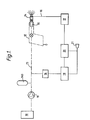
- Figures 1 and 2 are block diagrams of spray systems for depositing a protective medium on a vehicle body during manufacture thereof; and Figure 3 shows variations in voltage, relative to time, of a spray nozzle referred to in connection with Figures 1 and 2.
- Figures 1 and 2 similar reference numerals are used to refer to components having a similar function.
- the flow of coating medium through the system in both figures is shown by a broken line. Electrical connections are shown by continuous lines.
- Coating medium from a bulk supply 10 is fed by a reciprocating pump 11 to the body 12 of a spray gun by way of a supply line 13.
- Accumulator 140 is coupled to the supply line 13 and functions to absorb pressure pulses occurring in medium in line 13.
- the body 12 has secured to it a spray nozzle 14 (otherwise known as a jet or tip) which is of a material of low electrical resistance.
- the nozzle 14 is secured to the body 12 by way of a collar 15 of material which is an electrical insulator.
- the body 12 of the gun is earthed.
- Nozzle 14 is connected by a line 16 to a voltage monitoring unit 17. Liquid pressure in line 13 is detected by means of a pressure transducer 18 whose output is fed to adjustable limit setting units 19, 20.
- Unit 19 provides as output a signal or signals representing the limiting continuous operation pressures which are acceptable during operation of the system.
- Unit 20 provides a signal representing predetermined limits of operating pressure for transient pressure pulses for the system and voltage detected on the jet body. In the event that either or both units 19, 20 detects an out-of-limit condition, an alarm 21 is operated. Under normal operating conditions, the output of transducer 18 is also fed to a monitor (not shown) to display a visual trace of the operation of the system for evaluation by an operator.
- FIG. 3 shows a typical visual display record of voltage (V) in the form of a voltage analogue against time (T).
- Trace 101 is of a voltage analogue corresponding to supply line pressure as sensed by transducer 18.
- the distinctively humped appearance arises from the pressurising of the medium in the supply line 13 by the pump 11 which is of double acting reciprocating type.
- the fine pressure limits shown as traces 102, 103 are generated by fine limit setting unit 19.
- the gross predetermined limits of traces 104, 105 are generated by gross limit setting unit 20.
- the trace 106 represent the voltage arising from the electrical charge generated on the body 14 of the nozzle on ionisation of medium forced through the nozzle and forming a spray of medium for subsequent deposition on a vehicle body.
- FIG. 2 in addition to items whose function is similar to that already described in connection with Figure 1, incorporates certain additional components.
- the nozzle 14 has mounted with it on gun 12 a nozzle size adjuster 23 (which incorporates a mechanical clearing device).
- a feedback control unit 24 responds to an output from the monitor 17 and energises the adjustor 23 to act in a sense to restore the voltage on nozzle body 14 to the predetermined value. This can be achieved by either momentarily changing the size of the nozzle or by operating a mechanical device for clearing the orifice. In this situation the nozzle body 14, monitor 17, control unit 24 and adjustor 23 operate as a feedback loop controlling the operation of the jet in nozzle body 14.
- a pump control unit 25 is provided as an alternative to the adjustor 23 or as a further regulator for operation of the system.
- the feedback control 24 transmits a signal to pump control unit 25 if the monitor 17 output indicates a progressive change in the voltage on the nozzle body 14. This could arise, for example, in the use of a fresh supply of medium which differs in viscosity from the medium previously used. In this case the control 24 operates to cause the pump control unit 25 to appropriately vary the pump speed.
- Fig. 2 One advantage afforded by the embodiment illustrated in Fig. 2 arises from the self-regulatory control of the system. Once the system has been set up to provide an optimised spray pattern from the jet the system tends to restore the desired pattern regardless of changes such as partial blockages, changes in pressure drop, and changes in medium viscosity. The system described thus lends itself for use in robot spraying systems or in spraying environments where a human operator would be faced with health hazard.
- voltage traces corresponding to trace 106 in Figure 3 enable a range of information as to the system and the sprayed material to be obtained.
- the wear of the jet can be sensed so that jets nearing the end of their useful life can be replaced.
- the condition of the medium to be sprayed gives a distinctive pattern whose displacement indicates a change in a material characteristic such as density or homogeneity. Deterioration or unauthorised modification in pump performance can be identified at an early stage. Blockage in the supply line also produces a displacement in the trace pattern which allows rectification before efficient operation is impaired. It is also possible to check that the spray pattern is appropriate on setting up a new jet for a given function.
Landscapes
- Chemical & Material Sciences (AREA)
- Physics & Mathematics (AREA)
- Analytical Chemistry (AREA)
- Fluid Mechanics (AREA)
- General Physics & Mathematics (AREA)
- Electrochemistry (AREA)
- Chemical Kinetics & Catalysis (AREA)
- Application Of Or Painting With Fluid Materials (AREA)
- Electrostatic Spraying Apparatus (AREA)
- Spray Control Apparatus (AREA)
- Nozzles (AREA)
- Details Or Accessories Of Spraying Plant Or Apparatus (AREA)
- Coating By Spraying Or Casting (AREA)
Abstract
Description
- This invention relates to a spraying system and to a method of operating a spray unit.
- The term "medium" is used in this specification to cover not only homogeneous liquids but also heretogeneous liquids in which particulate or fibrous components are borne by a carrier liquid.
- A typical spraying system for depositing medium such as paint or other protective material onto prefabricated units comprises a bulk storage from which a pump withdraws and pressurises medium for feeding along pipework to a spray gun for use in processes known as "airless" or "air assisted" spraying. In the case where the pump produces pulses or surges an accumulator would be fitted to smooth the flow of medium. The gun incorporates a jet, nozzle or tip from which atomised medium issues in a spray pattern. The spray pattern is dependent on a number of factors including jet shape and size, the pressure drop across the jet, the viscosity of the medium to be sprayed and (for air assisted spraying) the air supply characteristics. The spray pattern produced changes if any of these factors change and it is therefore often difficultto operate the spraying system in a stable manner.
- FR-A-1 216721 discloses a system for injection of fuel into a combustion engine and makes use of the phenomenon that electrostatic charges are induced when a fluid flows through a conduit to measure the flow rate of the fuel.
- According to a first aspect of this invention there is provided a spraying system comprising a spray unit having a nozzle which is arranged to be coupled by a feed line to a pump supplying pressurised medium, the nozzle being formed of electrically conducting material but electrically isolated from the remainder of the spray unit; a voltage monitor for detecting the voltage on the nozzle; a setting device for establishing one or more predetermined voltages indicative of a desired or optimum spray pattern; and a comparator for comparing predetermined voltages with the detected voltage.
- According to a second aspect of this invention there is provided a method of operating a spray unit having a nozzle which is formed of electrically conducting material but is electrically isolated from the remainder of the spray unit comprising the steps of: detecting the voltage on the nozzle as a medium is sprayed therefrom and comparing the detected voltage with one or more predetermined voltages indicative of a desired or optimum spray pattern.
- Preferred features of this invention will be apparent from the subsidiary claims of the specification.
- The present invention arises from considering the ionising effect occurring in medium when it is forced under pressure through a jet or nozzle. In being forced through the jet electric charges are carried away in the spray of liquid and in material entrained with it and a charge of opposite polarity is retained on the conducting jet body. It has been found that the resulting instantaneous potential relative to a nominal earth provides a measure of the stability and other operating characteristics of the resulting spray pattern.
- Two embodiments of the invention will now be described with reference to the accompanying drawings of which: Figures 1 and 2 are block diagrams of spray systems for depositing a protective medium on a vehicle body during manufacture thereof; and Figure 3 shows variations in voltage, relative to time, of a spray nozzle referred to in connection with Figures 1 and 2. In the descriptions associated with Figures 1 and 2 similar reference numerals are used to refer to components having a similar function. The flow of coating medium through the system in both figures is shown by a broken line. Electrical connections are shown by continuous lines.
- Coating medium from a
bulk supply 10 is fed by a reciprocatingpump 11 to thebody 12 of a spray gun by way of asupply line 13.Accumulator 140 is coupled to thesupply line 13 and functions to absorb pressure pulses occurring in medium inline 13. Thebody 12 has secured to it a spray nozzle 14 (otherwise known as a jet or tip) which is of a material of low electrical resistance. Thenozzle 14 is secured to thebody 12 by way of acollar 15 of material which is an electrical insulator. Thebody 12 of the gun is earthed.Nozzle 14 is connected by aline 16 to avoltage monitoring unit 17. Liquid pressure inline 13 is detected by means of apressure transducer 18 whose output is fed to adjustablelimit setting units Unit 19 provides as output a signal or signals representing the limiting continuous operation pressures which are acceptable during operation of the system.Unit 20 provides a signal representing predetermined limits of operating pressure for transient pressure pulses for the system and voltage detected on the jet body. In the event that either or bothunits alarm 21 is operated. Under normal operating conditions, the output oftransducer 18 is also fed to a monitor (not shown) to display a visual trace of the operation of the system for evaluation by an operator. - Figure 3 shows a typical visual display record of voltage (V) in the form of a voltage analogue against time (T).
Trace 101 is of a voltage analogue corresponding to supply line pressure as sensed bytransducer 18. The distinctively humped appearance arises from the pressurising of the medium in thesupply line 13 by thepump 11 which is of double acting reciprocating type. The fine pressure limits shown astraces limit setting unit 19. The gross predetermined limits oftraces limit setting unit 20. Thetrace 106 represent the voltage arising from the electrical charge generated on thebody 14 of the nozzle on ionisation of medium forced through the nozzle and forming a spray of medium for subsequent deposition on a vehicle body. - Figure 2, in addition to items whose function is similar to that already described in connection with Figure 1, incorporates certain additional components. The
nozzle 14 has mounted with it on gun 12 a nozzle size adjuster 23 (which incorporates a mechanical clearing device). When thevoltage monitor 17 detects a change in voltage on nozzle body 14 (for example due to partial blockage of the nozzle with a consequent drop < in throughput of sprayable medium) a feedback control unit 24 responds to an output from themonitor 17 and energises theadjustor 23 to act in a sense to restore the voltage onnozzle body 14 to the predetermined value. This can be achieved by either momentarily changing the size of the nozzle or by operating a mechanical device for clearing the orifice. In this situation thenozzle body 14,monitor 17, control unit 24 andadjustor 23 operate as a feedback loop controlling the operation of the jet innozzle body 14. - A
pump control unit 25 is provided as an alternative to theadjustor 23 or as a further regulator for operation of the system. The feedback control 24 transmits a signal to pumpcontrol unit 25 if themonitor 17 output indicates a progressive change in the voltage on thenozzle body 14. This could arise, for example, in the use of a fresh supply of medium which differs in viscosity from the medium previously used. In this case the control 24 operates to cause thepump control unit 25 to appropriately vary the pump speed. - One advantage afforded by the embodiment illustrated in Fig. 2 arises from the self-regulatory control of the system. Once the system has been set up to provide an optimised spray pattern from the jet the system tends to restore the desired pattern regardless of changes such as partial blockages, changes in pressure drop, and changes in medium viscosity. The system described thus lends itself for use in robot spraying systems or in spraying environments where a human operator would be faced with health hazard.
- Apart from the self-regulatory control analysis of the tip, voltage traces corresponding to trace 106 in Figure 3 enable a range of information as to the system and the sprayed material to be obtained. The wear of the jet can be sensed so that jets nearing the end of their useful life can be replaced. The condition of the medium to be sprayed gives a distinctive pattern whose displacement indicates a change in a material characteristic such as density or homogeneity. Deterioration or unauthorised modification in pump performance can be identified at an early stage. Blockage in the supply line also produces a displacement in the trace pattern which allows rectification before efficient operation is impaired. It is also possible to check that the spray pattern is appropriate on setting up a new jet for a given function.
Claims (10)
Priority Applications (1)
| Application Number | Priority Date | Filing Date | Title |
|---|---|---|---|
| AT82301640T ATE14997T1 (en) | 1981-03-27 | 1982-03-29 | METHOD AND DEVICE FOR SPRAYING. |
Applications Claiming Priority (2)
| Application Number | Priority Date | Filing Date | Title |
|---|---|---|---|
| GB8109652 | 1981-03-27 | ||
| GB8109652 | 1981-03-27 |
Publications (3)
| Publication Number | Publication Date |
|---|---|
| EP0061922A2 EP0061922A2 (en) | 1982-10-06 |
| EP0061922A3 EP0061922A3 (en) | 1983-02-09 |
| EP0061922B1 true EP0061922B1 (en) | 1985-08-21 |
Family
ID=10520698
Family Applications (1)
| Application Number | Title | Priority Date | Filing Date |
|---|---|---|---|
| EP82301640A Expired EP0061922B1 (en) | 1981-03-27 | 1982-03-29 | Method, and system, for spraying |
Country Status (5)
| Country | Link |
|---|---|
| US (1) | US4712736A (en) |
| EP (1) | EP0061922B1 (en) |
| JP (1) | JPS57201560A (en) |
| AT (1) | ATE14997T1 (en) |
| DE (1) | DE3265535D1 (en) |
Families Citing this family (15)
| Publication number | Priority date | Publication date | Assignee | Title |
|---|---|---|---|---|
| DE3423094A1 (en) * | 1984-06-22 | 1986-01-02 | J. Wagner Gmbh, 7990 Friedrichshafen | METHOD AND DEVICE FOR ADJUSTING A FLOW CONTROL VALVE OF A PAINT SPRAY GUN |
| SE448667B (en) * | 1985-06-26 | 1987-03-16 | Frigoscandia Contracting Ab | SET TO CONTROL THE FLOW OF A FOOD INTO A DEVICE FOR TRANSMISSION OF FOOD TO STANDARD CONDITION AND APPLIANCE FOR THE SET |
| JPH0610262Y2 (en) * | 1987-12-29 | 1994-03-16 | 四国化工機株式会社 | Hydrogen peroxide water spray device |
| EP0350605A3 (en) * | 1988-07-12 | 1990-09-19 | Wagner International Ag | Two components spray installation |
| US4955164A (en) * | 1989-06-15 | 1990-09-11 | Flow Research, Inc | Method and apparatus for drilling small diameter holes in fragile material with high velocity liquid jet |
| US5038893A (en) * | 1989-09-25 | 1991-08-13 | Orsco, Inc. | Lubrication monitoring system |
| US5208064A (en) * | 1991-11-04 | 1993-05-04 | Nordson Corporation | Method and apparatus for optically monitoring and controlling a moving fiber of material |
| US5312039A (en) * | 1992-06-22 | 1994-05-17 | Vlsi Technology, Inc. | Electro-optic monitor for fluid spray pattern |
| US5316217A (en) * | 1993-08-23 | 1994-05-31 | Fanuc Robotics North America, Inc. | Method and system for detecting blockage in a spray gun of a liquid spray system |
| DE19651611A1 (en) * | 1996-12-12 | 1998-06-18 | Bosch Gmbh Robert | Device for measuring a particle state quantity |
| SE508511C2 (en) * | 1997-02-17 | 1998-10-12 | Abb Flexible Automation As | Device and method for supplying liquid to a spray nozzle for automatic spray application |
| US7792611B2 (en) * | 2004-10-01 | 2010-09-07 | Ingo Werner Scheer | Spray pattern characterization and monitoring method and system |
| JP2006321041A (en) * | 2005-04-20 | 2006-11-30 | Yaskawa Electric Corp | Internal pressure explosion-proof system |
| JP6864680B2 (en) * | 2015-11-04 | 2021-04-28 | ノードソン コーポレーションNordson Corporation | Methods and systems for controlling the fluid pattern of dispense fluids |
| CN113953112A (en) * | 2021-10-22 | 2022-01-21 | 西安热工研究院有限公司 | Intelligent dust-settling spray control method and system powered by solar energy for construction site |
Family Cites Families (12)
| Publication number | Priority date | Publication date | Assignee | Title |
|---|---|---|---|---|
| US2315805A (en) * | 1940-05-15 | 1943-04-06 | Frank V Mayo | Fluid meter |
| US2491445A (en) * | 1947-02-24 | 1949-12-13 | Shell Dev | Flowmeter |
| DE936671C (en) * | 1951-08-12 | 1955-12-15 | Siemens Ag | Device on a nozzle for electrostatic surface treatment |
| FR1216721A (en) * | 1959-02-13 | 1960-04-27 | Wissenschaftlich Tech Buero Fu | Device for the measurement of a flow rate and for the electrical indication of the corresponding measurement quantity |
| CH483562A (en) * | 1967-11-10 | 1969-12-31 | Sulzer Ag | Method for introducing fuel into the working cylinder of a multi-cylinder piston internal combustion engine and device for carrying out the method |
| FR2135505B1 (en) * | 1971-05-06 | 1973-11-30 | Tunzini Sames | |
| US4019653A (en) * | 1975-08-22 | 1977-04-26 | Graco Inc. | Automatic proportioning paint spray system |
| US4168327A (en) * | 1976-03-05 | 1979-09-18 | Research Corporation | Space-charge controlled electrostatic spraying |
| SU810121A1 (en) * | 1979-05-24 | 1981-03-07 | Украинский Научно-Исследовательскийинститут Механизации И Электри-Фикации Сельского Хозяйства | Device for monitoring working members of liquid fertilizer applicator |
| GB2064826A (en) * | 1979-11-28 | 1981-06-17 | Agmet Instr | Apparatus for controlling application of spraying fluid by spraying equipment |
| US4430886A (en) * | 1982-01-15 | 1984-02-14 | Nordson Corporation | Method and apparatus for sensing clogged nozzle |
| US4614300A (en) * | 1982-04-19 | 1986-09-30 | E. I. Du Pont De Nemours And Company | Computerized spray machine |
-
1982
- 1982-03-26 JP JP57047486A patent/JPS57201560A/en active Granted
- 1982-03-29 DE DE8282301640T patent/DE3265535D1/en not_active Expired
- 1982-03-29 AT AT82301640T patent/ATE14997T1/en not_active IP Right Cessation
- 1982-03-29 EP EP82301640A patent/EP0061922B1/en not_active Expired
-
1986
- 1986-07-18 US US06/885,819 patent/US4712736A/en not_active Expired - Fee Related
Also Published As
| Publication number | Publication date |
|---|---|
| US4712736A (en) | 1987-12-15 |
| JPS6334790B2 (en) | 1988-07-12 |
| EP0061922A2 (en) | 1982-10-06 |
| DE3265535D1 (en) | 1985-09-26 |
| JPS57201560A (en) | 1982-12-10 |
| ATE14997T1 (en) | 1985-09-15 |
| EP0061922A3 (en) | 1983-02-09 |
Similar Documents
| Publication | Publication Date | Title |
|---|---|---|
| US4712736A (en) | Method and system for maintaining a spray pattern | |
| US4613059A (en) | Pressure pulse masking circuit for a pressure monitor in a dispensing system | |
| US5473947A (en) | Fluidized powder flowrate measurement method and device | |
| US6845924B2 (en) | Spray pistol | |
| EP1297895B1 (en) | Electrostatic painting device | |
| US4335851A (en) | Electrostatic spray gun | |
| EP2629897B1 (en) | Color application system and method for operating the same | |
| US4324812A (en) | Method for controlling the flow of coating material | |
| EP0966327B8 (en) | Vehicle mounted spray apparatus and method | |
| US3687368A (en) | Valve unit for air type electrostatic spray gun | |
| US4168327A (en) | Space-charge controlled electrostatic spraying | |
| US6516707B2 (en) | Compressed air flow rate controller for air tools | |
| USRE31867E (en) | Electrostatic spray gun | |
| US5316217A (en) | Method and system for detecting blockage in a spray gun of a liquid spray system | |
| US5949235A (en) | System and method for detection and control of ungrounded parts in a production coating line | |
| WO1997000730A1 (en) | System and process for coincidence detection of ungrounded parts with detectors located within and outside a production coating area | |
| GB1189634A (en) | Flame Spray Gun having a Powder Feed Device. | |
| US4611762A (en) | Airless spray gun having tip discharge resistance | |
| US4750680A (en) | Vertically controlled track sander | |
| DE19738144C2 (en) | Method for controlling an electrostatic coating device and electrostatic coating system | |
| JPS59205619A (en) | Distributor monitor | |
| US5310114A (en) | Apparatus and method for measuring paint usage in a painting system | |
| US6071348A (en) | Electrostatic powder coating system | |
| US6794878B2 (en) | Device for detecting a flow of powder particles | |
| US5672831A (en) | Capacitive flow sensor |
Legal Events
| Date | Code | Title | Description |
|---|---|---|---|
| PUAI | Public reference made under article 153(3) epc to a published international application that has entered the european phase |
Free format text: ORIGINAL CODE: 0009012 |
|
| AK | Designated contracting states |
Designated state(s): AT BE CH DE FR GB IT LI LU NL SE |
|
| PUAL | Search report despatched |
Free format text: ORIGINAL CODE: 0009013 |
|
| AK | Designated contracting states |
Designated state(s): AT BE CH DE FR GB IT LI LU NL SE |
|
| 17P | Request for examination filed |
Effective date: 19830328 |
|
| ITF | It: translation for a ep patent filed | ||
| GRAA | (expected) grant |
Free format text: ORIGINAL CODE: 0009210 |
|
| AK | Designated contracting states |
Designated state(s): AT BE CH DE FR GB IT LI LU NL SE |
|
| REF | Corresponds to: |
Ref document number: 14997 Country of ref document: AT Date of ref document: 19850915 Kind code of ref document: T |
|
| REF | Corresponds to: |
Ref document number: 3265535 Country of ref document: DE Date of ref document: 19850926 |
|
| ET | Fr: translation filed | ||
| PG25 | Lapsed in a contracting state [announced via postgrant information from national office to epo] |
Ref country code: LU Free format text: LAPSE BECAUSE OF NON-PAYMENT OF DUE FEES Effective date: 19860331 |
|
| PLBE | No opposition filed within time limit |
Free format text: ORIGINAL CODE: 0009261 |
|
| STAA | Information on the status of an ep patent application or granted ep patent |
Free format text: STATUS: NO OPPOSITION FILED WITHIN TIME LIMIT |
|
| 26N | No opposition filed | ||
| PGFP | Annual fee paid to national office [announced via postgrant information from national office to epo] |
Ref country code: CH Payment date: 19910222 Year of fee payment: 10 |
|
| PGFP | Annual fee paid to national office [announced via postgrant information from national office to epo] |
Ref country code: AT Payment date: 19910328 Year of fee payment: 10 |
|
| ITTA | It: last paid annual fee | ||
| PGFP | Annual fee paid to national office [announced via postgrant information from national office to epo] |
Ref country code: GB Payment date: 19920203 Year of fee payment: 11 |
|
| PGFP | Annual fee paid to national office [announced via postgrant information from national office to epo] |
Ref country code: FR Payment date: 19920219 Year of fee payment: 11 |
|
| PGFP | Annual fee paid to national office [announced via postgrant information from national office to epo] |
Ref country code: BE Payment date: 19920226 Year of fee payment: 11 |
|
| PGFP | Annual fee paid to national office [announced via postgrant information from national office to epo] |
Ref country code: SE Payment date: 19920316 Year of fee payment: 11 |
|
| PG25 | Lapsed in a contracting state [announced via postgrant information from national office to epo] |
Ref country code: AT Effective date: 19920329 |
|
| PG25 | Lapsed in a contracting state [announced via postgrant information from national office to epo] |
Ref country code: LI Effective date: 19920331 Ref country code: CH Effective date: 19920331 |
|
| PGFP | Annual fee paid to national office [announced via postgrant information from national office to epo] |
Ref country code: NL Payment date: 19920331 Year of fee payment: 11 |
|
| PGFP | Annual fee paid to national office [announced via postgrant information from national office to epo] |
Ref country code: DE Payment date: 19920526 Year of fee payment: 11 |
|
| REG | Reference to a national code |
Ref country code: CH Ref legal event code: PL |
|
| PG25 | Lapsed in a contracting state [announced via postgrant information from national office to epo] |
Ref country code: GB Effective date: 19930329 |
|
| PG25 | Lapsed in a contracting state [announced via postgrant information from national office to epo] |
Ref country code: SE Effective date: 19930330 |
|
| PG25 | Lapsed in a contracting state [announced via postgrant information from national office to epo] |
Ref country code: BE Effective date: 19930331 |
|
| BERE | Be: lapsed |
Owner name: BL TECHNOLOGY LTD Effective date: 19930331 |
|
| PG25 | Lapsed in a contracting state [announced via postgrant information from national office to epo] |
Ref country code: NL Effective date: 19931001 |
|
| NLV4 | Nl: lapsed or anulled due to non-payment of the annual fee | ||
| GBPC | Gb: european patent ceased through non-payment of renewal fee |
Effective date: 19930329 |
|
| PG25 | Lapsed in a contracting state [announced via postgrant information from national office to epo] |
Ref country code: FR Effective date: 19931130 |
|
| PG25 | Lapsed in a contracting state [announced via postgrant information from national office to epo] |
Ref country code: DE Effective date: 19931201 |
|
| REG | Reference to a national code |
Ref country code: FR Ref legal event code: ST |
|
| EUG | Se: european patent has lapsed |
Ref document number: 82301640.7 Effective date: 19931008 |