EP0060948B1 - Methods for forming nonwoven fibrous webs - Google Patents
Methods for forming nonwoven fibrous webs Download PDFInfo
- Publication number
- EP0060948B1 EP0060948B1 EP19810301272 EP81301272A EP0060948B1 EP 0060948 B1 EP0060948 B1 EP 0060948B1 EP 19810301272 EP19810301272 EP 19810301272 EP 81301272 A EP81301272 A EP 81301272A EP 0060948 B1 EP0060948 B1 EP 0060948B1
- Authority
- EP
- European Patent Office
- Prior art keywords
- velocity
- fibers
- forming surface
- velocity component
- web
- Prior art date
- Legal status (The legal status is an assumption and is not a legal conclusion. Google has not performed a legal analysis and makes no representation as to the accuracy of the status listed.)
- Expired
Links
- 238000000034 method Methods 0.000 title claims description 18
- 239000000835 fiber Substances 0.000 claims description 107
- 239000000725 suspension Substances 0.000 claims description 14
- 229910001369 Brass Inorganic materials 0.000 claims description 3
- 239000010951 brass Substances 0.000 claims description 3
- 230000000694 effects Effects 0.000 description 27
- 239000000047 product Substances 0.000 description 14
- 238000004519 manufacturing process Methods 0.000 description 10
- 230000015572 biosynthetic process Effects 0.000 description 9
- 230000008021 deposition Effects 0.000 description 5
- 230000001627 detrimental effect Effects 0.000 description 5
- 239000011122 softwood Substances 0.000 description 5
- 239000011888 foil Substances 0.000 description 3
- 239000002655 kraft paper Substances 0.000 description 3
- 238000011144 upstream manufacturing Methods 0.000 description 3
- 229910000906 Bronze Inorganic materials 0.000 description 2
- 239000010974 bronze Substances 0.000 description 2
- KUNSUQLRTQLHQQ-UHFFFAOYSA-N copper tin Chemical compound [Cu].[Sn] KUNSUQLRTQLHQQ-UHFFFAOYSA-N 0.000 description 2
- 230000001747 exhibiting effect Effects 0.000 description 2
- 239000011121 hardwood Substances 0.000 description 2
- 239000000203 mixture Substances 0.000 description 2
- 229920000728 polyester Polymers 0.000 description 2
- 239000013065 commercial product Substances 0.000 description 1
- 230000007547 defect Effects 0.000 description 1
- 238000010586 diagram Methods 0.000 description 1
- 238000007789 sealing Methods 0.000 description 1
Images


Classifications
-
- D—TEXTILES; PAPER
- D04—BRAIDING; LACE-MAKING; KNITTING; TRIMMINGS; NON-WOVEN FABRICS
- D04H—MAKING TEXTILE FABRICS, e.g. FROM FIBRES OR FILAMENTARY MATERIAL; FABRICS MADE BY SUCH PROCESSES OR APPARATUS, e.g. FELTS, NON-WOVEN FABRICS; COTTON-WOOL; WADDING ; NON-WOVEN FABRICS FROM STAPLE FIBRES, FILAMENTS OR YARNS, BONDED WITH AT LEAST ONE WEB-LIKE MATERIAL DURING THEIR CONSOLIDATION
- D04H1/00—Non-woven fabrics formed wholly or mainly of staple fibres or like relatively short fibres
- D04H1/70—Non-woven fabrics formed wholly or mainly of staple fibres or like relatively short fibres characterised by the method of forming fleeces or layers, e.g. reorientation of fibres
- D04H1/72—Non-woven fabrics formed wholly or mainly of staple fibres or like relatively short fibres characterised by the method of forming fleeces or layers, e.g. reorientation of fibres the fibres being randomly arranged
- D04H1/732—Non-woven fabrics formed wholly or mainly of staple fibres or like relatively short fibres characterised by the method of forming fleeces or layers, e.g. reorientation of fibres the fibres being randomly arranged by fluid current, e.g. air-lay
-
- D—TEXTILES; PAPER
- D04—BRAIDING; LACE-MAKING; KNITTING; TRIMMINGS; NON-WOVEN FABRICS
- D04H—MAKING TEXTILE FABRICS, e.g. FROM FIBRES OR FILAMENTARY MATERIAL; FABRICS MADE BY SUCH PROCESSES OR APPARATUS, e.g. FELTS, NON-WOVEN FABRICS; COTTON-WOOL; WADDING ; NON-WOVEN FABRICS FROM STAPLE FIBRES, FILAMENTS OR YARNS, BONDED WITH AT LEAST ONE WEB-LIKE MATERIAL DURING THEIR CONSOLIDATION
- D04H1/00—Non-woven fabrics formed wholly or mainly of staple fibres or like relatively short fibres
- D04H1/70—Non-woven fabrics formed wholly or mainly of staple fibres or like relatively short fibres characterised by the method of forming fleeces or layers, e.g. reorientation of fibres
- D04H1/72—Non-woven fabrics formed wholly or mainly of staple fibres or like relatively short fibres characterised by the method of forming fleeces or layers, e.g. reorientation of fibres the fibres being randomly arranged
Definitions
- This invention relates to methods for forming nonwoven fibrous webs, wherein a layer of fibers is deposited from a gaseous suspension of fibers onto a moving foraminous forming surface. More specifically, this invention provides improvements in methods of achieving high speed production of nonwoven fibrous webs.
- the prior art has generally disclosed systems which form an air suspension of fibers and direct the suspended fibers toward a moving foraminous forming surface upon which the fibers from the suspension are condensed-to form the nonwoven web.
- Various apparatuses exist for generating the air suspension of fibers.
- the fibers for example, can be produced by a lickerin, a hammermill, or by other apparatus known in the art.
- the fibers can be dispersed in a gaseous medium by a variety of methods, and conveyed to a forming surface in an air stream operating generally as a pressure flow system, a vacuum system or a closed loop system.
- This rippling effect becomes more pronounced as the speed of the forming surface increases, with the spacing between the thicker portions of the web becoming greater and with the web becoming more varied along its surface as to basis weight. This rippling effect worsens with increased speed and eventually renders webs commercially unacceptable at some higher speed.
- This invention has sought to alleviate significantly the detrimental ripple effect. We have determined that there exists a critical relationship between the velocity of the fibers relative to the velocity of the moving forming surface as the fibers are being deposited onto the forming surface. We have found that the detrimental ripple effect can be controlled by controlling the ratio of the tangential velocity of the fibers relative to the moving forming surface, as compared to the velocity of the fibers normal to the moving surface.
- Prior art concerned with obtaining higher production speeds in the production of air laid webs includes U.S. Patent No. 4,004,323 wherein it is taught that speeds in excess of 200 feet per minute (1.01 m/sec) and even in excess of 400 feet per minute (2.03 m/sec) can be achieved by inclining a duct, which carries a stream of fibers, at an angle to a forming surface.
- the patent teaches a range of angles of incidence of the duct relative to the forming surface of from about 10° to about 30°.
- the patent fails, however, to report the high speed formation defect termed herein the rippling effect, and does not teach the criticality of the velocity ratios as between the fibers and the forming surface in alleviating the detrimental rippling effect.
- the present invention teaches that there are combinations of fiber stream velocities and forming surface velocities for which ducts aligned as recommended in Gotchel will produce unacceptable webs with pronounced ripples.
- This invention relates to methods for forming a nonwoven fibrous web on a foraminous forming surface moving at a speed in excess of about 500 feet per minute (2.54 m/sec).
- the methods include dispersing the fibers uniformly in a gaseous medium to form a gaseous suspension of fibers.
- the gaseous suspension of fibers is conveyed in a stream to the moving forming surface onto which the fibers from the gaseous suspension are deposited to form a nonwoven fibrous web.
- the detrimental high-speed forming phenomenon termed the rippling effect is alleviated by controlling the critical relationship between the velocity of the fibers being deposited onto the moving forming surface, relative to the velocity of the latter.
- a method for forming a nonwoven fibrous web from fibers of a papermaking length generally less than inch (6.35 mm), wherein the fibers are distributed in a gaseous medium to form a gaseous suspension of fibers and are thereafter deposited from the gaseous suspension onto a moving foraminous forming surface to form the nonwoven fibrous web characterised by the steps of
- the forming surface onto which the fibers are deposited need not be planar, but could be curved, in which case it will have a tangential velocity V o greater than 500 feet per minute (2.54 m/sec), the fiber velocity component V, being directed in the same direction as the motion of the curved forming surface.
- the air-laid product When the velocities meet this ratio of 3:1 or less, the air-laid product is generally acceptable in terms of the ripple effect; outside this ratio the air-laid product generally is unacceptable as having excessive ripple characteristics.
- V' the magnitude of the relative velocity component of the gaseous stream tangential to the forming surface, V' is equal to the square root of the quantity (V o - V 1 ) 2 plus (V 3 ) 2 .
- the velocity V' should be less than about three (3) times the fiber velocity V 2 .
- the normal fiber velocity V 2 can be increased, for example by increasing the amount of suction pulling the gaseous stream through the moving surface.
- the gaseous stream can be deflected to impinge upon the forming surface at an oblique angle, thereby increasing the velocity component Vl- of the gaseous stream in the direction of motion of the forming surface while maintaining velocity V 2 constant by increasing the amount of suction.
- the ratio of the velocity of the fibers relative to the velocity of the moving forming surface, compared to the component of the fiber velocities normal to the forming surface can be varied to produce more acceptable pro - ducts having more uniform web characteristics.
- This invention aims at alleviating the detrimental ripple effect by controlling certain critical relationships between the velocity of fibers in a gaseous stream being condensed on a moving foraminous forming surface, relative to the velocity of the moving surface.
- FIGs 2A and 2B illustrate two conditions of air laid web formation under two different velocity conditions as viewed relative to the surface 12.
- typical fiber paths, 10, illustrate fibers approaching a forming surface 12 at an overall relative velocity V (relative), relative to the surface 12.
- V (relative) is how an oncoming fiber would be viewed from a stationary point riding on the moving surface 12.
- the relative velocity therefore, is the vector sum of the actual fiber velocity, here shown as V (actual) which has vector components V 2 normal to the forming surface and V, parallel to the forming surface 12.
- V o When viewed relative to the forming surface 12 moving at a velocity V o , the velocity V, component is subtracted from V o to obtain the fiber velocity V' relative to the surface 12.
- V o - V therefore represents the relative velocity of the oncoming fiber in a direction along the forming surface
- V 2 represents the velocity of the oncoming fiber in the direction normal to the forming surface.
- a critical parameter in the formation of a web as illustrated in Figure 1A is the ratio of V' to the fiber velocity V 2 normal to the surface.
- this ratio must be maintained below about 3:1 to obtain acceptable product in terms of uniformity of the web, i.e. in terms of the inherent ripple effect.
- Figure 2A further illustrates this ripple effect and our present belief of the reasons for the nonuniform web formation.
- Figure 2A illustrates a nonwoven web 14 formed of fibers deposited, as illustrated, along fiber paths 10. As the fibers are deposited on the forming surface 12, the fibers approach the surface at an oblique angle as viewed in a coordinate system moving with the forming surface.
- the ripple is believed to be primarily caused by a "shadowing" effect caused by the oblique approach of the fibers to the surface 12. This shadowing begins with the first fiber deposits, which occur randomly on the surface 12. These fiber deposits cause "shadows" directly downstream from their positions generally preventing oncoming fibers from falling in the areas of the shadows.
- Fiber continues to accumulate directly upstream from these initial deposits such as in thicker web portions 13 until the shadowing influence of a neighboring upstream deposit interferes.
- this shadowing phenomenon produces the ripple effect with thicker web portions 13 alternating with thinner web portions 15.
- Further fiber deposition only increases the ripple characteristic of the web without changing the ripple wavelength.
- no fiber bouncing or slipping has been observed in the formation of webs below a velocity ratio of about 3:1.
- fiber bouncing or slippage was observed to be a more significant forming phenomenon, with the resulting web exhibiting extremely nonuniform web characteristics.
- Figures 2A and 2B illustrate the relation between the nonuniformity of web formation, i.e. the ripple effect, and the ratios between the fiber and forming surface velocities.
- V' the difference between velocity V o of the moving surface 12 and velocity component V, of the fibers in the direction of motion of the surface, is about one and three tenths (1.3) times the velocity V 2 of the fibers normal to the moving surface, i.e. a velocity ratio- of 1.3.
- the resulting web, 14, is relatively uniform with closely spaced thicker web portions 13.
- the difference V' between velocity V o of the moving surface 12 B and velocity component V, of the fibers in the direction of motion of the surface is about four times that of velocity V 2 of the fibers normal to the moving surface 12g, (a velocity ratio of 4:1) and the-resulting web 14 B is much less uniform than the web 14 of Figure 2A, with a more pronounced ripple effect, i.e. with the thicker portions 13 B of the web more widely spaced and of greater relative basis weight than in the web 14 of 2A.
- FIGS 2A and 2B illustrate fiber velocities only having components V, in the direction of motion of the forming surface and V 2 normal to the forming surface.
- No fiber velocity components in the cross-machine direction, i.e. perpendicular both to velocity component V, and to velocity component V 2 have been illustrated since such velocity components are generally undesirable in the manufacture of air laid webs.
- V 3 may affect the web formation since those cross-machine velocity components will increase the relative velocity V' by the following formula, V' is equal to the square root of (V o - V,) 2 + (V3)2, and thereby. affect the velocity ratio V':V 2 .
- Such cross machine velocities V 3 may deleteriously affect the web, requiring corresponding adjustments to reduce V' or increase V 2 in those affected web areas.
- Figures 1A and 1B are plan views of webs formed at velocity ratios of 2.5:1 and 3.5:1, respectively.
- the web produced is relatively uniform, exhibiting the ripple effect to a minor, but acceptable degree.
- Some variation in fiber deposit is evident, with recurring heavier deposits at, for example, 17A, 17B, 17C.
- the distances between these uniformly recurring heavier deposits 17A, 17B, 17C can be measured and are termed the "wavelength" of the "ripples”.
- web formed at a velocity ratio of 3.5:1 exhibits a ripple effect of far greater wavelength with thicker portions 19A, 19B, 19C, interspersed with thinner portions 19D and 19E.
- the web of Figure 1B is far less uniform in basis weight than the web of Figure 1A and is generally unacceptable.
- Figure 3 is a graph illustrating experimental results of studies as to the ripple effect, for velocity ratios (V 0 ⁇ V 1 : V 2 ) ranging from 1:1 to 5:1. These studies were conducted using softwood Kraft and included studies of other variables in the air laid forming process in order to verify the criticality of this velocity ratio parameter.
- the actual ratio at which the fibrous product is produced for commercial application can be varied to obtain a desired product.
- fibrous product comprised substantially of softwood Kraft fibers at a velocity ratio of 2.5:1 for commercial purposes since that product would exhibit more uniform web characteristics than if produced at a 3:1 velocity ratio.
- the fibrous product could be varied as to its composition, varying the fiber sizes to vary the ripple effect at a given velocity ratio.
- a mixture of hardwood and softwood fibers might constitute commercially acceptable fibrous product at a higher velocity ratio than for a product produced primarily of softwood fibers.
- the wavelength of the ripple effect is independent of the overall basis weight of the deposited web.
- the spacing between the thicker portions of the web (the ripple wavelength) is established early during the deposition of the fibers, and further fiber deposition only increases the web thickness without affecting this ripple wavelength.
- a lower weight web such as a tissue product, might be produced at a lower velocity ratio to shorten the ripple wavelength, obtaining a more satisfactory commercial product in terms of minimizing the effect of the thinner web portions 15. It is believed that this invention can be used to produce air laid webs at least in the range of from about 7 to about 75 pounds (3.17 to 34.01 kg) per 3000 square feet of web (278.7 sq. meters).
- the weight of fibers distributed over this area can be in the range 25 to 70 pounds (11.3 to 31.7 kg), for instance 30 to 45 pounds (13.6 to 20.4 kg).
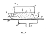
- the apparatus of Figure 4 illustrates an application of this invention to enable the production of acceptable air-laid web at a higher speed of production than previously possible.
- apparatus 18 comprises a conventional fiber distributor 20 positioned above a moving foraminous forming surface 22 moving from left to right in the drawing in the direction shown, with cellulosic fibers being impelled from the bottom 24 of the distributor 20 to form an air suspension of fibers directed toward the forming surface 22.
- a suction box 26 is positioned below the forming surface 22, offset somewhat in the downstream direction relative to the distributor 18, the suction box 26 in use creating a moving air stream downwardly through the forming surface 22 and out via an exhaust pipe 28 to a fan (not shown).
- the air stream fibers flow from the bottom 24 of the distributor box to the portion of the moving surface 22 above the suction box 26 where the fibers are deposited in the form of an air laid web 29.
- the individual fibers are brought onto the moving surface 22 at an oblique angle by means of both the action of the offset position of the suction box 26 as well as by air turning foils 30.
- the turning foils 30 are positioned adjacent the upstream end of the distributor 20 and generally serve to introduce a horizontal air stream into the stream of fibers flowing from the distributor 20 to the forming web 22.
- Sealing roll 32 is positioned along the downstream end of distributor 20 substantially to seal the space between the distributor 20 and the forming surface 22. Side seals, not shown, seal the sides of the apparatus. These seals reduce air loss and minimize air turbulence within the apparatus.
- the horizontal air stream introduced by the turning foils 30 coacts with the offset suction box 26 to impart a horizontal component of velocity to the fibers within the airstream.
- the dashed lines L in Fig. 4 indicate typical probable paths of fibers and illustrate that the fibers approach the moving surface 22 at an oblique angle having a velocity component in the direction of movement of the moving wire 22, thereby enabling the production of an acceptable air laid web at a higher speed of the forming surface 22 in accordance with this invention.
Landscapes
- Engineering & Computer Science (AREA)
- Textile Engineering (AREA)
- Nonwoven Fabrics (AREA)
Description
- This invention relates to methods for forming nonwoven fibrous webs, wherein a layer of fibers is deposited from a gaseous suspension of fibers onto a moving foraminous forming surface. More specifically, this invention provides improvements in methods of achieving high speed production of nonwoven fibrous webs.
- In the production of nonwoven webs, the prior art has generally disclosed systems which form an air suspension of fibers and direct the suspended fibers toward a moving foraminous forming surface upon which the fibers from the suspension are condensed-to form the nonwoven web. Various apparatuses exist for generating the air suspension of fibers. The fibers, for example, can be produced by a lickerin, a hammermill, or by other apparatus known in the art. The fibers can be dispersed in a gaseous medium by a variety of methods, and conveyed to a forming surface in an air stream operating generally as a pressure flow system, a vacuum system or a closed loop system. We have found that critical process limitations exist in the production of such air laid nonwoven webs, and that in a given system the uniformity of the formed web tends to decrease as the speed of the forming surface increases. It has been found that particularly at commercial speeds above about 550 feet per minute (2.79 meters per second), fiber lay-down on the moving forming surface tends to become uneven in the machine direction (i.e. the direction of travel of the forming surface). Thus the deposited webs exhibit an upper surface having an undulating, wave-like or ripple effect extending transverse to the machine direction, so that the webs exhibit corresponding variations in thickness and in weight. This rippling effect becomes more pronounced as the speed of the forming surface increases, with the spacing between the thicker portions of the web becoming greater and with the web becoming more varied along its surface as to basis weight. This rippling effect worsens with increased speed and eventually renders webs commercially unacceptable at some higher speed. This invention has sought to alleviate significantly the detrimental ripple effect. We have determined that there exists a critical relationship between the velocity of the fibers relative to the velocity of the moving forming surface as the fibers are being deposited onto the forming surface. We have found that the detrimental ripple effect can be controlled by controlling the ratio of the tangential velocity of the fibers relative to the moving forming surface, as compared to the velocity of the fibers normal to the moving surface.
- Prior art concerned with obtaining higher production speeds in the production of air laid webs includes U.S. Patent No. 4,004,323 wherein it is taught that speeds in excess of 200 feet per minute (1.01 m/sec) and even in excess of 400 feet per minute (2.03 m/sec) can be achieved by inclining a duct, which carries a stream of fibers, at an angle to a forming surface. The patent teaches a range of angles of incidence of the duct relative to the forming surface of from about 10° to about 30°. The patent fails, however, to report the high speed formation defect termed herein the rippling effect, and does not teach the criticality of the velocity ratios as between the fibers and the forming surface in alleviating the detrimental rippling effect. Indeed, the present invention teaches that there are combinations of fiber stream velocities and forming surface velocities for which ducts aligned as recommended in Gotchel will produce unacceptable webs with pronounced ripples.
- This invention relates to methods for forming a nonwoven fibrous web on a foraminous forming surface moving at a speed in excess of about 500 feet per minute (2.54 m/sec). The methods include dispersing the fibers uniformly in a gaseous medium to form a gaseous suspension of fibers. The gaseous suspension of fibers is conveyed in a stream to the moving forming surface onto which the fibers from the gaseous suspension are deposited to form a nonwoven fibrous web. The detrimental high-speed forming phenomenon termed the rippling effect is alleviated by controlling the critical relationship between the velocity of the fibers being deposited onto the moving forming surface, relative to the velocity of the latter.
- According to the present invention, there is provided a method for forming a nonwoven fibrous web from fibers of a papermaking length generally less than inch (6.35 mm), wherein the fibers are distributed in a gaseous medium to form a gaseous suspension of fibers and are thereafter deposited from the gaseous suspension onto a moving foraminous forming surface to form the nonwoven fibrous web, characterised by the steps of
- (a) moving the forming surface at a velocity Vo not less than 500 feet per minute (2.54 m/sec), and
- (b) conveying the gaseous fiber suspension in a stream to the moving forming surface, the gaseous stream having a velocity component V, in the direction of motion of the forming surface and a velocity component V2 normal to the forming surface, the magnitude of the difference between the forming surface velocity Vo and velocity component V, being less than 3 times the fiber velocity component V2.
- The forming surface onto which the fibers are deposited need not be planar, but could be curved, in which case it will have a tangential velocity Vo greater than 500 feet per minute (2.54 m/sec), the fiber velocity component V, being directed in the same direction as the motion of the curved forming surface.
- When the velocities meet this ratio of 3:1 or less, the air-laid product is generally acceptable in terms of the ripple effect; outside this ratio the air-laid product generally is unacceptable as having excessive ripple characteristics.
- In more complicated air/fiber flow patterns, wherein the gaseous stream containing the fibers has a further velocity component V3 in the cross machine direction, the magnitude of the relative velocity component of the gaseous stream tangential to the forming surface, V' is equal to the square root of the quantity (Vo - V1)2 plus (V3)2. In this case also, the velocity V' should be less than about three (3) times the fiber velocity V2.
- Operation within the critical relationship between the fiber velocities relative to the forming surface velocity can be implemented in a variety of ways. For a given velocity Vo of the forming surface, the normal fiber velocity V2 can be increased, for example by increasing the amount of suction pulling the gaseous stream through the moving surface. As a second example, the gaseous stream can be deflected to impinge upon the forming surface at an oblique angle, thereby increasing the velocity component Vl- of the gaseous stream in the direction of motion of the forming surface while maintaining velocity V2 constant by increasing the amount of suction. In either approach the ratio of the velocity of the fibers relative to the velocity of the moving forming surface, compared to the component of the fiber velocities normal to the forming surface, can be varied to produce more acceptable pro- ducts having more uniform web characteristics.
- The invention will now be described in more detail by way of non-limiting example, with reference to the accompanying drawings, in which:
- FIGURES 1A and 1B illustrate air laid webs produced at velocity ratios (as hereinbefore mentioned) of 2.5:1 and 3.5:1, respectively;
- FIGURES 2A and 2B are diagrams illustrating the ripple effect at velocity ratios of 1.3:1 and 4: 1, respectively;
- FIGURE 3 is a graph illustrating ripple wavelength for velocity ratios of from 1 : 1 to 5:1; and
- FIGURE 4 illustrates apparatus for use in practising this invention, with partial cutouts for clarity.
- We have found that the high speed production of air laid webs is severely limited by a nonuniformity of web formation herein termed the ripple effect. This invention aims at alleviating the detrimental ripple effect by controlling certain critical relationships between the velocity of fibers in a gaseous stream being condensed on a moving foraminous forming surface, relative to the velocity of the moving surface.
- Figures 2A and 2B illustrate two conditions of air laid web formation under two different velocity conditions as viewed relative to the
surface 12. In Figure 2A, typical fiber paths, 10, illustrate fibers approaching a formingsurface 12 at an overall relative velocity V (relative), relative to thesurface 12. As shown, this overall relative velocity V (relative) is how an oncoming fiber would be viewed from a stationary point riding on the movingsurface 12. The relative velocity, therefore, is the vector sum of the actual fiber velocity, here shown as V (actual) which has vector components V2 normal to the forming surface and V, parallel to the formingsurface 12. When viewed relative to the formingsurface 12 moving at a velocity Vo, the velocity V, component is subtracted from Vo to obtain the fiber velocity V' relative to thesurface 12. The magnitude of Vo - V, therefore represents the relative velocity of the oncoming fiber in a direction along the forming surface, and V2 represents the velocity of the oncoming fiber in the direction normal to the forming surface. We have determined that a critical parameter in the formation of a web as illustrated in Figure 1A is the ratio of V' to the fiber velocity V2 normal to the surface. We have found that in forming a nonwoven fibrous web substantially comprising fibers of a papermaking length generally less than inch (6.35 mm), this ratio must be maintained below about 3:1 to obtain acceptable product in terms of uniformity of the web, i.e. in terms of the inherent ripple effect. - Figure 2A further illustrates this ripple effect and our present belief of the reasons for the nonuniform web formation. Figure 2A illustrates a
nonwoven web 14 formed of fibers deposited, as illustrated, alongfiber paths 10. As the fibers are deposited on the formingsurface 12, the fibers approach the surface at an oblique angle as viewed in a coordinate system moving with the forming surface. The ripple is believed to be primarily caused by a "shadowing" effect caused by the oblique approach of the fibers to thesurface 12. This shadowing begins with the first fiber deposits, which occur randomly on thesurface 12. These fiber deposits cause "shadows" directly downstream from their positions generally preventing oncoming fibers from falling in the areas of the shadows. Fiber continues to accumulate directly upstream from these initial deposits such as inthicker web portions 13 until the shadowing influence of a neighboring upstream deposit interferes. With further fiber deposition there is an apparent linking up offiber deposits 13 in the cross machine direction to form the characteristic ripple effect. As is apparent from the Figure, this shadowing phenomenon produces the ripple effect withthicker web portions 13 alternating withthinner web portions 15. Further fiber deposition only increases the ripple characteristic of the web without changing the ripple wavelength. Except for some possible fiber bouncing or slipping during the initial deposition of fibers onto a surface, no fiber bouncing or slipping has been observed in the formation of webs below a velocity ratio of about 3:1. At ratios above about 3:1, fiber bouncing or slippage was observed to be a more significant forming phenomenon, with the resulting web exhibiting extremely nonuniform web characteristics. - Figures 2A and 2B illustrate the relation between the nonuniformity of web formation, i.e. the ripple effect, and the ratios between the fiber and forming surface velocities. In Figure 2A, V', the difference between velocity Vo of the
moving surface 12 and velocity component V, of the fibers in the direction of motion of the surface, is about one and three tenths (1.3) times the velocity V2 of the fibers normal to the moving surface, i.e. a velocity ratio- of 1.3. The resulting web, 14, is relatively uniform with closely spacedthicker web portions 13. In Figure 2B, the difference V' between velocity Vo of the movingsurface 12B and velocity component V, of the fibers in the direction of motion of the surface, is about four times that of velocity V2 of the fibers normal to the moving surface 12g, (a velocity ratio of 4:1) and the-resultingweb 14B is much less uniform than theweb 14 of Figure 2A, with a more pronounced ripple effect, i.e. with thethicker portions 13B of the web more widely spaced and of greater relative basis weight than in theweb 14 of 2A. - Figures 2A and 2B illustrate fiber velocities only having components V, in the direction of motion of the forming surface and V2 normal to the forming surface. No fiber velocity components in the cross-machine direction, i.e. perpendicular both to velocity component V, and to velocity component V2, have been illustrated since such velocity components are generally undesirable in the manufacture of air laid webs. In instances where such cross-machine velocity components do in fact exist, such velocity components V3 may affect the web formation since those cross-machine velocity components will increase the relative velocity V' by the following formula, V' is equal to the square root of (Vo - V,)2 + (V3)2, and thereby. affect the velocity ratio V':V2. Such cross machine velocities V3 may deleteriously affect the web, requiring corresponding adjustments to reduce V' or increase V2 in those affected web areas.
- Figures 1A and 1B are plan views of webs formed at velocity ratios of 2.5:1 and 3.5:1, respectively. As seen in Figure 1A, at the lower 2.5:1 ratio, the web produced is relatively uniform, exhibiting the ripple effect to a minor, but acceptable degree. Some variation in fiber deposit is evident, with recurring heavier deposits at, for example, 17A, 17B, 17C. As seen in Figure 1A, the distances between these uniformly recurring
heavier deposits - Figure 3 is a graph illustrating experimental results of studies as to the ripple effect, for velocity ratios (V0 ― V1 : V2) ranging from 1:1 to 5:1. These studies were conducted using softwood Kraft and included studies of other variables in the air laid forming process in order to verify the criticality of this velocity ratio parameter.
- The tests verified that the ratio results as illustrated by Figure 3 are independent of the absolute speeds involved, from about 250 feet per minute (1.27 m/sec) up to a forming surface speed of about 2250 feet per minute (11.43 m/sec). It is believed that the ratio results are independent of speed at speeds lower than 250 feet per minute (1.27 m/sec) and greater than 2250 feet per minute (11.43 m/sec). Other tests verified that the ratio results as illustrated by Figure 3 are generally independent of the foraminous forming surface used for web formation at ratios of below 3:1. Most of the tests were conducted using a 59 (MD) x 42 (CD) brass forming wire, 0.0095 inch (MD) (0.241 mm) and 0.0115 inch (CD) (0.292 mm) in diameter. Other tests verifying these ratio results were conducted on wires: 40 (MD) x 32 (CD), bronze, 0.0112 inch (MD) (0.284 mm) x 0.0125 inch (CD) (0.317 mm); 78 (MD) x 64 (CD), bronze, 0.0067 inch (MD) (0.170 mm) x 0.00725 inch (CD) (0.0184 mm), 108 (MD) x 64 (CD) double-weave polyester 0.00866 inch (MD) (0.220 mm) x 0.00866 (CD), top, and 0.0118 (CD) (0.300 mm) bottom; and 84 (MD) x 32 (CD) two-layer polyester, 0.0157 inch (MD) (0.399 mm) x 0.0157 inch (CD) (0.399 mm). In the foregoing, the numbers preceding "(MD)" and "(CD)" refer to the number of mesh openings per inch (25.4 mm), considered in the direction of motion of the forming surface and transverse to this direction, respectively.
- As shown in Figure 3, up to the critical velocity ratio of approximately 3: 1, the ripple wavelength, as defined above, increases to a minor degree with an increase in the velocity ratio. Air laid fibrous product produced under conditions of a velocity ratio of 3:1 or less, was generally considered to be acceptable in terms of uniformity of web density. Product produced at conditions of greater than a 3:1 velocity ratio was judged unacceptable in that the variances in web basis weight and thickness, the ripple effect, were too great. As seen in the graph of Figure 3, above the 3:1 ratio the variation in web characteristics becomes extremely disproportionate to a variation in velocity ratio, thereby establishing the criticality of the 3:1 limit.
- Most of the studies establishing the criticality of the velocity ratio of 3:1 were conducted using softwood Kraft fibers which are relatively long cellulosic natural fibers. Use of fibers of other sizes would vary the ripple effect in terms of the wavelength but would not affect the criticality of the 3:1 ratio. For example, use of a shorter natural fiber such as a hardwood fiber, will cause less of the shadowing problem and will tend to shorten the wavelength in the web for a given velocity ratio.
- Since lowering the velocity ratio will lower the ripple wavelength for a given length of fibers, the actual ratio at which the fibrous product is produced for commercial application can be varied to obtain a desired product. For example, it may be desired to produce fibrous product comprised substantially of softwood Kraft fibers at a velocity ratio of 2.5:1 for commercial purposes since that product would exhibit more uniform web characteristics than if produced at a 3:1 velocity ratio. Similarly, the fibrous product could be varied as to its composition, varying the fiber sizes to vary the ripple effect at a given velocity ratio. For example, a mixture of hardwood and softwood fibers might constitute commercially acceptable fibrous product at a higher velocity ratio than for a product produced primarily of softwood fibers.
- As stated above, the wavelength of the ripple effect is independent of the overall basis weight of the deposited web. As the web is being deposited onto the forming surface, the spacing between the thicker portions of the web (the ripple wavelength) is established early during the deposition of the fibers, and further fiber deposition only increases the web thickness without affecting this ripple wavelength. For commercial purposes, a lower weight web, such as a tissue product, might be produced at a lower velocity ratio to shorten the ripple wavelength, obtaining a more satisfactory commercial product in terms of minimizing the effect of the
thinner web portions 15. It is believed that this invention can be used to produce air laid webs at least in the range of from about 7 to about 75 pounds (3.17 to 34.01 kg) per 3000 square feet of web (278.7 sq. meters). The weight of fibers distributed over this area can be in the range 25 to 70 pounds (11.3 to 31.7 kg), for instance 30 to 45 pounds (13.6 to 20.4 kg). - The apparatus of Figure 4 illustrates an application of this invention to enable the production of acceptable air-laid web at a higher speed of production than previously possible.
- In Figure 4,
apparatus 18 comprises aconventional fiber distributor 20 positioned above a movingforaminous forming surface 22 moving from left to right in the drawing in the direction shown, with cellulosic fibers being impelled from the bottom 24 of thedistributor 20 to form an air suspension of fibers directed toward the formingsurface 22. Asuction box 26 is positioned below the formingsurface 22, offset somewhat in the downstream direction relative to thedistributor 18, thesuction box 26 in use creating a moving air stream downwardly through the formingsurface 22 and out via anexhaust pipe 28 to a fan (not shown). - The air stream fibers flow from the bottom 24 of the distributor box to the portion of the moving
surface 22 above thesuction box 26 where the fibers are deposited in the form of an air laidweb 29. In this stream of fibers, the individual fibers are brought onto the movingsurface 22 at an oblique angle by means of both the action of the offset position of thesuction box 26 as well as by air turning foils 30. The turning foils 30 are positioned adjacent the upstream end of thedistributor 20 and generally serve to introduce a horizontal air stream into the stream of fibers flowing from thedistributor 20 to the formingweb 22. Sealingroll 32 is positioned along the downstream end ofdistributor 20 substantially to seal the space between thedistributor 20 and the formingsurface 22. Side seals, not shown, seal the sides of the apparatus. These seals reduce air loss and minimize air turbulence within the apparatus. - The horizontal air stream introduced by the turning foils 30 coacts with the offset
suction box 26 to impart a horizontal component of velocity to the fibers within the airstream. The dashed lines L in Fig. 4 indicate typical probable paths of fibers and illustrate that the fibers approach the movingsurface 22 at an oblique angle having a velocity component in the direction of movement of the movingwire 22, thereby enabling the production of an acceptable air laid web at a higher speed of the formingsurface 22 in accordance with this invention.
Claims (9)
Priority Applications (2)
| Application Number | Priority Date | Filing Date | Title |
|---|---|---|---|
| EP19810301272 EP0060948B1 (en) | 1981-03-25 | 1981-03-25 | Methods for forming nonwoven fibrous webs |
| DE8181301272T DE3169320D1 (en) | 1981-03-25 | 1981-03-25 | Methods for forming nonwoven fibrous webs |
Applications Claiming Priority (1)
| Application Number | Priority Date | Filing Date | Title |
|---|---|---|---|
| EP19810301272 EP0060948B1 (en) | 1981-03-25 | 1981-03-25 | Methods for forming nonwoven fibrous webs |
Publications (2)
| Publication Number | Publication Date |
|---|---|
| EP0060948A1 EP0060948A1 (en) | 1982-09-29 |
| EP0060948B1 true EP0060948B1 (en) | 1985-03-20 |
Family
ID=8188248
Family Applications (1)
| Application Number | Title | Priority Date | Filing Date |
|---|---|---|---|
| EP19810301272 Expired EP0060948B1 (en) | 1981-03-25 | 1981-03-25 | Methods for forming nonwoven fibrous webs |
Country Status (2)
| Country | Link |
|---|---|
| EP (1) | EP0060948B1 (en) |
| DE (1) | DE3169320D1 (en) |
Families Citing this family (1)
| Publication number | Priority date | Publication date | Assignee | Title |
|---|---|---|---|---|
| CN110965204B (en) * | 2019-12-10 | 2024-10-18 | 广东五源新材料科技集团有限公司 | Auto-leveling web forming device, method and product for suction coating and free falling |
Family Cites Families (2)
| Publication number | Priority date | Publication date | Assignee | Title |
|---|---|---|---|---|
| US3755856A (en) * | 1971-04-23 | 1973-09-04 | Kimberly Clark Co | Method and apparatus for the formation of fiber fluff |
| FI760157A7 (en) * | 1976-01-23 | 1977-07-24 | Risto Tiitola |
-
1981
- 1981-03-25 DE DE8181301272T patent/DE3169320D1/en not_active Expired
- 1981-03-25 EP EP19810301272 patent/EP0060948B1/en not_active Expired
Also Published As
| Publication number | Publication date |
|---|---|
| DE3169320D1 (en) | 1985-04-25 |
| EP0060948A1 (en) | 1982-09-29 |
Similar Documents
| Publication | Publication Date | Title |
|---|---|---|
| US2931076A (en) | Apparatus and method for producing fibrous structures | |
| US3906588A (en) | Air-laydown apparatus for assembling fibers into webs | |
| CA1049731A (en) | Web forming apparatus and method | |
| EP0224892B1 (en) | Method and apparatus for producing a continuous web | |
| US3994047A (en) | Apparatus for the twin-wire air laying of fibrous pads | |
| CA1074603A (en) | Method of and means for papermaking with high consistency fiber suspensions | |
| JPS63275764A (en) | Production of spun yarn fleece composed of synthetic endless filament | |
| US4276248A (en) | Methods for forming fibrous webs | |
| US4359445A (en) | Method for producing a lofted mat | |
| US4292365A (en) | Polymeric mats having continuous filaments with an asymmetrical cross-sectional shape | |
| US3296066A (en) | Headbox for papermaking machine and stock distributor thereto | |
| EP0006327A1 (en) | Apparatus for distributing fibres uniformly over a conveyor surface | |
| US3954558A (en) | Feeding device for paper machines | |
| EP0060948A1 (en) | Methods for forming nonwoven fibrous webs | |
| CA1042174A (en) | Fiber distribution and depositing apparatus | |
| EP0115272B1 (en) | Improved apparatus for forming dry laid webs | |
| US5968557A (en) | Apparatus for manufacturing spun-bonded webs | |
| US7008205B2 (en) | Installation for producing a spunbonded fabric web whereof the diffuser is distant from the drawing slot device | |
| US4627953A (en) | Method for forming dry laid webs | |
| CA1046816A (en) | Flowboxes | |
| US4270888A (en) | Apparatus for producing filaments | |
| CA2044734A1 (en) | Headbox | |
| FI112097B (en) | forming device | |
| US3578556A (en) | Vertical paper machine wherein stock impinges wires below the breast rolls | |
| US4766649A (en) | Papermaker's felt utilizing special web-making techniques to avoid vibration |
Legal Events
| Date | Code | Title | Description |
|---|---|---|---|
| PUAI | Public reference made under article 153(3) epc to a published international application that has entered the european phase |
Free format text: ORIGINAL CODE: 0009012 |
|
| AK | Designated contracting states |
Designated state(s): DE FR SE |
|
| RAP1 | Party data changed (applicant data changed or rights of an application transferred) |
Owner name: JAMES RIVER-DIXIE/NORTHERN INC. |
|
| 17P | Request for examination filed |
Effective date: 19830305 |
|
| GRAA | (expected) grant |
Free format text: ORIGINAL CODE: 0009210 |
|
| AK | Designated contracting states |
Designated state(s): DE FR SE |
|
| REF | Corresponds to: |
Ref document number: 3169320 Country of ref document: DE Date of ref document: 19850425 |
|
| RAP2 | Party data changed (patent owner data changed or rights of a patent transferred) |
Owner name: JAMES RIVER-NORWALK, INC. |
|
| ET | Fr: translation filed | ||
| PLBE | No opposition filed within time limit |
Free format text: ORIGINAL CODE: 0009261 |
|
| STAA | Information on the status of an ep patent application or granted ep patent |
Free format text: STATUS: NO OPPOSITION FILED WITHIN TIME LIMIT |
|
| 26N | No opposition filed | ||
| PGFP | Annual fee paid to national office [announced via postgrant information from national office to epo] |
Ref country code: FR Payment date: 19910211 Year of fee payment: 11 |
|
| PGFP | Annual fee paid to national office [announced via postgrant information from national office to epo] |
Ref country code: SE Payment date: 19910218 Year of fee payment: 11 |
|
| PGFP | Annual fee paid to national office [announced via postgrant information from national office to epo] |
Ref country code: DE Payment date: 19910228 Year of fee payment: 11 |
|
| PG25 | Lapsed in a contracting state [announced via postgrant information from national office to epo] |
Ref country code: SE Effective date: 19920326 |
|
| PG25 | Lapsed in a contracting state [announced via postgrant information from national office to epo] |
Ref country code: FR Effective date: 19921130 |
|
| PG25 | Lapsed in a contracting state [announced via postgrant information from national office to epo] |
Ref country code: DE Effective date: 19921201 |
|
| REG | Reference to a national code |
Ref country code: FR Ref legal event code: ST |
|
| EUG | Se: european patent has lapsed |
Ref document number: 81301272.1 Effective date: 19921005 |