EP0060140A1 - Scroll type compressor with displacement adjusting mechanism - Google Patents
Scroll type compressor with displacement adjusting mechanism Download PDFInfo
- Publication number
- EP0060140A1 EP0060140A1 EP82301205A EP82301205A EP0060140A1 EP 0060140 A1 EP0060140 A1 EP 0060140A1 EP 82301205 A EP82301205 A EP 82301205A EP 82301205 A EP82301205 A EP 82301205A EP 0060140 A1 EP0060140 A1 EP 0060140A1
- Authority
- EP
- European Patent Office
- Prior art keywords
- holes
- end plate
- wrap
- scroll
- fluid
- Prior art date
- Legal status (The legal status is an assumption and is not a legal conclusion. Google has not performed a legal analysis and makes no representation as to the accuracy of the status listed.)
- Granted
Links
Images


Classifications
-
- F—MECHANICAL ENGINEERING; LIGHTING; HEATING; WEAPONS; BLASTING
- F04—POSITIVE - DISPLACEMENT MACHINES FOR LIQUIDS; PUMPS FOR LIQUIDS OR ELASTIC FLUIDS
- F04C—ROTARY-PISTON, OR OSCILLATING-PISTON, POSITIVE-DISPLACEMENT MACHINES FOR LIQUIDS; ROTARY-PISTON, OR OSCILLATING-PISTON, POSITIVE-DISPLACEMENT PUMPS
- F04C28/00—Control of, monitoring of, or safety arrangements for, pumps or pumping installations specially adapted for elastic fluids
- F04C28/10—Control of, monitoring of, or safety arrangements for, pumps or pumping installations specially adapted for elastic fluids characterised by changing the positions of the inlet or outlet openings with respect to the working chamber
- F04C28/16—Control of, monitoring of, or safety arrangements for, pumps or pumping installations specially adapted for elastic fluids characterised by changing the positions of the inlet or outlet openings with respect to the working chamber using lift valves
-
- Y—GENERAL TAGGING OF NEW TECHNOLOGICAL DEVELOPMENTS; GENERAL TAGGING OF CROSS-SECTIONAL TECHNOLOGIES SPANNING OVER SEVERAL SECTIONS OF THE IPC; TECHNICAL SUBJECTS COVERED BY FORMER USPC CROSS-REFERENCE ART COLLECTIONS [XRACs] AND DIGESTS
- Y10—TECHNICAL SUBJECTS COVERED BY FORMER USPC
- Y10T—TECHNICAL SUBJECTS COVERED BY FORMER US CLASSIFICATION
- Y10T137/00—Fluid handling
- Y10T137/8593—Systems
- Y10T137/877—With flow control means for branched passages
- Y10T137/87708—With common valve operator
- Y10T137/87772—With electrical actuation
Definitions
- This invention relates to a compressor, and more particularly, to a scroll type compressor for an air conditioning apparatus which includes a mechanism for adjusting the displacement of the compressor.
- Scroll type fluid displacement apparatus are well known in the prior art.
- U.S. Patent No. 801,182 discloses a device including two scrolls each having a circular end plate and a spiroidal or involute spiral element. These scrolls are maintained angularly and radially offset so that both spiral elements interfit to make a plurality of line contacts between their spiral curved surfaces to thereby seal off and define at least one pair of fluid pockets.
- the relative orbital motion of the two scrolls shifts the line contact along the spiral -curved surfaces and, as a result, the volume of the fluid pockets changes. Since the volume of the fluid pockets increases or decreases dependent on the direction of the orbital motion, the scroll type fluid apparatus is applicable to compress, expand or pump fluids.
- Scroll type fluid displacement apparatus are suitable for use as refrigerant compressors in air conditioners.
- thermal control in the room or control of air conditioner is generally accomplished by intermittent operation of the compressor which in turn is activated or controlled by a signal from a thermostat located in the room being cooled.
- the refrigerant capacity of the air conditioner for supplemental cooling because of further temperature changes in the room, or for keeping the room at the desired temperature, generally need not be very large.
- prior art air conditioners do not have capacity control mechanisms. Therefore, after the room has been cooled to the desired temperature, the manner for controlling the output of the compressor is by intermittent operation of the compressor.
- the relatively large load, which is required to drive the compressor, is thus intermittently applied to the driving source.
- the compressor When the compressor is used in an automotive air conditioner, it is driven by the engine of automobile through a electromagnetic clutch.
- Such prior art automotive air conditioners face the same output problem once the passenger compartment reaches a desired temperature. Control of the compressor's output is accomplished by intermittent operation of the compressor through a magnetic clutch which connects the automobile engine to the compressor.
- the relatively large load, which is required to drive the compressor is thus intermittently applied to the automobile engine.
- a scroll type compressor including a pair of scroll members each having an em plate and a wrap extending from one. side surface of said end plate, said wraps interfitting at angular and radial offset to make a plurality of line contacts between said wraps to define at least one pair of sealed off fluid pockets, and a driving mechanism operatively connected to one of said scroll members for orbiting said one scroll member relatively to the other scroll member while preventing rotation of said one scroll member to thereby change the volume of the fluid pockets, characterised by one of said end plates having at least one pair of holes through it to place opposite sides of said one end plate in fluid communication through said holes, said holes being located at symmetrical locations along the wrap which extends from the said one end plate so that said other wrap simultaneously crosses over both of said holes, a first of said holes being located within an area defined by end ⁇ > ⁇ 1 > 0end - 2 ⁇ , where ⁇ end is the final involute angle of the wrap extending from the said one end plate through which said holes are formed
- a preferred scroll type compressor includes a pair of scrolls.
- Each scroll includes an end plate and a wrap extending from one side surface of the end plate.
- the wraps interfit at an angular and radial offset to make a plurality of line contacts and define at least one pair of sealed off fluid pockets.
- One of the scrolls (an orbiting scroll) is driven in orbital motion by the rotation of a drive shaft, while the rotation of the orbiting scroll is prevented.
- the fluid pockets shift along the spiral curved surface of the wrap to change the volume of the fluid pockets.
- One of the end plates has at least a pair of holes formed through it. The holes are placed in symmetrical positions so that the wrap of the other scroll member simultaneously crosses over the holes.
- a first of the holes is placed within an area defined by ⁇ end > ⁇ 1 7 ⁇ end - 2TT , where ⁇ end is the final involute angle of the wrap which extends from the end plate having the holes, and ⁇ 1 is the involute angle at which the hole is located.
- a control device controls the opening and closing of the holes.
- the displacement volume of the fluid pockets is controlled by opening and closing the holes with the control device. When the holes are closed compression operates normally and the displacement volume is not changed.
- the holes are opened by the control device, fluid in the sealed off pockets flows back into the suction chamber through the holes until the spiral element of the other scroll crosses over the holes. The displacement volume in the fluid pockets is thereby reduced, and compression starts at an intermediate stage.
- the compressor 1 includes a compressor housing 10 having a front end plate 11 and a cup shaped casing 12 which is attached to an end surface of front end plate 11.
- An opening III is formed in the center of front end plate 11 for the penetration or passage of a drive shaft 13.
- An annular projection 112 is formed in a rear end surface of front end plate member 11. Annular projection 112 faces cup shaped casing 12 and is concentric with opening lll. An outer peripheral surface of annular projection 112 extends into an inner wall of the opening of cup shaped casing 12.
- Cup shaped casing 12 is fixed on the rear end surface of front end plate II by a fastening device for example, bolts and nuts. The opening of cup shaped casing 12 is thus covered by front end plate II.
- An O-ring 14 is placed between the outer peripheral surface of annular projection 112 and the inner wall of the opening of cup shaped casing 12 to seal the mating surfaces of front end plate 11 and cup shaped casing 12.
- Front end plate II has an annular sleeve 15 projecting from the front end surface thereof which surrounds drive shaft 13 and defines a shaft seal cavity.
- sleeve 15 is separate from end plate member 11. Therefore, sleeve 15 is fixed to the front end surface of front end plate 11 by screws 16.
- An O-ring is placed between the end surface of front end plate 11 and the end surface of sleeve 15 to seal the mating surfaces of front end plate 11 and sleeve 15.
- sleeve 15 may be integral with front end plate ll.
- Drive shaft 13 is rotatably supported by sleeve 15 through a bearing 18 located within the front end of sleeve 15.
- Drive shaft 13 has a disk 19 at its inner end which is rotatably supported by front end plate member 11 through a bearing 20 located within opening III of front end plate ll.
- a shaft seal assembly 21 is coupled to drive shaft 13 within the shaft seal cavity of sleeve 15.
- a pulley 22 is rotatably supported by a bearing assembly 23 which is carried on the outer surface of sleeve 15.
- An electromagnetic coil 2 4 is fixed about the outer surface of sleeve 15 by a support plate 25 and is received in an annular cavity of pulley 22.
- An armature plate 26 is elastically supported on the outer end of drive shaft 13 which extends from sleeve 15.
- a magnetic clutch thus includes pulley 22 magnetic coil 24, and armature plate 26. In operation, drive shaft is driven by an external power source, for example the engine of an automobile, through a rotation transmitting device such as the magnetic clutch.
- a fixed scroll 27, an orbiting scroll 28, a driving mechanism of orbiting scroll 28, and a rotation preventing mechanism for orbiting scroll 28 are located in an inner chamber of cup shaped casing 12.
- Fixed scroll 27 includes a circular end plate 271, a wrap or spiral element 272 affixed to or extending from one side surface of end plate 27L
- a partition wall 273" axially projects from the opposite side surface of circular end plate 271.
- An axial end surface of partition wall 273 is seated against and connected to an inner surface of end plate portion 121 of cup shaped casing 12 by fasteners (not shown).
- Circular end plate 271 of fixed scroll member 27 partitions the inner chamber of cup shaped casing 12 into a first chamber 29 and a second chamber 30.
- a seal ring 31 is placed between the outer peripheral surface of end plate 271 and the inner wall of cup shaped casing 12 to form a seal between the mating surfaces.
- Spiral element 272 of fixed scroll member 27 is located within first chamber 29 and partition wall 273 is located within second chamber 30.
- Partition wall 273 further divides second chamber 30 into a suction chamber 301 and a discharge chamber 302.
- Orbiting scroll 28 is located in first chamber 29 and also includes a circular end plate 281 and a wrap or spiral element 282 affixed to or extending from one side surface of end plate 281. Spiral elements 272 and 282 interfit at an angular offset of 180 0 and a predetermined radial offset. At least a pair of sealed off fluid pockets are thereby defined between the spiral elements 272 and 282.
- Orbiting scroll 28 is rotatably supported by a bushing 31 through a bearing placed on the outer peripheral surface of bushing 31.
- Bushing 31 is connected to an inner end of disk 19 at a point radially offset or eccentric of the axis of drive shaft 13.
- a rotation preventing/thrust bearing device 33 is placed between the inner end surface of front end plate 11 and the end surface of end plate 281 which faces the inner end surface of front end plate ll.
- Rotation preventing/thrust bearing device 33 includes a fixed ring 331 attached to the inner end surface of front end plate member ll, an orbiting ring 332 attached to the end surface of end plate 281, and a plurality of bearing elements, such as balls 333 placed between pockets 3 3 1a, 332a through rings 331 and 332.
- the rotation of orbiting scroll 2 8 during its orbital motion is prevented by the interaction of balls 333 with rings 331, 332; and the axial thrust load from orbiting scroll 28 is supported on front end plate II through balls 333.
- Cup shaped casing 12 has an inlet port 34 and outlet port 35 for connecting the compressor unit with an external fluid circuit. Fluid is introduced from the external circuit into suction chamber 301 through -.. inlet port 34 and flows into chamber 29 through a connecting hole formed through end plate 271 at a position near its outer peripheral surface. The fluid in chamber 29 is taken into the fluid pockets formed between spiral element 272 and 282. As orbiting scroll 28 orbits, the fluid in the fluid pockets moves to the center of spiral elements and is compressed. The compressed fluid is discharged into discharge chamber 302 from the fluid pockets in the general area of the center of the spiral elements through a hole 274 formed through circular end plate 271. The compressed fluid is then discharged to the external fluid circuit through outlet port 35.
- fluid is generally taken into the fluid pockets formed between spiral element 272 and 282 -through two open spaces.
- Each open space is defined between the outer terminal end of one of the spiral elements and the outer wall surface of the other spiral element.
- the entrance to these open spaces seqentially open and close during the orbital motion of orbiting scroll 28. While the entrances to these open spaces remain open, fluid to be compressed flows into them, but no compression occurs. After the entrances to the open spaces close, the sealed off fluid pockets are formed, no additional fluid flows into the pockets, and compression begins.
- the location of the outer terminal end of each spiral element 272 and 282 is at the final involute angle, therefore, the location of these open spaces is directly related to the final involute angle.
- At least one pair of holes 275 and 276 are formed in end plate 272 of fixed scroll 27 and are placed at symmetrical positions so that an axial end surface of spiral element 282 of orbiting scroll member 28 simultaneously crosses over holes 275 and 276.
- Hole 275 communicates between suction chamber 301 and one of the fluid pockets A
- hole 276 communicates between suction chamber 301 and the other fluid pocket A'.
- Hole 275 is placed at a position defined by the involute angle ⁇ and opens along the inner wall side of spiral element 272.
- ⁇ 1 is the involute angle location of the first hole, which is nearest the final involute angle ( ⁇ end) at the end of spiral element 272.
- the other hole 276 is placed at a position defined by the involute angle ( ⁇ 1- ⁇ ) and opens along the outer wall side of spiral element 272.
- the preferred area within which to place the first hole 275, as defined in involute angles, is given by ⁇ end > ⁇ 1> ⁇ end-2 ⁇ .
- the other hole 276 is located further from ⁇ end, i.e., at ⁇ 1- ⁇ .
- Holes 275 and 276 are formed by drilling into end plate 271 from the side opposite from which spiral element 272 extends. Hole 275 is drilled at a position which overlaps with the inner wall of spiral element 272, so that portion of the inner wall of spiral element 272 is removed. Hole 276 is drilled at a position which overlaps the outer wall of spiral element 272 so that a portion of the outer wall of spiral element 272 is removed. This overlapping of hole 275 is shown in detail in Fig. 3. In this arrangement, the axial end surface of each spiral element is provided with a seal which forms an axial seal between the spiral element and facing end plate. Holes 275 and 276 are positioned so that they do not connect with the fluid pockets between the spiral elements when spiral element 282 completely overlaps the holes.
- Control mechanism 37 is located in suction chamber 301 and connected to the outer peripheral surface of partition wall 273.
- Control mechanism 37 includes a value member having a plurality of valve plates 371 which are attached to the end surface of end plate 271 at each hole 275 and 276, and an annular shaped electromagnetic coil 3 7 2 attached to the outer surface of partition wall 273.
- Each valve plate 371 is made of a spring type magnetic material, and is attached to the end surface of end plate 271 by a fastener, such as a screw 38.
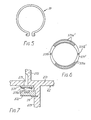
- Magnetic coil 37 is fitted into a groove 277 formed on the outer peripheral surface of partition wall 273, and is held therein against axial movement by a snap ring 39, as shown in Fig. 5.
- the inherent spring tendency of each valve plate 371 pushes it against the opening of. a respective hole 275, 276 to thus close the opening of each hole.
- Valve plates 371 are controlled by the operation of magnetic coil 372. By activating coil 372 the valve plates 371 are bent away from the openings in holes 275 and 276. Deactivating coil 372 permits the valve plates to again seal the openings to the holes because of their inherent spring tendency.
- Magnetic coil 372 is provided with contact portions 372a at its end surface facing the valve plates 371. When valve plates 371 are drawn away from holes 275 and 276 by magnetic coil 372, they contact portions 372a.
- Figs. 6 and 7 illustrate another embodiment of the valve member.
- the valve member is formed as an annular valve plate 371 1 which has an inherent spring property or tendency.
- Contact portions 371a' extend from the end surface of plate 371' opposite to magnetic coil 372 and serve as contact points with coil 372.
- Valve plate 371' is fixed on the end surface of end plate 271 by two screws (not shown) which pass through holes 371b' in valve plate 371'.
- Valve plate 371' is held in sealing contact against the openings of holes 275 and 276 by its inherent spring property. However, when coil 372 is energized, valve plate 371' bends against its inherent spring property and holes 275 and 276 open.
- valve member 371 When valve member 371 is attracted to magnetic coil 372 by its activation, each hole 275 and 276 is opened.
- fluid which has been taken into the sealed off fluid pocekts leaks from the sealed off fluid pockets A, A' back to suction chamber 301 during the orbital motion of orbiting scroll 28 from the position shown in Fig. 8a to the position shown in Fig. 8b.
- compression can not begin. This leaking continues until the axial end surface of spiral element 282 of orbiting scroll 28 crosses over and closes holes 275 and 276, this state being shown in Fig. 8c.
- the involute angle location of first hole 275 is given by 0 I > ⁇ end-2 ⁇ .
Abstract
Description
- This invention relates to a compressor, and more particularly, to a scroll type compressor for an air conditioning apparatus which includes a mechanism for adjusting the displacement of the compressor.
- Scroll type fluid displacement apparatus are well known in the prior art. For example, U.S. Patent No. 801,182 (Creux) discloses a device including two scrolls each having a circular end plate and a spiroidal or involute spiral element. These scrolls are maintained angularly and radially offset so that both spiral elements interfit to make a plurality of line contacts between their spiral curved surfaces to thereby seal off and define at least one pair of fluid pockets. The relative orbital motion of the two scrolls shifts the line contact along the spiral -curved surfaces and, as a result, the volume of the fluid pockets changes. Since the volume of the fluid pockets increases or decreases dependent on the direction of the orbital motion, the scroll type fluid apparatus is applicable to compress, expand or pump fluids.
- Scroll type fluid displacement apparatus are suitable for use as refrigerant compressors in air conditioners. In such air conditioners, thermal control in the room or control of air conditioner is generally accomplished by intermittent operation of the compressor which in turn is activated or controlled by a signal from a thermostat located in the room being cooled. Once the temperature in the room has been cooled down to a desired temperature, the refrigerant capacity of the air conditioner for supplemental cooling because of further temperature changes in the room, or for keeping the room at the desired temperature, generally need not be very large. However, prior art air conditioners do not have capacity control mechanisms. Therefore, after the room has been cooled to the desired temperature, the manner for controlling the output of the compressor is by intermittent operation of the compressor. The relatively large load, which is required to drive the compressor, is thus intermittently applied to the driving source. When the compressor is used in an automotive air conditioner, it is driven by the engine of automobile through a electromagnetic clutch. Such prior art automotive air conditioners face the same output problem once the passenger compartment reaches a desired temperature. Control of the compressor's output is accomplished by intermittent operation of the compressor through a magnetic clutch which connects the automobile engine to the compressor. The relatively large load, which is required to drive the compressor, is thus intermittently applied to the automobile engine.
- It is a primary object of this invention to provide an improvement in a scroll type compressor by incorporating a mechanism for changing the compression ratio of the compressor as occasion demands without the loss of energy consumption.
- It is another object of this invention to provide a scroll type compressor in which sealing of the fluid pockets is maintained while achieving the above object.
- According to the present invention there is provided a scroll type compressor including a pair of scroll members each having an em plate and a wrap extending from one. side surface of said end plate, said wraps interfitting at angular and radial offset to make a plurality of line contacts between said wraps to define at least one pair of sealed off fluid pockets, and a driving mechanism operatively connected to one of said scroll members for orbiting said one scroll member relatively to the other scroll member while preventing rotation of said one scroll member to thereby change the volume of the fluid pockets, characterised by one of said end plates having at least one pair of holes through it to place opposite sides of said one end plate in fluid communication through said holes, said holes being located at symmetrical locations along the wrap which extends from the said one end plate so that said other wrap simultaneously crosses over both of said holes, a first of said holes being located within an area defined by end Ø > Ø 1 > 0end - 2π, where Ø end is the final involute angle of the wrap extending from the said one end plate through which said holes are formed and Ø 1 is the involute angle at which said first hole is located, the other of said holes being located at an involute angle of approximately Ø 1 -π, and control means for selectively opening and closing said holes to permit fluid communication therethrough and to selectively control the displacement volume of said compressor.
- A preferred scroll type compressor according to this invention includes a pair of scrolls. Each scroll includes an end plate and a wrap extending from one side surface of the end plate. The wraps interfit at an angular and radial offset to make a plurality of line contacts and define at least one pair of sealed off fluid pockets. One of the scrolls (an orbiting scroll) is driven in orbital motion by the rotation of a drive shaft, while the rotation of the orbiting scroll is prevented. The fluid pockets shift along the spiral curved surface of the wrap to change the volume of the fluid pockets. One of the end plates has at least a pair of holes formed through it. The holes are placed in symmetrical positions so that the wrap of the other scroll member simultaneously crosses over the holes. A first of the holes is placed within an area defined by Ø end > Ø 1 7 Ø end - 2TT , where ø end is the final involute angle of the wrap which extends from the end plate having the holes, and Ø 1 is the involute angle at which the hole is located. A control device controls the opening and closing of the holes. The displacement volume of the fluid pockets is controlled by opening and closing the holes with the control device. When the holes are closed compression operates normally and the displacement volume is not changed. When the holes are opened by the control device, fluid in the sealed off pockets flows back into the suction chamber through the holes until the spiral element of the other scroll crosses over the holes. The displacement volume in the fluid pockets is thereby reduced, and compression starts at an intermediate stage.
- The invention will now be described, by way of example, with reference to the accompanying drawings, in which:-
- Fig. 1 is a vertical sectional view of a scroll type compressor unit according to an embodiment of this invention;
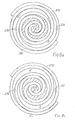
- Fig. 2 is a front end view of the fixed scroll member used in the compressor.of Fig. 1;
- Fig. 3 is a sectional view of the spiral elements illustrating the hole extending into one of the spiral elements;
- Fig. 4 is a perspective view of a magnetic coil used in the compressor of Fig. 1;
- Fig. 5 is a front end view of a snap ring used in the compressor of Fig. 1;
- Fig. 6 is a front end view of a valve mechanism according to another embodiment of this invention; and
- Fig. 7 is a sectional view of a control mechanism according to another embodiment of this invention; and
- Figs. 8a-8c are schematic views illustrating the operation of volume changing mechanism utilizing a'pair of holes.
- Referring to Fig. 1, a refrigerant compressor in accordance with an embodiment of the present invention, in particular, a scroll type refrigerant compressor 1 is shown. The compressor 1 includes a compressor housing 10 having a
front end plate 11 and a cup shapedcasing 12 which is attached to an end surface offront end plate 11. - An opening III is formed in the center of
front end plate 11 for the penetration or passage of adrive shaft 13. Anannular projection 112 is formed in a rear end surface of frontend plate member 11.Annular projection 112 faces cup shapedcasing 12 and is concentric with opening lll. An outer peripheral surface ofannular projection 112 extends into an inner wall of the opening of cupshaped casing 12. Cup shapedcasing 12 is fixed on the rear end surface of front end plate II by a fastening device for example, bolts and nuts. The opening of cup shapedcasing 12 is thus covered by front end plate II. An O-ring 14 is placed between the outer peripheral surface ofannular projection 112 and the inner wall of the opening of cup shapedcasing 12 to seal the mating surfaces offront end plate 11 and cup shapedcasing 12. - Front end plate II has an
annular sleeve 15 projecting from the front end surface thereof which surroundsdrive shaft 13 and defines a shaft seal cavity. In the embodiment shown in Fig. 1,sleeve 15 is separate fromend plate member 11. Therefore,sleeve 15 is fixed to the front end surface offront end plate 11 byscrews 16. An O-ring is placed between the end surface offront end plate 11 and the end surface ofsleeve 15 to seal the mating surfaces offront end plate 11 and sleeve 15. Alternatively,sleeve 15 may be integral with front end plate ll. -
Drive shaft 13 is rotatably supported bysleeve 15 through abearing 18 located within the front end ofsleeve 15.Drive shaft 13 has adisk 19 at its inner end which is rotatably supported by frontend plate member 11 through abearing 20 located within opening III of front end plate ll. Ashaft seal assembly 21 is coupled to driveshaft 13 within the shaft seal cavity ofsleeve 15. - A
pulley 22 is rotatably supported by abearing assembly 23 which is carried on the outer surface ofsleeve 15. An electromagnetic coil 24 is fixed about the outer surface ofsleeve 15 by a support plate 25 and is received in an annular cavity ofpulley 22. Anarmature plate 26 is elastically supported on the outer end ofdrive shaft 13 which extends fromsleeve 15. A magnetic clutch thus includespulley 22magnetic coil 24, andarmature plate 26. In operation, drive shaft is driven by an external power source, for example the engine of an automobile, through a rotation transmitting device such as the magnetic clutch. - A fixed
scroll 27, an orbitingscroll 28, a driving mechanism of orbitingscroll 28, and a rotation preventing mechanism for orbitingscroll 28 are located in an inner chamber of cup shapedcasing 12. - Fixed
scroll 27 includes acircular end plate 271, a wrap orspiral element 272 affixed to or extending from one side surface of end plate 27LA partition wall 273" axially projects from the opposite side surface ofcircular end plate 271. An axial end surface ofpartition wall 273 is seated against and connected to an inner surface ofend plate portion 121 of cup shapedcasing 12 by fasteners (not shown).Circular end plate 271 of fixedscroll member 27 partitions the inner chamber of cup shapedcasing 12 into afirst chamber 29 and a second chamber 30. Aseal ring 31 is placed between the outer peripheral surface ofend plate 271 and the inner wall of cup shapedcasing 12 to form a seal between the mating surfaces.Spiral element 272 of fixedscroll member 27 is located withinfirst chamber 29 andpartition wall 273 is located within second chamber 30.Partition wall 273 further divides second chamber 30 into asuction chamber 301 and adischarge chamber 302. - Orbiting
scroll 28 is located infirst chamber 29 and also includes acircular end plate 281 and a wrap orspiral element 282 affixed to or extending from one side surface ofend plate 281.Spiral elements spiral elements - Orbiting
scroll 28 is rotatably supported by abushing 31 through a bearing placed on the outer peripheral surface ofbushing 31.Bushing 31 is connected to an inner end ofdisk 19 at a point radially offset or eccentric of the axis ofdrive shaft 13. - A rotation preventing/
thrust bearing device 33 is placed between the inner end surface offront end plate 11 and the end surface ofend plate 281 which faces the inner end surface of front end plate ll. Rotation preventing/thrust bearing device 33 includes a fixed ring 331 attached to the inner end surface of front end plate member ll, an orbiting ring 332 attached to the end surface ofend plate 281, and a plurality of bearing elements, such asballs 333 placed between pockets 331a, 332a through rings 331 and 332. The rotation of orbiting scroll 28 during its orbital motion is prevented by the interaction ofballs 333 with rings 331, 332; and the axial thrust load from orbitingscroll 28 is supported on front end plate II throughballs 333. - Cup shaped casing 12 has an
inlet port 34 andoutlet port 35 for connecting the compressor unit with an external fluid circuit. Fluid is introduced from the external circuit intosuction chamber 301 through -..inlet port 34 and flows intochamber 29 through a connecting hole formed throughend plate 271 at a position near its outer peripheral surface. The fluid inchamber 29 is taken into the fluid pockets formed betweenspiral element scroll 28 orbits, the fluid in the fluid pockets moves to the center of spiral elements and is compressed. The compressed fluid is discharged intodischarge chamber 302 from the fluid pockets in the general area of the center of the spiral elements through ahole 274 formed throughcircular end plate 271. The compressed fluid is then discharged to the external fluid circuit throughoutlet port 35. - In such operation, fluid is generally taken into the fluid pockets formed between
spiral element 272 and 282 -through two open spaces. ' Each open space is defined between the outer terminal end of one of the spiral elements and the outer wall surface of the other spiral element. The entrance to these open spaces seqentially open and close during the orbital motion of orbitingscroll 28. While the entrances to these open spaces remain open, fluid to be compressed flows into them, but no compression occurs. After the entrances to the open spaces close, the sealed off fluid pockets are formed, no additional fluid flows into the pockets, and compression begins. The location of the outer terminal end of eachspiral element - Referring to Fig. 2, the final involute angle Ø end) at the end of
spiral element 272 of fixedscroll member 27 greater than 4π but less than 57. At least one pair ofholes end plate 272 of fixedscroll 27 and are placed at symmetrical positions so that an axial end surface ofspiral element 282 of orbitingscroll member 28 simultaneously crosses overholes Hole 275 communicates betweensuction chamber 301 and one of the fluid pockets A, andhole 276 communicates betweensuction chamber 301 and the other fluid pocket A'. -
Hole 275 is placed at a position defined by the involute angle Ø and opens along the inner wall side ofspiral element 272. Thus, Ø1 is the involute angle location of the first hole, which is nearest the final involute angle ( Ø end) at the end ofspiral element 272. Theother hole 276 is placed at a position defined by the involute angle (Ø1-π) and opens along the outer wall side ofspiral element 272. The preferred area within which to place thefirst hole 275, as defined in involute angles, is given by Ø end > Ø 1> Ø end-2 π. Theother hole 276 is located further from Ø end, i.e., at Ø 1-π. -
Holes end plate 271 from the side opposite from which spiralelement 272 extends.Hole 275 is drilled at a position which overlaps with the inner wall ofspiral element 272, so that portion of the inner wall ofspiral element 272 is removed.Hole 276 is drilled at a position which overlaps the outer wall ofspiral element 272 so that a portion of the outer wall ofspiral element 272 is removed. This overlapping ofhole 275 is shown in detail in Fig. 3. In this arrangement, the axial end surface of each spiral element is provided with a seal which forms an axial seal between the spiral element and facing end plate.Holes spiral element 282 completely overlaps the holes. This is accomplished by extending a portion of each hole intospiral element 272 with the result thatseal element 36 inspiral element 282 remains completely in contact withend plate 271 whenspiral element 282 completely overlaps the holes, while the size ofholes - A
control mechanism 37 is located insuction chamber 301 and connected to the outer peripheral surface ofpartition wall 273.Control mechanism 37 includes a value member having a plurality ofvalve plates 371 which are attached to the end surface ofend plate 271 at eachhole partition wall 273. - Each
valve plate 371 is made of a spring type magnetic material, and is attached to the end surface ofend plate 271 by a fastener, such as ascrew 38.Magnetic coil 37 is fitted into a groove 277 formed on the outer peripheral surface ofpartition wall 273, and is held therein against axial movement by asnap ring 39, as shown in Fig. 5. The inherent spring tendency of eachvalve plate 371 pushes it against the opening of. arespective hole Valve plates 371 are controlled by the operation ofmagnetic coil 372. By activatingcoil 372 thevalve plates 371 are bent away from the openings inholes coil 372 permits the valve plates to again seal the openings to the holes because of their inherent spring tendency. -
Magnetic coil 372 is provided withcontact portions 372a at its end surface facing thevalve plates 371. Whenvalve plates 371 are drawn away fromholes magnetic coil 372, they contactportions 372a. - Figs. 6 and 7 illustrate another embodiment of the valve member. In this embodiment, the valve member is formed as an
annular valve plate 3711 which has an inherent spring property or tendency.Contact portions 371a' extend from the end surface of plate 371' opposite tomagnetic coil 372 and serve as contact points withcoil 372. Valve plate 371' is fixed on the end surface ofend plate 271 by two screws (not shown) which pass through holes 371b' in valve plate 371'. Valve plate 371' is held in sealing contact against the openings ofholes coil 372 is energized, valve plate 371' bends against its inherent spring property and holes 275 and 276 open. - Referring to Fig. 8, the operation of the mechanism for changing the displacement volume of the fluid pockets, i.e., the volume of the sealed off fluid pockets at the time compression begins, will be described.
- When, during orbital motion, the terminal end portion of both
spiral elements holes valve member 371, compression of the fluid taken into the fluid pockets through the open space between the spiral elements begins. The fluid in the fluid pockets moves to the center of spiral element with the resultant volume reduction and compression, and is discharged intodischarge chamber 302 throughhole 274. In this operative mode, compression operates normally and the displacement volume of sealed off fluid pockets is determined when the terminal ends of the spiral elements first contact the other spiral element. - When
valve member 371 is attracted tomagnetic coil 372 by its activation, eachhole suction chamber 301 during the orbital motion of orbitingscroll 28 from the position shown in Fig. 8a to the position shown in Fig. 8b. During this leaking or back flow, compression can not begin. This leaking continues until the axial end surface ofspiral element 282 of orbitingscroll 28 crosses over and closesholes spiral element 282 of orbitingscroll 28 crosses over twoholes suction chamber 301 and compression actually begins, is thereby reduced. In this manner, the capacity of the compressor is reduced. - In the preferred embodiment, the involute angle location of
first hole 275 is given by 0 I > Ø end-2π. The closer p 1 is placed to end-2π, the larger the reduction of the displacement volume, and conversely, the closer ø 1 is made to Ø end, the smaller the reduction in the displacement volume. If the reduction in displacement volume is made too small, excess compression capacity would remain for conditions where only small temperature differentials are to be adjusted by the air conditioning system. - This invention has been described in detail in connection with preferred embodiments but these embodiments are merely for example only and this invention is not restricted thereto. It will be easily understood by those skilled in the art that other variations and modifications can be easily made within the scope of this invention, as defined by the appended claims.
Claims (7)
Applications Claiming Priority (2)
| Application Number | Priority Date | Filing Date | Title |
|---|---|---|---|
| JP56033646A JPS57148089A (en) | 1981-03-09 | 1981-03-09 | Scroll type compressor |
| JP33646/81 | 1981-03-09 |
Publications (2)
| Publication Number | Publication Date |
|---|---|
| EP0060140A1 true EP0060140A1 (en) | 1982-09-15 |
| EP0060140B1 EP0060140B1 (en) | 1987-07-01 |
Family
ID=12392202
Family Applications (1)
| Application Number | Title | Priority Date | Filing Date |
|---|---|---|---|
| EP82301205A Expired EP0060140B1 (en) | 1981-03-09 | 1982-03-09 | Scroll type compressor with displacement adjusting mechanism |
Country Status (5)
| Country | Link |
|---|---|
| US (1) | US4468178A (en) |
| EP (1) | EP0060140B1 (en) |
| JP (1) | JPS57148089A (en) |
| AU (1) | AU547611B2 (en) |
| DE (1) | DE3276665D1 (en) |
Cited By (12)
| Publication number | Priority date | Publication date | Assignee | Title |
|---|---|---|---|---|
| DE3345684A1 (en) * | 1982-12-22 | 1984-07-05 | Hitachi, Ltd., Tokio/Tokyo | SEALED COMPRESSOR IN SPIRAL DESIGN |
| EP0113786A1 (en) * | 1982-12-15 | 1984-07-25 | Sanden Corporation | Scroll type compressor with displacement adjusting mechanism |
| EP0119341A1 (en) | 1983-03-21 | 1984-09-26 | Sanden Corporation | A control device for a variable displacement compressor in an air conditioning system |
| US4505651A (en) * | 1982-08-07 | 1985-03-19 | Sanden Corporation | Scroll type compressor with displacement adjusting mechanism |
| DE3332292A1 (en) * | 1983-09-07 | 1985-03-21 | Sanden Corp., Isesaki, Gunma | COMPRESSORS WITH SPIRAL ELEMENTS WITH A CONVEYOR VOLUME ADJUSTMENT MECHANISM |
| EP0144169A2 (en) * | 1983-11-08 | 1985-06-12 | Sanden Corporation | Scroll type compressor with displacement adjusting mechanism |
| EP0168560A2 (en) * | 1984-07-20 | 1986-01-22 | Kabushiki Kaisha Toshiba | A scroll compressor |
| FR2573488A1 (en) * | 1984-11-09 | 1986-05-23 | Sanden Corp | SPIRAL TYPE FLUID COMPRESSOR WITH COMPRESSION VOLUME ADJUSTMENT MECHANISM |
| EP0781926A1 (en) * | 1995-12-19 | 1997-07-02 | Copeland Corporation | Scroll machine with capacity modulation |
| US6164940A (en) * | 1998-09-11 | 2000-12-26 | Sanden Corporation | Scroll type compressor in which a soft starting mechanism is improved with a simple structure |
| US6176686B1 (en) | 1999-02-19 | 2001-01-23 | Copeland Corporation | Scroll machine with capacity modulation |
| US7547202B2 (en) | 2006-12-08 | 2009-06-16 | Emerson Climate Technologies, Inc. | Scroll compressor with capacity modulation |
Families Citing this family (23)
| Publication number | Priority date | Publication date | Assignee | Title |
|---|---|---|---|---|
| JPH0641756B2 (en) * | 1985-06-18 | 1994-06-01 | サンデン株式会社 | Variable capacity scroll type compressor |
| EP0211672B1 (en) * | 1985-08-10 | 1990-10-17 | Sanden Corporation | Scroll type compressor with variable displacement mechanism |
| JPH0756274B2 (en) * | 1987-03-20 | 1995-06-14 | サンデン株式会社 | Scroll compressor |
| JPH0615872B2 (en) * | 1987-06-30 | 1994-03-02 | サンデン株式会社 | Variable capacity scroll compressor |
| JP2797452B2 (en) * | 1989-06-15 | 1998-09-17 | 三菱電機株式会社 | Scroll compressor |
| JP2972370B2 (en) * | 1991-03-15 | 1999-11-08 | サンデン株式会社 | Variable capacity scroll compressor |
| US5490769A (en) * | 1993-01-15 | 1996-02-13 | Sanden International (U.S.A.), Inc. | Variable capacity scroll type fluid displacement apparatus |
| JP3549631B2 (en) * | 1995-06-26 | 2004-08-04 | サンデン株式会社 | Variable capacity scroll compressor |
| JP3723283B2 (en) * | 1996-06-25 | 2005-12-07 | サンデン株式会社 | Scroll type variable capacity compressor |
| JP3635794B2 (en) * | 1996-07-22 | 2005-04-06 | 松下電器産業株式会社 | Scroll gas compressor |
| US6171086B1 (en) | 1997-11-03 | 2001-01-09 | Carrier Corporation | Scroll compressor with pressure equalization groove |
| US6123517A (en) * | 1997-11-24 | 2000-09-26 | Copeland Corporation | Scroll machine with capacity modulation |
| US6116867A (en) * | 1998-01-16 | 2000-09-12 | Copeland Corporation | Scroll machine with capacity modulation |
| US6120255A (en) * | 1998-01-16 | 2000-09-19 | Copeland Corporation | Scroll machine with capacity modulation |
| JP2001132667A (en) * | 1999-11-04 | 2001-05-18 | Mitsubishi Heavy Ind Ltd | Scroll compressor |
| US6293767B1 (en) | 2000-02-28 | 2001-09-25 | Copeland Corporation | Scroll machine with asymmetrical bleed hole |
| JP2002106603A (en) * | 2000-07-28 | 2002-04-10 | Seiko Instruments Inc | Electromagnetic clutch and gas compressor fitted with this electromagnetic clutch |
| US6412293B1 (en) | 2000-10-11 | 2002-07-02 | Copeland Corporation | Scroll machine with continuous capacity modulation |
| US6679683B2 (en) * | 2000-10-16 | 2004-01-20 | Copeland Corporation | Dual volume-ratio scroll machine |
| US6419457B1 (en) | 2000-10-16 | 2002-07-16 | Copeland Corporation | Dual volume-ratio scroll machine |
| US20090071183A1 (en) * | 2007-07-02 | 2009-03-19 | Christopher Stover | Capacity modulated compressor |
| CN201972923U (en) | 2007-10-24 | 2011-09-14 | 艾默生环境优化技术有限公司 | Scroll machine |
| JP6633305B2 (en) * | 2015-07-01 | 2020-01-22 | サンデン・オートモーティブコンポーネント株式会社 | Scroll compressor |
Citations (4)
| Publication number | Priority date | Publication date | Assignee | Title |
|---|---|---|---|---|
| GB868187A (en) * | 1958-09-12 | 1961-05-17 | Alsacienne Constr Meca | Improvements in or relating to rotary machines, such as rotary engines and pumps |
| DE2338808A1 (en) * | 1972-08-01 | 1974-02-14 | Medizin Und Labortechnik Leipi | DEVICE FOR REDUCTION OR AVOIDING INTERNAL COMPRESSIONS IN MULTI-STAGE SCREW PUMPS, IN PARTICULAR EVOLVENT PUMPS |
| EP0009350A1 (en) * | 1978-09-04 | 1980-04-02 | Sanden Corporation | Scroll-type fluid compressor units |
| US4300875A (en) * | 1978-07-15 | 1981-11-17 | Leybold-Heraeus Gmbh | Positive displacement machine with elastic suspension |
Family Cites Families (9)
| Publication number | Priority date | Publication date | Assignee | Title |
|---|---|---|---|---|
| US1859879A (en) * | 1930-04-11 | 1932-05-24 | Ingersoll Rand Co | Valve mechanism |
| US3386472A (en) * | 1965-03-25 | 1968-06-04 | Leeds & Northrup Co | Valves for gas chromatography |
| GB1322184A (en) * | 1970-11-11 | 1973-07-04 | Gunsons Sortex Ltd | Apparatus for controlling a flow of pressure fluid |
| JPS5428002A (en) * | 1977-08-03 | 1979-03-02 | Hitachi Ltd | Control system for scrool fluid machine |
| JPS5481513A (en) * | 1977-12-09 | 1979-06-29 | Hitachi Ltd | Scroll compressor |
| US4192152A (en) * | 1978-04-14 | 1980-03-11 | Arthur D. Little, Inc. | Scroll-type fluid displacement apparatus with peripheral drive |
| JPS5583583U (en) * | 1978-12-01 | 1980-06-09 | ||
| JPS5716292A (en) * | 1980-07-01 | 1982-01-27 | Sanden Corp | Scroll type compressor |
| US4383805A (en) * | 1980-11-03 | 1983-05-17 | The Trane Company | Gas compressor of the scroll type having delayed suction closing capacity modulation |
-
1981
- 1981-03-09 JP JP56033646A patent/JPS57148089A/en active Granted
-
1982
- 1982-03-09 AU AU81226/82A patent/AU547611B2/en not_active Expired
- 1982-03-09 US US06/356,648 patent/US4468178A/en not_active Expired - Lifetime
- 1982-03-09 DE DE8282301205T patent/DE3276665D1/en not_active Expired
- 1982-03-09 EP EP82301205A patent/EP0060140B1/en not_active Expired
Patent Citations (4)
| Publication number | Priority date | Publication date | Assignee | Title |
|---|---|---|---|---|
| GB868187A (en) * | 1958-09-12 | 1961-05-17 | Alsacienne Constr Meca | Improvements in or relating to rotary machines, such as rotary engines and pumps |
| DE2338808A1 (en) * | 1972-08-01 | 1974-02-14 | Medizin Und Labortechnik Leipi | DEVICE FOR REDUCTION OR AVOIDING INTERNAL COMPRESSIONS IN MULTI-STAGE SCREW PUMPS, IN PARTICULAR EVOLVENT PUMPS |
| US4300875A (en) * | 1978-07-15 | 1981-11-17 | Leybold-Heraeus Gmbh | Positive displacement machine with elastic suspension |
| EP0009350A1 (en) * | 1978-09-04 | 1980-04-02 | Sanden Corporation | Scroll-type fluid compressor units |
Cited By (18)
| Publication number | Priority date | Publication date | Assignee | Title |
|---|---|---|---|---|
| US4505651A (en) * | 1982-08-07 | 1985-03-19 | Sanden Corporation | Scroll type compressor with displacement adjusting mechanism |
| EP0113786A1 (en) * | 1982-12-15 | 1984-07-25 | Sanden Corporation | Scroll type compressor with displacement adjusting mechanism |
| DE3345684A1 (en) * | 1982-12-22 | 1984-07-05 | Hitachi, Ltd., Tokio/Tokyo | SEALED COMPRESSOR IN SPIRAL DESIGN |
| EP0119341A1 (en) | 1983-03-21 | 1984-09-26 | Sanden Corporation | A control device for a variable displacement compressor in an air conditioning system |
| DE3332292A1 (en) * | 1983-09-07 | 1985-03-21 | Sanden Corp., Isesaki, Gunma | COMPRESSORS WITH SPIRAL ELEMENTS WITH A CONVEYOR VOLUME ADJUSTMENT MECHANISM |
| FR2552167A1 (en) * | 1983-09-07 | 1985-03-22 | Sanden Corp | SPIRAL TYPE COMPRESSOR WITH DISPLACEMENT ADJUSTMENT MECHANISM |
| GB2146075A (en) * | 1983-09-07 | 1985-04-11 | Sanden Corp | Scroll type compressor with displacement adjusting mechanism |
| EP0144169A3 (en) * | 1983-11-08 | 1986-12-10 | Sanden Corporation | Scroll type compressor with displacement adjusting mechanism |
| EP0144169A2 (en) * | 1983-11-08 | 1985-06-12 | Sanden Corporation | Scroll type compressor with displacement adjusting mechanism |
| EP0168560A2 (en) * | 1984-07-20 | 1986-01-22 | Kabushiki Kaisha Toshiba | A scroll compressor |
| EP0168560A3 (en) * | 1984-07-20 | 1986-03-05 | Kabushiki Kaisha Toshiba | A scroll compressor |
| US4673339A (en) * | 1984-07-20 | 1987-06-16 | Kabushiki Kaisha Toshiba | Scroll compressor with suction port in stationary end plate |
| FR2573488A1 (en) * | 1984-11-09 | 1986-05-23 | Sanden Corp | SPIRAL TYPE FLUID COMPRESSOR WITH COMPRESSION VOLUME ADJUSTMENT MECHANISM |
| EP0781926A1 (en) * | 1995-12-19 | 1997-07-02 | Copeland Corporation | Scroll machine with capacity modulation |
| CN1091846C (en) * | 1995-12-19 | 2002-10-02 | 科普兰公司 | Scroll machine with capacity modulation |
| US6164940A (en) * | 1998-09-11 | 2000-12-26 | Sanden Corporation | Scroll type compressor in which a soft starting mechanism is improved with a simple structure |
| US6176686B1 (en) | 1999-02-19 | 2001-01-23 | Copeland Corporation | Scroll machine with capacity modulation |
| US7547202B2 (en) | 2006-12-08 | 2009-06-16 | Emerson Climate Technologies, Inc. | Scroll compressor with capacity modulation |
Also Published As
| Publication number | Publication date |
|---|---|
| JPS6115275B2 (en) | 1986-04-23 |
| AU547611B2 (en) | 1985-10-24 |
| DE3276665D1 (en) | 1987-08-06 |
| JPS57148089A (en) | 1982-09-13 |
| EP0060140B1 (en) | 1987-07-01 |
| AU8122682A (en) | 1982-09-16 |
| US4468178A (en) | 1984-08-28 |
Similar Documents
| Publication | Publication Date | Title |
|---|---|---|
| EP0060140B1 (en) | Scroll type compressor with displacement adjusting mechanism | |
| US4514150A (en) | Scroll type compressor with displacement adjusting mechanism | |
| US4505651A (en) | Scroll type compressor with displacement adjusting mechanism | |
| EP0144169B1 (en) | Scroll type compressor with displacement adjusting mechanism | |
| US4673340A (en) | Variable capacity scroll type fluid compressor | |
| EP0043701B1 (en) | Capacity control for a scroll-type fluid displacement apparatus | |
| EP0283283B1 (en) | Scroll type compressor with displacement adjusting mechanism | |
| US4744733A (en) | Scroll type compressor with variable displacement mechanism | |
| EP0373269B1 (en) | Scroll type compressor with variable displacement mechanism | |
| EP0211672B1 (en) | Scroll type compressor with variable displacement mechanism | |
| US6213731B1 (en) | Compressor pulse width modulation | |
| EP0113786A1 (en) | Scroll type compressor with displacement adjusting mechanism | |
| CA2299843C (en) | Scroll type compressor | |
| EP0754862B1 (en) | A fluid displacement apparatus with variable displacement mechanism | |
| GB2146075A (en) | Scroll type compressor with displacement adjusting mechanism | |
| CA2046245C (en) | Scroll type compressor with variable displacement mechanism | |
| EP0070617B1 (en) | Scroll type fluid displacement apparatus | |
| CA1270798A (en) | Variable capacity scroll type fluid compressor | |
| AU2003252946B2 (en) | Compressor pulse width modulation |
Legal Events
| Date | Code | Title | Description |
|---|---|---|---|
| PUAI | Public reference made under article 153(3) epc to a published international application that has entered the european phase |
Free format text: ORIGINAL CODE: 0009012 |
|
| AK | Designated contracting states |
Designated state(s): DE FR GB IT SE |
|
| 17P | Request for examination filed |
Effective date: 19830304 |
|
| RAP1 | Party data changed (applicant data changed or rights of an application transferred) |
Owner name: SANDEN CORPORATION |
|
| ITF | It: translation for a ep patent filed |
Owner name: BARZANO' E ZANARDO MILANO S.P.A. |
|
| GRAA | (expected) grant |
Free format text: ORIGINAL CODE: 0009210 |
|
| AK | Designated contracting states |
Kind code of ref document: B1 Designated state(s): DE FR GB IT SE |
|
| REF | Corresponds to: |
Ref document number: 3276665 Country of ref document: DE Date of ref document: 19870806 |
|
| ET | Fr: translation filed | ||
| PLBE | No opposition filed within time limit |
Free format text: ORIGINAL CODE: 0009261 |
|
| STAA | Information on the status of an ep patent application or granted ep patent |
Free format text: STATUS: NO OPPOSITION FILED WITHIN TIME LIMIT |
|
| 26N | No opposition filed | ||
| ITTA | It: last paid annual fee | ||
| EAL | Se: european patent in force in sweden |
Ref document number: 82301205.9 |
|
| PGFP | Annual fee paid to national office [announced via postgrant information from national office to epo] |
Ref country code: SE Payment date: 20010306 Year of fee payment: 20 Ref country code: DE Payment date: 20010306 Year of fee payment: 20 |
|
| PGFP | Annual fee paid to national office [announced via postgrant information from national office to epo] |
Ref country code: GB Payment date: 20010307 Year of fee payment: 20 |
|
| PGFP | Annual fee paid to national office [announced via postgrant information from national office to epo] |
Ref country code: FR Payment date: 20010313 Year of fee payment: 20 |
|
| REG | Reference to a national code |
Ref country code: GB Ref legal event code: IF02 |
|
| PG25 | Lapsed in a contracting state [announced via postgrant information from national office to epo] |
Ref country code: GB Free format text: LAPSE BECAUSE OF EXPIRATION OF PROTECTION Effective date: 20020308 |
|
| REG | Reference to a national code |
Ref country code: GB Ref legal event code: PE20 Effective date: 20020308 |
|
| EUG | Se: european patent has lapsed |
Ref document number: 82301205.9 |