EP0060135B1 - Conveying apparatus - Google Patents
Conveying apparatus Download PDFInfo
- Publication number
- EP0060135B1 EP0060135B1 EP82301194A EP82301194A EP0060135B1 EP 0060135 B1 EP0060135 B1 EP 0060135B1 EP 82301194 A EP82301194 A EP 82301194A EP 82301194 A EP82301194 A EP 82301194A EP 0060135 B1 EP0060135 B1 EP 0060135B1
- Authority
- EP
- European Patent Office
- Prior art keywords
- pipe
- particulate material
- pressure
- air injection
- conveying
- Prior art date
- Legal status (The legal status is an assumption and is not a legal conclusion. Google has not performed a legal analysis and makes no representation as to the accuracy of the status listed.)
- Expired
Links
- 239000011236 particulate material Substances 0.000 claims description 31
- 238000002347 injection Methods 0.000 claims description 25
- 239000007924 injection Substances 0.000 claims description 25
- 239000000463 material Substances 0.000 claims description 11
- 238000000034 method Methods 0.000 claims description 8
- 238000011144 upstream manufacturing Methods 0.000 claims description 3
- 238000005273 aeration Methods 0.000 description 1
- 230000015556 catabolic process Effects 0.000 description 1
- 238000005056 compaction Methods 0.000 description 1
- 238000006731 degradation reaction Methods 0.000 description 1
- 230000001419 dependent effect Effects 0.000 description 1
- 239000012530 fluid Substances 0.000 description 1
- XLYOFNOQVPJJNP-UHFFFAOYSA-N water Substances O XLYOFNOQVPJJNP-UHFFFAOYSA-N 0.000 description 1
Images


Classifications
-
- B—PERFORMING OPERATIONS; TRANSPORTING
- B65—CONVEYING; PACKING; STORING; HANDLING THIN OR FILAMENTARY MATERIAL
- B65G—TRANSPORT OR STORAGE DEVICES, e.g. CONVEYORS FOR LOADING OR TIPPING, SHOP CONVEYOR SYSTEMS OR PNEUMATIC TUBE CONVEYORS
- B65G53/00—Conveying materials in bulk through troughs, pipes or tubes by floating the materials or by flow of gas, liquid or foam
- B65G53/34—Details
- B65G53/52—Adaptations of pipes or tubes
- B65G53/525—Adaptations of pipes or tubes for conveyance in plug-form
Definitions
- the specification of this invention relates to conveying apparatus and in particular to apparatus for conveying particulate material.
- a method of unblocking conveying pipes for particulate material comprising, detecting pressure increases above a predetermined limit at a plurality of positions along the pipe, feeding air into the pipe at positions which are spaced apart by a distance less than the critical particulate material plug length to conveying pipe diameter ratio that will result in a pipe blockage that cannot be moved by application of pressure applied at one end of the particulate material plug, the air injection occurring in accordance with the pressure detected in the pipe, such that the particulate material blockage may be reduced into lengths such that the critical ratio is not reached and such that air is only injected into the pipe in the region of a blockage.
- the method includes detecting a pressure increase above a predetermined limit at a plurality of appropriate positions along the pipe and operate so as to enable the reduction of the length of particulate material blockage into lengths such that the critical ratio is not reached.
- the present invention also provides apparatus for unblocking a conveying pipe for particulate material, characterised in that the apparatus comprises means for injecting air into the pipe located at positions along the pipe, which are spaced apart by a distance less than the critical particulate material plug length to conveying pipe diameter ratio (d/L) that will result in a pipe blockage that cannot be moved by application of pressure on the end of the particulate material plug, and, a plurality of pressure sensing means for detecting a pressure increase in the pipe above a predetermined level located at spaced apart positions along the conveying pipe, each air injection means being coupled to at least one sensing means and operating in accordance with the pressure detected at the or each sensing means coupled thereto, such that the air injection means operate to ensure the reduction of the length of the particulate material blockage into lengths such that the critical ration (d/L) is not reached and such that, each air injection means is only operated when a particulate material blockage is located in the pipe in the region of the air injection means.
- the apparatus comprises means for inject
- the sensing means are of a type that can detect the presence of a dense particulate material plug.
- the sensing means are of a type that can detect movement or non-movement of the particulate material plug.
- the apparatus and method of the present invention may relate to any conveying system for particulate material, for instance, a pneumatic conveying system or a hydraulic system.
- the fluid for conveying an injection may be water.
- the arrangement may be such that a single sensing means may be linked to more than one injection device.
- the present invention also provides a conveying system, for instance, a pneumatic or hydraulic conveying system, for conveying particulate material along a conveying pipe, the system including apparatus of the invention for unblocking the conveying pipe.
- a conveying system for instance, a pneumatic or hydraulic conveying system, for conveying particulate material along a conveying pipe, the system including apparatus of the invention for unblocking the conveying pipe.
- the position where the blockage has occurred is detected and air is injected along the length of the blockage, reducing the plug length and allowing normal conveying to be resumed.
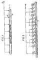
- Figure 3 illustrates an unsatisfactory method for reducing plug length. Air from supply 11 is injected continuously along the length of the conveying pipe 13 through injection points 12. This results in the aeration of the plug or the reduction of its plug length. However, this method requires high volumes of air to be employed and the plug velocity increaases as each injection point is passed because of the increased air volume being added behind the plug or plugs.
- a pneumatic conveying pressure vessel 1 is connected to a material receiving hopper 2 by a conveying pipe 3.
- a material feed hopper 5 is located above pressure vessel 1 and material may enter the latter from hopper 5 through inlet valve 4. Compressed air is applied to pressure vessel 1 via valve 6. Air can be allowed to escape from hopper 2 via filter 7.
- a series of valves 8 are located at spaced-apart positions along the pipeline. Valves 8 may be supplied with air at a higher pressure than that supplied to vessel 1. Valves 8 are set to open when a predetermined pressure is detected by means of sensing points 9. A sensing point 9 also operates a valve 10 which cancels the signal to valve 8 on the upstream side (nearer vessel 1), thus ensuring that the only valve 8 that operates is the one immediately ahead of the last sensing point to operate.
- Valves 8 will be set to operate only when the pressure at sensing point 9 is higher than the normal expected conveying pressure, the higher pressure indicating that a blockage has occurred.
- Figure 5 illustrates a section of the conveying pipe when a blockage occurs.
- the distance between valves 8 is such that the length of plug between valves 8 is less than for the critical d/L, ratio required to block the pipe.
- Sensing points S3, S4 and S5 will sense a pressure build up P1 when the blockage occurs, these sensing points will operate simultaneously.
- the pressure sensing means and air injection means can be of many different types, for example, electrical pressure transducers or pneumatic pressure switches for sensing, and air or electrically operated air valves.
- sensing points have been shown between the valves 8 being operated and the valves 8 being cancelled, it is possible to move the sensing point to a position upstream of the valves 8 being cancelled.
- An alternative arrangement is to provide only one sensing point for every 2 or 3 air injection points so that a group of valves will work simultaneously, the sensing point could be within the group or outside the group in relationship along the length of the pipe.
- the unblocking apparatus in accordance with the present invention may be used as an integral part of the conveying system.
- particulate material can be loaded into the conveying pipe in such a manner to ensure that it blocks in the conveying pipe.
- the unblocking apparatus will then convey the material along the conveying pipe in a relatively slow and orderly fashion until the end of the pipe is reached. It is particularly desirable for materials that are fragile or forwhich minimum degradation is required.
Landscapes
- Engineering & Computer Science (AREA)
- Mechanical Engineering (AREA)
- Air Transport Of Granular Materials (AREA)
Description
- The specification of this invention relates to conveying apparatus and in particular to apparatus for conveying particulate material.
- Many materials handled in dense or medium phase conveying systems are prone to pipe blockages for a variety of reasons; some of which are:-
- a) unstable material with varying particular size and/or moisture content;
- b) high friction relationship between material and pipe;
- c) failure of air supply or control system;
- d) plug length to diameter ratio incorrect;
- e) incorrect phase density or velocity in dilute or fluidised systems.
- When a blockage occurs it takes considerable time to unblock the pipe which normally requires dismantling.
- Some systems have been proposed which include means to prevent the occurrence of blockages. Two such systems are described in German patent specification No. 2219199 and 2919696. These use a pressure profile method of equating the pressure levels in the conduit to pressure levels to be expected in normal transport. In some cases it is important to transport material in a dense blocked form and these systems cannot operate in this way. Also in many cases air is supplied into the conduit at many places where there is no blockage. Although the systems are designed to prevent occurrence of blockages they are ineffective for unblocking a system.
- According to the present invention there is provided a method of unblocking conveying pipes for particulate material, comprising, detecting pressure increases above a predetermined limit at a plurality of positions along the pipe, feeding air into the pipe at positions which are spaced apart by a distance less than the critical particulate material plug length to conveying pipe diameter ratio that will result in a pipe blockage that cannot be moved by application of pressure applied at one end of the particulate material plug, the air injection occurring in accordance with the pressure detected in the pipe, such that the particulate material blockage may be reduced into lengths such that the critical ratio is not reached and such that air is only injected into the pipe in the region of a blockage.
- The method includes detecting a pressure increase above a predetermined limit at a plurality of appropriate positions along the pipe and operate so as to enable the reduction of the length of particulate material blockage into lengths such that the critical ratio is not reached.
- The present invention also provides apparatus for unblocking a conveying pipe for particulate material, characterised in that the apparatus comprises means for injecting air into the pipe located at positions along the pipe, which are spaced apart by a distance less than the critical particulate material plug length to conveying pipe diameter ratio (d/L) that will result in a pipe blockage that cannot be moved by application of pressure on the end of the particulate material plug, and, a plurality of pressure sensing means for detecting a pressure increase in the pipe above a predetermined level located at spaced apart positions along the conveying pipe, each air injection means being coupled to at least one sensing means and operating in accordance with the pressure detected at the or each sensing means coupled thereto, such that the air injection means operate to ensure the reduction of the length of the particulate material blockage into lengths such that the critical ration (d/L) is not reached and such that, each air injection means is only operated when a particulate material blockage is located in the pipe in the region of the air injection means.
- Preferably the sensing means are of a type that can detect the presence of a dense particulate material plug.
- In another preferred embodiment of the present invention the sensing means are of a type that can detect movement or non-movement of the particulate material plug.
- The apparatus and method of the present invention may relate to any conveying system for particulate material, for instance, a pneumatic conveying system or a hydraulic system. In the latter case the fluid for conveying an injection may be water.
- The arrangement may be such that a single sensing means may be linked to more than one injection device.
- The present invention also provides a conveying system, for instance, a pneumatic or hydraulic conveying system, for conveying particulate material along a conveying pipe, the system including apparatus of the invention for unblocking the conveying pipe.
- Apparatus and a method in accordance with the present invention will now be described, by way of example only, and with reference to the accompanying drawings:-
- Figure 1 shows the normal operation condition of a dense or medium phase conveying system under stable conditions. The diameter of the pipe is <l>d. The frictional resistance of the plug in the pipe is dependent on its length L and the difference between the pressures P1 and P2 on either side of the plug. The plug will move as long as the force on the end of the plug caused by the difference between P1 and P2 is greater than the frictional resistance of the plug.
- Figure 2 shows a pipe which is blocked. The plug length L is such that the frictional resistance due to natural pressure PS caused by material compaction is greater than the force on the end of the plug.
- In apparatus in accordance with the present invention the position where the blockage has occurred is detected and air is injected along the length of the blockage, reducing the plug length and allowing normal conveying to be resumed.
- Figure 3 illustrates an unsatisfactory method for reducing plug length. Air from supply 11 is injected continuously along the length of the conveying
pipe 13 throughinjection points 12. This results in the aeration of the plug or the reduction of its plug length. However, this method requires high volumes of air to be employed and the plug velocity increaases as each injection point is passed because of the increased air volume being added behind the plug or plugs. - Apparatus in accordance with the present invention is illustrated in Figure 4. A pneumatic conveying pressure vessel 1 is connected to a material receiving
hopper 2 by a conveying pipe 3. Amaterial feed hopper 5 is located above pressure vessel 1 and material may enter the latter fromhopper 5 through inlet valve 4. Compressed air is applied to pressure vessel 1 viavalve 6. Air can be allowed to escape fromhopper 2 viafilter 7. - A series of
valves 8 are located at spaced-apart positions along the pipeline.Valves 8 may be supplied with air at a higher pressure than that supplied to vessel 1.Valves 8 are set to open when a predetermined pressure is detected by means of sensing points 9. A sensing point 9 also operates avalve 10 which cancels the signal tovalve 8 on the upstream side (nearer vessel 1), thus ensuring that theonly valve 8 that operates is the one immediately ahead of the last sensing point to operate. - Valves 8 will be set to operate only when the pressure at sensing point 9 is higher than the normal expected conveying pressure, the higher pressure indicating that a blockage has occurred.
- Figure 5 illustrates a section of the conveying pipe when a blockage occurs. The distance between
valves 8 is such that the length of plug betweenvalves 8 is less than for the critical d/L, ratio required to block the pipe. Sensing points S3, S4 and S5 will sense a pressure build up P1 when the blockage occurs, these sensing points will operate simultaneously. - S5 will try to open V5 but S4 will cancel this signal via C5. S4 will try to open V4 but S3 will cancel this signal via C4. S3 will open V3 injecting air into the blockage. If the blockage is not reduced in length sufficiently to move, the pressure build-up near V3 will operate S2 cancelling out V3 via C3 and operating V2 and so on until the blockage has been reduced into several discrete plugs of reduced length that will move. When conveying has resumed the pressure P1 will reduce and fall belowthe point at which the sensing points will operate. In practice, the operation of the sensing points and clearing of the pipe takes only a few seconds.
- The pressure sensing means and air injection means can be of many different types, for example, electrical pressure transducers or pneumatic pressure switches for sensing, and air or electrically operated air valves.
- Although the sensing points have been shown between the
valves 8 being operated and thevalves 8 being cancelled, it is possible to move the sensing point to a position upstream of thevalves 8 being cancelled. An alternative arrangement is to provide only one sensing point for every 2 or 3 air injection points so that a group of valves will work simultaneously, the sensing point could be within the group or outside the group in relationship along the length of the pipe. - The unblocking apparatus in accordance with the present invention may be used as an integral part of the conveying system. Thus particulate material can be loaded into the conveying pipe in such a manner to ensure that it blocks in the conveying pipe. The unblocking apparatus will then convey the material along the conveying pipe in a relatively slow and orderly fashion until the end of the pipe is reached. It is particularly desirable for materials that are fragile or forwhich minimum degradation is required.
Claims (7)
Applications Claiming Priority (2)
| Application Number | Priority Date | Filing Date | Title |
|---|---|---|---|
| GB8107284 | 1981-03-09 | ||
| GB8107284 | 1981-03-09 |
Publications (2)
| Publication Number | Publication Date |
|---|---|
| EP0060135A1 EP0060135A1 (en) | 1982-09-15 |
| EP0060135B1 true EP0060135B1 (en) | 1985-09-11 |
Family
ID=10520238
Family Applications (1)
| Application Number | Title | Priority Date | Filing Date |
|---|---|---|---|
| EP82301194A Expired EP0060135B1 (en) | 1981-03-09 | 1982-03-09 | Conveying apparatus |
Country Status (4)
| Country | Link |
|---|---|
| US (1) | US4515503A (en) |
| EP (1) | EP0060135B1 (en) |
| DE (1) | DE3266106D1 (en) |
| WO (1) | WO1982003066A1 (en) |
Cited By (1)
| Publication number | Priority date | Publication date | Assignee | Title |
|---|---|---|---|---|
| US20220219918A1 (en) * | 2019-05-03 | 2022-07-14 | Schenck Process Europe Gmbh | Material conveying apparatus with shut down valves |
Families Citing this family (36)
| Publication number | Priority date | Publication date | Assignee | Title |
|---|---|---|---|---|
| DE3435907A1 (en) * | 1984-09-29 | 1986-04-10 | AVT Anlagen- und Verfahrenstechnik GmbH, 7981 Vogt | METHOD AND DEVICE FOR THE PNEUMATIC AND HYDRAULIC TRANSPORT OF SOLIDS BY PIPING |
| DE3714924A1 (en) * | 1987-05-05 | 1988-12-01 | Waeschle Maschf Gmbh | DEVICE FOR PNEUMATICALLY CONVEYING SCHUETTGUT |
| DE3714923A1 (en) * | 1987-05-05 | 1988-12-01 | Waeschle Maschf Gmbh | DEVICE FOR PNEUMATICALLY CONVEYING SCHUETTGUT |
| US4792235A (en) * | 1987-09-21 | 1988-12-20 | Fuller Company | Gaseous fluid supply system for a vessel |
| EP0379628B1 (en) * | 1989-01-27 | 1994-08-17 | Alb. Klein GmbH & Co. KG | Method for the pneumatic transport of materials and device for the air-feed control thereof |
| US4938637A (en) * | 1989-06-09 | 1990-07-03 | Lybecker G Wayne | Method and apparatus for bottom loading a pneumatic transport pressure vessel |
| FR2671061A1 (en) * | 1990-12-26 | 1992-07-03 | Pechiney Aluminium | DEVICE FOR SEPARATING FLUIDIZED BED MATERIAL AND COLDING DETECTION. |
| US5558472A (en) * | 1993-10-07 | 1996-09-24 | Sumitomo Chemical Company, Limited | Method and apparatus for transporting particles |
| US5584612A (en) * | 1994-11-02 | 1996-12-17 | Nol-Tec Systems, Inc. | Apparatus and process for pneumatically conveying material and for controlling the feed of supplemental gas |
| DE19518013A1 (en) * | 1995-05-17 | 1996-11-21 | Mann & Hummel Filter | Feed device for granular or powdered loose material in plastics mfg. plant |
| DE19518012A1 (en) * | 1995-05-17 | 1996-11-21 | Mann & Hummel Filter | Feed device for granular or powdered loose material in plastics mfg. plant |
| US5813801A (en) * | 1996-06-28 | 1998-09-29 | Mac Equipment, Inc. | Dense phase particulate conveying system and method with continuous air leakage management |
| US5855456A (en) * | 1996-10-16 | 1999-01-05 | Ultraflo Corporation | Apparatus and method for unblocking conveying pipe |
| US6000884A (en) * | 1997-03-27 | 1999-12-14 | Advanced Manufacturing Technology | Apparatus for controlling flow in air conveyor systems |
| US6106202A (en) * | 1998-05-04 | 2000-08-22 | Nol-Tec Systems, Inc. | Pneumatic conveying air assist line with air bleed |
| GB9913909D0 (en) * | 1999-06-16 | 1999-08-18 | Clyde Pneumatic Conveying Limi | Pneumatic conveying |
| GB0121353D0 (en) * | 2001-09-04 | 2001-10-24 | Rig Technology Ltd | Improvements in or relating to transport of waste materials |
| US6764253B1 (en) * | 2003-02-14 | 2004-07-20 | The Young Industries, Inc. | System and method for assuring fluidization of a material transported in a pneumatic conveying system |
| US6936092B2 (en) * | 2003-03-19 | 2005-08-30 | Varco I/P, Inc. | Positive pressure drilled cuttings movement systems and methods |
| US7493969B2 (en) * | 2003-03-19 | 2009-02-24 | Varco I/P, Inc. | Drill cuttings conveyance systems and methods |
| GB2423781B (en) * | 2003-03-19 | 2007-03-28 | Varco Int | Apparatus and method for moving drilled cuttings |
| US20080128173A1 (en) * | 2006-04-05 | 2008-06-05 | Baker Hughes Incorporated | Drill Cuttings Transfer System and Related Methods |
| US9725246B2 (en) | 2008-05-20 | 2017-08-08 | Flexibility Engineering, Llc | Flow restricted positioner control apparatus and methods |
| US9133865B2 (en) | 2008-05-20 | 2015-09-15 | Flexibility Engineering, Llc | Position control apparatus |
| DE102008063505A1 (en) * | 2008-12-17 | 2010-07-01 | Uhde Gmbh | Process for equalizing the production of fuels in a gasifier for the production of synthesis gas |
| FR2952363B1 (en) * | 2009-11-09 | 2011-11-11 | Alcan Int Ltd | POTENTIALLY FLUIDIZING DEVICE FOR CONVEYING PULVERULENT MATERIALS IN HYPERDENSE BED |
| NL1039764C2 (en) * | 2012-08-17 | 2014-02-18 | J O A Technology Beheer B V | A method of, a control system, a device, a sensor and a computer program product for controlling transport of fibrous material in a transport line of a pneumatic conveying system. |
| BR112016007441A2 (en) * | 2013-10-03 | 2019-12-17 | M I Drilling Fluids Uk Ltd | elongated appliance, appliance, and method |
| DE102014016109A1 (en) * | 2014-10-30 | 2016-05-04 | Eisenmann Se | Recovery system |
| EP3271272A4 (en) * | 2015-03-19 | 2018-12-05 | IPEG, Inc. | Material delivery system |
| US9677576B2 (en) | 2015-09-14 | 2017-06-13 | Flexbility Engineering, LLC | Flow restricted positioner control apparatus and methods |
| GB201611662D0 (en) | 2016-07-04 | 2016-08-17 | Clyde Process Ltd | Material conveying apparatus and method |
| US10421625B2 (en) * | 2017-09-08 | 2019-09-24 | Cnh Industrial Canada, Ltd. | System and method for removing blockages present in a delivery conduit of a seeder |
| DE102018106228A1 (en) * | 2018-03-16 | 2019-09-19 | Seepex Gmbh | Plant for conveying pasty material |
| US11613950B2 (en) * | 2019-10-24 | 2023-03-28 | Halliburton Energy Services, Inc. | Core sampling and analysis using a sealed pressure vessel |
| BR112022024009A2 (en) * | 2020-05-25 | 2022-12-20 | Nte Holding S R L | FLUID CONTROL SYSTEM IN PNEUMATIC TRANSPORT PIPELINES FOR POWDER OR GRANULATED MATERIAL |
Citations (2)
| Publication number | Priority date | Publication date | Assignee | Title |
|---|---|---|---|---|
| DE2219199A1 (en) | 1972-04-20 | 1973-10-25 | Hartmann Ag Maschf | DEVICE FOR THE AUTOMATICALLY CONTROLLED ADDITION OF CONVEYING MEDIUM IN A PIPELINE FOR PNEUMATIC PLUG TRANSFER |
| DE2919696A1 (en) | 1978-08-08 | 1980-02-14 | Takraf Schwermasch | Abrasive material pneumatic conveyor - has pressure-controlled valves between branches from pipe parallel to conveyor tube |
Family Cites Families (4)
| Publication number | Priority date | Publication date | Assignee | Title |
|---|---|---|---|---|
| DE2305030C3 (en) * | 1973-02-02 | 1983-02-10 | Wäschle Maschinenfabrik GmbH, 7980 Ravensburg | System for the pneumatic conveying of bulk goods |
| SU698870A1 (en) * | 1977-01-17 | 1979-11-25 | Всесоюзный Научно-Исследовательский И Проектно-Конструкторский Угольный Институт | Apparatus for pressure-head conveying of loose materials through pipeline |
| SU676513A1 (en) * | 1977-05-03 | 1979-07-30 | Научно-Исследовательский Институт Прикладной Математики И Механики При Томском Ордена Трудового Красного Знамени Государственном Университете Им. В.В.Куйбышева | Unit for pneumatic conveying of loose materials |
| DE3037517C2 (en) * | 1980-10-03 | 1983-12-08 | Waeschle Maschinenfabrik Gmbh, 7980 Ravensburg | System for the pneumatic conveying of bulk goods |
-
1982
- 1982-03-09 US US06/441,517 patent/US4515503A/en not_active Expired - Lifetime
- 1982-03-09 EP EP82301194A patent/EP0060135B1/en not_active Expired
- 1982-03-09 DE DE8282301194T patent/DE3266106D1/en not_active Expired
- 1982-03-09 WO PCT/GB1982/000078 patent/WO1982003066A1/en not_active Ceased
Patent Citations (2)
| Publication number | Priority date | Publication date | Assignee | Title |
|---|---|---|---|---|
| DE2219199A1 (en) | 1972-04-20 | 1973-10-25 | Hartmann Ag Maschf | DEVICE FOR THE AUTOMATICALLY CONTROLLED ADDITION OF CONVEYING MEDIUM IN A PIPELINE FOR PNEUMATIC PLUG TRANSFER |
| DE2919696A1 (en) | 1978-08-08 | 1980-02-14 | Takraf Schwermasch | Abrasive material pneumatic conveyor - has pressure-controlled valves between branches from pipe parallel to conveyor tube |
Non-Patent Citations (2)
| Title |
|---|
| PNEUMOTRANSPORT FIFTH INTERNATIONAL CONFERENCE ON THE PNEUMATIC TRANSPORT OF SOLIDS IN PIPES, 16 April 1980 (1980-04-16) |
| VT'' VERFAHRENSTECHNIK, vol. 4, April 1978 (1978-04-01), pages 190 - 202 |
Cited By (2)
| Publication number | Priority date | Publication date | Assignee | Title |
|---|---|---|---|---|
| US20220219918A1 (en) * | 2019-05-03 | 2022-07-14 | Schenck Process Europe Gmbh | Material conveying apparatus with shut down valves |
| US11760583B2 (en) * | 2019-05-03 | 2023-09-19 | Schenck Process Europe Gmbh | Material conveying apparatus with shut down valves |
Also Published As
| Publication number | Publication date |
|---|---|
| US4515503A (en) | 1985-05-07 |
| EP0060135A1 (en) | 1982-09-15 |
| DE3266106D1 (en) | 1985-10-17 |
| WO1982003066A1 (en) | 1982-09-16 |
Similar Documents
| Publication | Publication Date | Title |
|---|---|---|
| EP0060135B1 (en) | Conveying apparatus | |
| US4909676A (en) | Apparatus for pneumatically conveying bulk material | |
| EP3478611B1 (en) | Material conveying apparatus and method | |
| US5407305A (en) | Continuous dense phase conveying method utilizing high pressure gas at predetermined gas pressures within a conveying pipe | |
| US4715748A (en) | Process and equipment for pneumatic and hydraulic transport of bulk materials through pipes | |
| EP0988243B1 (en) | A method and a device for transporting bulk material, granular material or powdery material | |
| CN113784904B (en) | Material handling equipment with shut-off valves | |
| GB1454114A (en) | Method and apparatus for the pneumatic conveying of bulk material | |
| US4220426A (en) | Tubular pneumatic conveyor pipeline | |
| US4067622A (en) | Method and apparatus for the pneumatic conveying of bulk material | |
| US5855456A (en) | Apparatus and method for unblocking conveying pipe | |
| CA1180737A (en) | Method of unplugging dense phase conveying system | |
| GB2392895A (en) | Pneumatic conveyor control system | |
| JPH06255778A (en) | Pneumatic conveying device for bulk goods | |
| KR850000641A (en) | Distribution system of particles in gas | |
| US4715749A (en) | Pneumatic transport conveyor | |
| CA2185885A1 (en) | Pneumatic bulk material slug transport process and device with attenuated shocks | |
| US5259123A (en) | Aeration rod-out assembly | |
| JPH06191640A (en) | Low speed high density transport device | |
| JPS6331939A (en) | High-pressure carrier device for powder or grain substance | |
| EP0479864B1 (en) | Buffer volume | |
| JPH01127523A (en) | Conveying device by low-speed and high-density air for bulk material | |
| CN223133490U (en) | Pipeline anti-blocking device of positive pressure dense-phase conveying system | |
| KR100426177B1 (en) | Powder sample transfer pipe for floating powder sample | |
| SU1518255A1 (en) | Device for separating loose material from gas flow in pneumatic transport system |
Legal Events
| Date | Code | Title | Description |
|---|---|---|---|
| PUAI | Public reference made under article 153(3) epc to a published international application that has entered the european phase |
Free format text: ORIGINAL CODE: 0009012 |
|
| AK | Designated contracting states |
Designated state(s): DE FR GB IT SE |
|
| 17P | Request for examination filed |
Effective date: 19830309 |
|
| GRAA | (expected) grant |
Free format text: ORIGINAL CODE: 0009210 |
|
| AK | Designated contracting states |
Designated state(s): DE FR GB IT SE |
|
| PG25 | Lapsed in a contracting state [announced via postgrant information from national office to epo] |
Ref country code: IT Free format text: LAPSE BECAUSE OF FAILURE TO SUBMIT A TRANSLATION OF THE DESCRIPTION OR TO PAY THE FEE WITHIN THE PRESCRIBED TIME-LIMIT;WARNING: LAPSES OF ITALIAN PATENTS WITH EFFECTIVE DATE BEFORE 2007 MAY HAVE OCCURRED AT ANY TIME BEFORE 2007. THE CORRECT EFFECTIVE DATE MAY BE DIFFERENT FROM THE ONE RECORDED. Effective date: 19850911 |
|
| PG25 | Lapsed in a contracting state [announced via postgrant information from national office to epo] |
Ref country code: SE Effective date: 19850930 |
|
| REF | Corresponds to: |
Ref document number: 3266106 Country of ref document: DE Date of ref document: 19851017 |
|
| ET | Fr: translation filed | ||
| PLBI | Opposition filed |
Free format text: ORIGINAL CODE: 0009260 |
|
| 26 | Opposition filed |
Opponent name: AVT ANLAGEN- UND VERFAHRENSTECHNIK GMBH Effective date: 19860610 Opponent name: BUEHLER - MIAG GMBH Effective date: 19860609 |
|
| PG25 | Lapsed in a contracting state [announced via postgrant information from national office to epo] |
Ref country code: GB Effective date: 19870309 |
|
| GBPC | Gb: european patent ceased through non-payment of renewal fee | ||
| PG25 | Lapsed in a contracting state [announced via postgrant information from national office to epo] |
Ref country code: FR Free format text: LAPSE BECAUSE OF NON-PAYMENT OF DUE FEES Effective date: 19871130 |
|
| PG25 | Lapsed in a contracting state [announced via postgrant information from national office to epo] |
Ref country code: DE Effective date: 19871201 |
|
| REG | Reference to a national code |
Ref country code: FR Ref legal event code: ST |
|
| RDAG | Patent revoked |
Free format text: ORIGINAL CODE: 0009271 |
|
| STAA | Information on the status of an ep patent application or granted ep patent |
Free format text: STATUS: PATENT REVOKED |
|
| 27W | Patent revoked |
Effective date: 19871226 |
|
| GBPR | Gb: patent revoked under art. 102 of the ep convention designating the uk as contracting state | ||
| REG | Reference to a national code |
Ref country code: GB Ref legal event code: 7102 |
|
| PLAB | Opposition data, opponent's data or that of the opponent's representative modified |
Free format text: ORIGINAL CODE: 0009299OPPO |