EP0059726B1 - Water purity measurement - Google Patents
Water purity measurement Download PDFInfo
- Publication number
- EP0059726B1 EP0059726B1 EP81902465A EP81902465A EP0059726B1 EP 0059726 B1 EP0059726 B1 EP 0059726B1 EP 81902465 A EP81902465 A EP 81902465A EP 81902465 A EP81902465 A EP 81902465A EP 0059726 B1 EP0059726 B1 EP 0059726B1
- Authority
- EP
- European Patent Office
- Prior art keywords
- pipe
- water
- electrodes
- voltmeter
- cell
- Prior art date
- Legal status (The legal status is an assumption and is not a legal conclusion. Google has not performed a legal analysis and makes no representation as to the accuracy of the status listed.)
- Expired
Links
- XLYOFNOQVPJJNP-UHFFFAOYSA-N water Substances O XLYOFNOQVPJJNP-UHFFFAOYSA-N 0.000 title claims abstract description 59
- 238000005259 measurement Methods 0.000 title description 6
- 238000000034 method Methods 0.000 claims abstract description 12
- 239000011810 insulating material Substances 0.000 claims description 19
- 230000000694 effects Effects 0.000 claims description 11
- 238000011156 evaluation Methods 0.000 claims description 3
- 239000012777 electrically insulating material Substances 0.000 claims description 2
- 239000000463 material Substances 0.000 description 12
- 239000004065 semiconductor Substances 0.000 description 5
- 229920003023 plastic Polymers 0.000 description 4
- 239000004033 plastic Substances 0.000 description 4
- 239000000126 substance Substances 0.000 description 4
- 238000010276 construction Methods 0.000 description 2
- 239000000356 contaminant Substances 0.000 description 2
- 238000005516 engineering process Methods 0.000 description 2
- 238000012360 testing method Methods 0.000 description 2
- 229920004943 Delrin® Polymers 0.000 description 1
- 229920005439 Perspex® Polymers 0.000 description 1
- XUIMIQQOPSSXEZ-UHFFFAOYSA-N Silicon Chemical compound [Si] XUIMIQQOPSSXEZ-UHFFFAOYSA-N 0.000 description 1
- 238000013459 approach Methods 0.000 description 1
- 239000007864 aqueous solution Substances 0.000 description 1
- 238000001311 chemical methods and process Methods 0.000 description 1
- 238000011109 contamination Methods 0.000 description 1
- 239000012153 distilled water Substances 0.000 description 1
- 239000012535 impurity Substances 0.000 description 1
- 238000009413 insulation Methods 0.000 description 1
- 230000002427 irreversible effect Effects 0.000 description 1
- 239000007788 liquid Substances 0.000 description 1
- 238000012986 modification Methods 0.000 description 1
- 230000004048 modification Effects 0.000 description 1
- 238000012544 monitoring process Methods 0.000 description 1
- 239000004926 polymethyl methacrylate Substances 0.000 description 1
- 238000012545 processing Methods 0.000 description 1
- 238000005086 pumping Methods 0.000 description 1
- 238000011160 research Methods 0.000 description 1
- 229910052710 silicon Inorganic materials 0.000 description 1
- 239000010703 silicon Substances 0.000 description 1
- 239000007787 solid Substances 0.000 description 1
- 239000002904 solvent Substances 0.000 description 1
- 239000008399 tap water Substances 0.000 description 1
- 235000020679 tap water Nutrition 0.000 description 1
- 235000012431 wafers Nutrition 0.000 description 1
Images


Classifications
-
- G—PHYSICS
- G01—MEASURING; TESTING
- G01N—INVESTIGATING OR ANALYSING MATERIALS BY DETERMINING THEIR CHEMICAL OR PHYSICAL PROPERTIES
- G01N27/00—Investigating or analysing materials by the use of electric, electrochemical, or magnetic means
- G01N27/60—Investigating or analysing materials by the use of electric, electrochemical, or magnetic means by investigating electrostatic variables, e.g. electrographic flaw testing
-
- G—PHYSICS
- G01—MEASURING; TESTING
- G01N—INVESTIGATING OR ANALYSING MATERIALS BY DETERMINING THEIR CHEMICAL OR PHYSICAL PROPERTIES
- G01N33/00—Investigating or analysing materials by specific methods not covered by groups G01N1/00 - G01N31/00
- G01N33/18—Water
Definitions
- This invention relates to the measurement of water purity, particularly where the purity is required to be measured in fractions of a part per million.
- the normal technique used to assess the purity of water is to measure the concentration of the contaminants in their ionised state using standard conductivity methods. This method, while being most satisfactory at normal impurity levels such as in tap water, distilled water, and the like, becomes extremely difficult when the water approaches the ultimate in chemical purity with resistivities of 10's of MQcm, the level required in the semiconductor industry.
- US-A-3 502 965 discloses a method for measuring the charge condition in a sample stream of contaminated water.
- the water flows through a cell comprising a pipe of insulating material disposed between electrodes arranged to measure the electromotive force developed by the water flowing through the cell.
- GB-A-2 034 902 discloses a system for monitoring a low conductivity liquid carrying an electrostatic charge (due to the tribo-electric effect) and flowing along a pipeline, comprising two separately insulated conductive wall sections of the pipeline.
- a method for measuring the purity of water which comprises causing the water to flow through a cell comprising a single pipe section of insulating material disposed between electrodes arranged to measure the electromotive force generated by the water flowing through the cell by connecting to the said electrodes a voltmeter of sufficiently high input resistance as to be ignored, characterised by calculating the resistivity p of the water from the tribo-electric electromotive force generated, the value of the resistivity p being indicative of the level of purity of the water, by connecting across the voltmeter a pair of alternately selectable parallel different value resistances R m1 and R m2' and by determining the resistivity p of the water by the formula wherein d is the internal diameter of the single pipe section, I is its length, and V 1 and V 2 are the tribo-electric voltages detected by the voltmeter when the resistances R m1 and R m2 respectively are switched in parallel with the voltmeter.
- a device for measuring the purity of water which comprises a cell having a pipe in it arranged for water to be measured to flow therethrough, said pipe being formed of electrically insulating material, an electrode at each end of the said pipe, and measuring means including a voltmeter connected to said electrodes having a sufficiently high input resistance as to be ignored, characterised by a pair of alternately selectable parallel different value resistances connected across the voltmeter, to enable said voltmeter to detect the two corresponding tribo-electric voltages V" V 2 necessary for the evaluation of the formula used in connection with the aforementioned first aspect of the present invention.
- the invention may be modified by having electrodes arranged to provide differing characteristics from adjacent sections of the cell so formed. This can be achieved by using materials of different characteristic or by having differing diameters in the cell to give a different velocity and hence achieve a different tribo-electric e.m.f.
- a method for measuring the purity of water which comprises causing the water to flow through a cell in the form of a pipe of insulating material disposed between electrodes arranged to measure the electromotive force generated by the water flowing through the cell by connecting to the said electrodes a voltmeter of sufficiently high input resistance as to be ignored, characterised in that the pipe comprises two pipe sections with the same internal diameter and of insulating material having different characteristics producing different partial cell voltages by the tribo-electric effect, the pipe having an intermediate electrode between the two pipe sections, the level of purity of the water being indicated by the value of the resistivity p thereof, the resistivity p being found by interconnecting the end electrodes electrically and connecting said voltmeter to the intermediate electrode on the one hand and the end electrodes on the other hand, and across it a pair of alternately selectable parallel different value resistances R m1 and R m2 , and determining the resistivity p of the water by the formula wherein d 2 and 1 2 are the
- a method for measuring the purity of water which comprises causing the water to flow through a cell in the form of a pipe of insulating material disposed between electrodes arranged to measure the electromotive force generated by the water flowing through the cell, by connecting to the said electrodes a voltmeter of sufficiently high input resistance as to be ignored, characterised in that the pipe comprises two pipe sections of the same insulating material, and with different internal diameters producing different partial cell voltages by the tribo-electric effect, the pipe having an intermediate electrode between the two pipe sections, the level of purity of the water being indicated by the value of the resistivity p thereof, which is found by interconnecting the end electrodes electrically and connecting said voltmeter to the intermediate electrode on the one hand and the end electrodes on the other hand, and across it a pair of alternately selectable parallel different value resistances R m1 and R m2 , and determining the resistivity p of the water by the formula wherein d 2 and I 2 are the internal diameter and
- Embodiments of the device according to the aforementioned second aspect of the present invention enable the evaluation of the formulas used in connection with the aforementioned third or fourth aspect of the present invention.
- two dissimilar cell sections are preferably used which vary by wall material characteristic, such as by using for instance a material known under the trade mark "Delrin” for one section of the cell and material known under the trade mark “Perspex” for the other section of the cell, arranged coextensive the one with the other with an end electrode at each end of the cell so formed and an intermediate electrode between the two sections.
- the two sections can be of similar material but vary from each other by the internal diameter of the pipe sections.
- Fig. 1 shows a pipe section 1 of insulating material having electrodes 2 and 3 at the ends, the pipe section 1 being connected between pipes 4 and 5 through which the water flow occurs.
- this can be constructed by threading the two ends of the plastic pipe section 1 and screwing to it a pair of electrodes 2 and 3 into which the ends of the pipes 4 and 5 project. Wedge nuts 6 and 7 lock the pipes 4 and 5 in position and effect a seal.
- the device of Fig. 2 has two pipe sections 10 and 11 of insulating material, which differ in their physical characteristic, using three electrodes 12, 13 and 14. Electrodes 12 and 14 respectively joined to the ends of the pipes 15 and 16 are connected externally by an electrical short circuit. Readings are taken between electrodes 13 and either electrode 12 or electrode 14.
- the actual construction of this can again be similar to the form illustrated in Fig. 4 excepting that an intermediate electrode would be used, screwing into both of the pipe sections 10 and 11 of different insulating material.
- the form illustrated in Fig. 3 uses pipe sections 20 and 21 of different internal diameters with electrodes 22, 23 and 24. All this is fitted between the ends of the pipes 25 and 26, and could be similar to the form illustrated in Fig. 5, in which two end electrodes 22 and 24 are joined by an external sleeve 27 in which the pipe sections 20 and 21 of similar insulating material are disposed with the intermediate electrode 23 between them.
- the end electrodes 22 and 24 again have sockets to take the ends of the pipes 25 and 26 which are locked to the electrodes 22 and 24 by wedge nuts 28 and 29 which screw on to the electrodes 22 and 24. Insulation 30 isolates the intermediate electrode 23 from the sleeve 27.
- the method of calculating the water purity is as follows:
- R may then be derived from the following relation: If dissimilar plastics are used for the pipes or if the flow rates are modified in certain areas of the pipe by changing the diameter, then once again the e.m.f. can be measured.
- Cells having an optimum of output voltage for a given system may be designed.
- a cell can be tailored by choice of cell length, diameter, and insulating materials.
Landscapes
- Chemical & Material Sciences (AREA)
- Health & Medical Sciences (AREA)
- Life Sciences & Earth Sciences (AREA)
- General Health & Medical Sciences (AREA)
- Immunology (AREA)
- Pathology (AREA)
- Analytical Chemistry (AREA)
- Biochemistry (AREA)
- Physics & Mathematics (AREA)
- General Physics & Mathematics (AREA)
- Chemical Kinetics & Catalysis (AREA)
- Electrochemistry (AREA)
- Engineering & Computer Science (AREA)
- Food Science & Technology (AREA)
- Medicinal Chemistry (AREA)
- Investigating Or Analyzing Materials By The Use Of Electric Means (AREA)
- Other Investigation Or Analysis Of Materials By Electrical Means (AREA)
Abstract
Description
- This invention relates to the measurement of water purity, particularly where the purity is required to be measured in fractions of a part per million.
- With the enormous expansion of activity in Semiconductor Technology over the last decade or so, has come the need for chemicals of hitherto unheard of purity. We see reference to materials which typically have purity levels measured in fractions of a part per million being used routinely in wet-way chemical processes on silicon wafers. These materials are used in aqueous solutions, which in turn places a very considerable emphasis on the purity of the solvent, water. The presence of traces of inorganic contaminants in both the chemicals being used and in the water can lead to irreversible modification of the semiconductor materials during processing.
- The normal technique used to assess the purity of water is to measure the concentration of the contaminants in their ionised state using standard conductivity methods. This method, while being most satisfactory at normal impurity levels such as in tap water, distilled water, and the like, becomes extremely difficult when the water approaches the ultimate in chemical purity with resistivities of 10's of MQcm, the level required in the semiconductor industry.
- US-A-3 502 965 discloses a method for measuring the charge condition in a sample stream of contaminated water. The water flows through a cell comprising a pipe of insulating material disposed between electrodes arranged to measure the electromotive force developed by the water flowing through the cell.
- GB-A-2 034 902 discloses a system for monitoring a low conductivity liquid carrying an electrostatic charge (due to the tribo-electric effect) and flowing along a pipeline, comprising two separately insulated conductive wall sections of the pipeline.
- In the course of our research we have found that a tribo-electric e.m.f. which is generated due to friction in flowing water, particularly when it is transported through insulating plastic pipes, can be used to measure water purity. In fact, this e.m.f. can cause damage to highly reflecting surfaces in water cooled pumping cavities in a solid state laser. In this invention use is made of this tribo-electric effect to measure the resistivity of the water, an inverse function of the ionic contamination and hence its purity, in a very simple measuring cell.
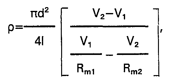
- According to a first aspect of the present invention there is provided a method for measuring the purity of water, which comprises causing the water to flow through a cell comprising a single pipe section of insulating material disposed between electrodes arranged to measure the electromotive force generated by the water flowing through the cell by connecting to the said electrodes a voltmeter of sufficiently high input resistance as to be ignored, characterised by calculating the resistivity p of the water from the tribo-electric electromotive force generated, the value of the resistivity p being indicative of the level of purity of the water, by connecting across the voltmeter a pair of alternately selectable parallel different value resistances Rm1 and Rm2' and by determining the resistivity p of the water by the formula

- According to a second aspect of the present invention there is provided a device for measuring the purity of water which comprises a cell having a pipe in it arranged for water to be measured to flow therethrough, said pipe being formed of electrically insulating material, an electrode at each end of the said pipe, and measuring means including a voltmeter connected to said electrodes having a sufficiently high input resistance as to be ignored, characterised by a pair of alternately selectable parallel different value resistances connected across the voltmeter, to enable said voltmeter to detect the two corresponding tribo-electric voltages V" V2 necessary for the evaluation of the formula used in connection with the aforementioned first aspect of the present invention.
- In specific applications, such as the semi- conductor technology referred to above, where generally the pipes are looped and the two ends are at the same potential, the invention may be modified by having electrodes arranged to provide differing characteristics from adjacent sections of the cell so formed. This can be achieved by using materials of different characteristic or by having differing diameters in the cell to give a different velocity and hence achieve a different tribo-electric e.m.f.
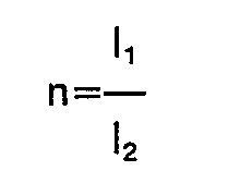
- According to a third aspect of the present invention there is provided a method for measuring the purity of water, which comprises causing the water to flow through a cell in the form of a pipe of insulating material disposed between electrodes arranged to measure the electromotive force generated by the water flowing through the cell by connecting to the said electrodes a voltmeter of sufficiently high input resistance as to be ignored, characterised in that the pipe comprises two pipe sections with the same internal diameter and of insulating material having different characteristics producing different partial cell voltages by the tribo-electric effect, the pipe having an intermediate electrode between the two pipe sections, the level of purity of the water being indicated by the value of the resistivity p thereof, the resistivity p being found by interconnecting the end electrodes electrically and connecting said voltmeter to the intermediate electrode on the one hand and the end electrodes on the other hand, and across it a pair of alternately selectable parallel different value resistances Rm1 and Rm2, and determining the resistivity p of the water by the formula


- According to a fourth aspect of the present invention there is provided a method for measuring the purity of water, which comprises causing the water to flow through a cell in the form of a pipe of insulating material disposed between electrodes arranged to measure the electromotive force generated by the water flowing through the cell, by connecting to the said electrodes a voltmeter of sufficiently high input resistance as to be ignored, characterised in that the pipe comprises two pipe sections of the same insulating material, and with different internal diameters producing different partial cell voltages by the tribo-electric effect, the pipe having an intermediate electrode between the two pipe sections, the level of purity of the water being indicated by the value of the resistivity p thereof, which is found by interconnecting the end electrodes electrically and connecting said voltmeter to the intermediate electrode on the one hand and the end electrodes on the other hand, and across it a pair of alternately selectable parallel different value resistances Rm1 and Rm2, and determining the resistivity p of the water by the formula


- Embodiments of the device according to the aforementioned second aspect of the present invention enable the evaluation of the formulas used in connection with the aforementioned third or fourth aspect of the present invention.
- While the invention has been based on the semi-conductor industry, application of this effect could be widespread in many chemical plants and other industries.
- In the case of where the two ends of the pipe are at a common potential, two dissimilar cell sections are preferably used which vary by wall material characteristic, such as by using for instance a material known under the trade mark "Delrin" for one section of the cell and material known under the trade mark "Perspex" for the other section of the cell, arranged coextensive the one with the other with an end electrode at each end of the cell so formed and an intermediate electrode between the two sections.
- Instead of using two sections of the cell of dissimilar material the two sections can be of similar material but vary from each other by the internal diameter of the pipe sections.
- For a better understanding of the invention and to show how it may be put into effect reference will now be made by way of example to the accompanying drawings in which:
- Fig. 1A is a schematic central section of a cell formed of a section of insulating material having an electrode at each end, B showing the equivalent electrical circuit, and C the measuring circuit;
- Fig. 2A is a similar view to Fig. 1A but showing the assembly used when the pipe is looped, in which case two insulating sections with electrodes at each end are used, B again showing the equivalent circuit, and C the measuring circuit of this type of cell;
- Fig. 3 is a further schematic view showing a cell with varying diameters as opposed to varying materials, the equivalent circuits being similar to B and C of Fig. 2;
- Fig. 4 is a central longitudinal section showing how the device of Fig. 1 can be constructed; and
- Fig. 5 is a view similar to Fig. 4 but showing construction of a cell as shown in Fig. 3.
- Fig. 1 shows a
pipe section 1 of insulatingmaterial having electrodes pipe section 1 being connected betweenpipes plastic pipe section 1 and screwing to it a pair ofelectrodes pipes pipes - The device of Fig. 2 has two
pipe sections 10 and 11 of insulating material, which differ in their physical characteristic, using threeelectrodes Electrodes pipes electrodes 13 and eitherelectrode 12 orelectrode 14. The actual construction of this can again be similar to the form illustrated in Fig. 4 excepting that an intermediate electrode would be used, screwing into both of thepipe sections 10 and 11 of different insulating material. - The form illustrated in Fig. 3 uses
pipe sections electrodes pipes end electrodes external sleeve 27 in which thepipe sections intermediate electrode 23 between them. Theend electrodes pipes electrodes wedge nuts electrodes Insulation 30 isolates theintermediate electrode 23 from thesleeve 27. - The method of calculating the water purity is as follows:
- Referring first to the simple cell of Fig. 1, the equivalent electrical circuit may be considered as shown in Fig. 1 B and the measuring circuit Fig. 1C where

- To obtain a value for R, the water resistance, two measurements are made using two resistors Rm1 and Rm2 giving two voltages V1 and V2 respectively.
- R may then be derived from the following relation:

- When the cell is of dissimilar materials and uniform flow velocity, the two
outer electrodes electrodes 

- When using similar materials but different diameters the measuring circuit of Fig. 2C applies and the formula from which R can be calculated is as follows:

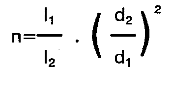
- From R the water electrical resistance, p the resistivity can be calculated as:

- Cells having an optimum of output voltage for a given system may be designed. A cell can be tailored by choice of cell length, diameter, and insulating materials.
- Practical results have shown that a simple cell having the configuration as in Fig. 4, and inserted in a working system in which the system "loops" are very large and hence electrically isolated has worked extremely well. Results of checks against a conventional conductivity cell system are shown in the following table. The tribo-electric cell was inserted in a working water treatment plant and the results calculated from the tribo-electric cell are shown against the readings given by the standard conductivity cell system.

- Tests on the more complex system of Fig. 5 confirm the theoretical tribo-electric model of the system. The voltages generated by the differences of cell insulating materials, differing diameters and differing cell lengths have been as predicted. Inner wall finish of the plastic tube does not appear to have any marked effect in the first instance on cell voltage; in our measurements any variations are lumped with the "tribo-electric" constant K for that particular cell. In all tests, it is assumed that flow-rates have been maintained constant for the period of the measurement, several seconds only.
Claims (11)



Applications Claiming Priority (2)
| Application Number | Priority Date | Filing Date | Title |
|---|---|---|---|
| AU5552/80 | 1980-09-12 | ||
| AUPE555280 | 1980-09-12 |
Publications (3)
| Publication Number | Publication Date |
|---|---|
| EP0059726A1 EP0059726A1 (en) | 1982-09-15 |
| EP0059726A4 EP0059726A4 (en) | 1983-06-08 |
| EP0059726B1 true EP0059726B1 (en) | 1987-03-11 |
Family
ID=3768701
Family Applications (1)
| Application Number | Title | Priority Date | Filing Date |
|---|---|---|---|
| EP81902465A Expired EP0059726B1 (en) | 1980-09-12 | 1981-09-04 | Water purity measurement |
Country Status (7)
| Country | Link |
|---|---|
| US (1) | US4594553A (en) |
| EP (1) | EP0059726B1 (en) |
| JP (1) | JPS6234098B2 (en) |
| CA (1) | CA1162241A (en) |
| IT (1) | IT1146709B (en) |
| NZ (1) | NZ198275A (en) |
| WO (1) | WO1982001071A1 (en) |
Families Citing this family (12)
| Publication number | Priority date | Publication date | Assignee | Title |
|---|---|---|---|---|
| JPS61124850A (en) * | 1984-11-21 | 1986-06-12 | Eruma Kogaku Kk | Apparatus for measuring impurities in ultra-pure water |
| JPS61160038A (en) * | 1985-01-08 | 1986-07-19 | Sumitomo Electric Ind Ltd | particle detector |
| JPS62107099U (en) * | 1985-12-25 | 1987-07-08 | ||
| US4847598A (en) * | 1987-11-27 | 1989-07-11 | Aqua-Tronics, Inc. | Water treatment regeneration system incorporating alternating current excitation and paired operational amplifiers with asymmetrical feedback elements |
| GB9505305D0 (en) * | 1995-03-16 | 1995-05-03 | Philips Electronics Uk Ltd | Electronic devices comprising an array |
| US5747992A (en) * | 1995-06-07 | 1998-05-05 | Abb Power T&D Company Inc. | Materials characterization cell for polarization spectrum and streaming electrification measurements |
| IT1284087B1 (en) * | 1996-06-28 | 1998-05-08 | Enel Spa | SYSTEM FOR MONITORING BIOCIDAL TREATMENTS |
| US5945831A (en) * | 1997-06-10 | 1999-08-31 | Sargent; John S. | Volume charge density measuring system |
| DE19731184C2 (en) * | 1997-07-10 | 1999-10-07 | Atotech Deutschland Gmbh | Device for the analytical monitoring of a bath for electroplating treatment of substrate surfaces |
| GB2335745B (en) * | 1998-03-27 | 2003-04-09 | Pcme Ltd | Improvements in and relating to particle detectors |
| EP3169996A4 (en) * | 2014-07-15 | 2018-01-03 | Alan Joseph Bauer | Devices and methods for identifying a biological or chemical residue in an aqueous sample |
| US10060895B2 (en) * | 2015-12-27 | 2018-08-28 | Light of Detection, Ltd. | Devices and methods for identifying a biological or chemical residue in an liquid sample |
Family Cites Families (13)
| Publication number | Priority date | Publication date | Assignee | Title |
|---|---|---|---|---|
| US1132322A (en) * | 1913-07-09 | 1915-03-16 | Gen Electric | Electrical measuring instrument. |
| US2258045A (en) * | 1938-03-02 | 1941-10-07 | Soren L Christie | Electrode structure for conductivity testing |
| US2315805A (en) * | 1940-05-15 | 1943-04-06 | Frank V Mayo | Fluid meter |
| GB1009721A (en) * | 1961-01-05 | 1965-11-10 | Electronic Switchgear London L | Improvements in or relating to electric measuring arrangements |
| US3296113A (en) * | 1963-10-15 | 1967-01-03 | Union Carbide Corp | Gas-stream monitor |
| US3306320A (en) * | 1965-10-04 | 1967-02-28 | Union Oil Co | Apparatus for detecting change in liquid composition flowing in pipeline |
| US3502965A (en) * | 1966-03-04 | 1970-03-24 | Dow Chemical Co | Control apparatus and system |
| US3368144A (en) * | 1966-03-04 | 1968-02-06 | Dow Chemical Co | Apparatus for measuring charge condition within a solution |
| GB1119393A (en) * | 1966-06-27 | 1968-07-10 | Mawdsley S Ltd | Improvements in or relating to concentration meters |
| GB1225800A (en) * | 1968-11-15 | 1971-03-24 | ||
| GB1387825A (en) * | 1971-06-29 | 1975-03-19 | Plessey Co Ltd | Conductivity cells |
| US3917451A (en) * | 1973-07-02 | 1975-11-04 | Gen Electric | Electrokinetic streaming current detection |
| GB2034902B (en) * | 1978-09-06 | 1982-09-08 | Bestobell Mobrey Ltd | Electrostatic monitoring system |
-
1981
- 1981-09-04 NZ NZ198275A patent/NZ198275A/en unknown
- 1981-09-04 JP JP56502912A patent/JPS6234098B2/ja not_active Expired
- 1981-09-04 WO PCT/AU1981/000127 patent/WO1982001071A1/en not_active Ceased
- 1981-09-04 US US06/719,047 patent/US4594553A/en not_active Expired - Fee Related
- 1981-09-04 EP EP81902465A patent/EP0059726B1/en not_active Expired
- 1981-09-08 CA CA000385403A patent/CA1162241A/en not_active Expired
- 1981-09-11 IT IT68198/81A patent/IT1146709B/en active
Also Published As
| Publication number | Publication date |
|---|---|
| WO1982001071A1 (en) | 1982-04-01 |
| IT8168198A0 (en) | 1981-09-11 |
| US4594553A (en) | 1986-06-10 |
| EP0059726A1 (en) | 1982-09-15 |
| JPS6234098B2 (en) | 1987-07-24 |
| EP0059726A4 (en) | 1983-06-08 |
| CA1162241A (en) | 1984-02-14 |
| NZ198275A (en) | 1984-11-09 |
| JPS57501398A (en) | 1982-08-05 |
| IT1146709B (en) | 1986-11-19 |
Similar Documents
| Publication | Publication Date | Title |
|---|---|---|
| US4594553A (en) | Water purity measurement | |
| EP0039750B1 (en) | Corrosion monitoring process and apparatus for use therein | |
| US3936729A (en) | Conductivity measurement probe | |
| US2859617A (en) | Thermal flowmeter | |
| US3639876A (en) | Probe body for corrosion tests | |
| US4594901A (en) | Electrostatic flow meter | |
| US4426618A (en) | Probe for the continuous in-situ measurement of the corrosion rate of pipes at high temperature or having high-resistivity liquids flowing therethrough | |
| US3374672A (en) | Flowmeter | |
| US3714555A (en) | Conductivity sensor | |
| US3474660A (en) | Thermal conductivity detector | |
| US2258045A (en) | Electrode structure for conductivity testing | |
| GB2210459A (en) | In-line concentric conductivity cell | |
| US3405356A (en) | System including two pairs of voltage electrodes for detecting discontinuities in insulation coatings on conductive conduit | |
| US3526827A (en) | Apparatus for measuring charge condition within a solution | |
| US2987672A (en) | Impedance test apparatus | |
| US3558462A (en) | Probe assembly for corrosion tests | |
| US3445760A (en) | Superconductive magnetometer in which superconductive elements defining a magnetic conduit are connected by weak links | |
| US3111844A (en) | Heat rate measuring apparatus | |
| US3319159A (en) | Method and apparatus for determining the amounts of gases dissolved in liquids | |
| US3150311A (en) | Apparatus for detecting heat protected against false actuation | |
| US3621707A (en) | Thermal conductivity detector assembly | |
| SE456613B (en) | Electrode for Saturation of Relative Capacitivity | |
| JPS593319A (en) | Liquid level detector | |
| JPH049255B2 (en) | ||
| EP1192420B1 (en) | Device for measuring flow rate |
Legal Events
| Date | Code | Title | Description |
|---|---|---|---|
| PUAI | Public reference made under article 153(3) epc to a published international application that has entered the european phase |
Free format text: ORIGINAL CODE: 0009012 |
|
| 17P | Request for examination filed |
Effective date: 19820507 |
|
| AK | Designated contracting states |
Designated state(s): CH DE FR GB LI NL SE |
|
| GRAA | (expected) grant |
Free format text: ORIGINAL CODE: 0009210 |
|
| AK | Designated contracting states |
Kind code of ref document: B1 Designated state(s): CH DE FR GB LI NL SE |
|
| PG25 | Lapsed in a contracting state [announced via postgrant information from national office to epo] |
Ref country code: SE Effective date: 19870311 Ref country code: NL Effective date: 19870311 Ref country code: LI Effective date: 19870311 Ref country code: CH Effective date: 19870311 |
|
| REF | Corresponds to: |
Ref document number: 3175979 Country of ref document: DE Date of ref document: 19870416 |
|
| REG | Reference to a national code |
Ref country code: CH Ref legal event code: PL |
|
| ET | Fr: translation filed | ||
| NLV1 | Nl: lapsed or annulled due to failure to fulfill the requirements of art. 29p and 29m of the patents act | ||
| PLBE | No opposition filed within time limit |
Free format text: ORIGINAL CODE: 0009261 |
|
| STAA | Information on the status of an ep patent application or granted ep patent |
Free format text: STATUS: NO OPPOSITION FILED WITHIN TIME LIMIT |
|
| 26N | No opposition filed | ||
| PGFP | Annual fee paid to national office [announced via postgrant information from national office to epo] |
Ref country code: DE Payment date: 19890814 Year of fee payment: 9 |
|
| PGFP | Annual fee paid to national office [announced via postgrant information from national office to epo] |
Ref country code: FR Payment date: 19890823 Year of fee payment: 9 |
|
| PGFP | Annual fee paid to national office [announced via postgrant information from national office to epo] |
Ref country code: GB Payment date: 19890831 Year of fee payment: 9 |
|
| PG25 | Lapsed in a contracting state [announced via postgrant information from national office to epo] |
Ref country code: GB Effective date: 19900904 |
|
| GBPC | Gb: european patent ceased through non-payment of renewal fee | ||
| PG25 | Lapsed in a contracting state [announced via postgrant information from national office to epo] |
Ref country code: FR Effective date: 19910530 |
|
| PG25 | Lapsed in a contracting state [announced via postgrant information from national office to epo] |
Ref country code: DE Effective date: 19910601 |
|
| REG | Reference to a national code |
Ref country code: FR Ref legal event code: ST |