EP0059586A2 - Engine control system - Google Patents
Engine control system Download PDFInfo
- Publication number
- EP0059586A2 EP0059586A2 EP82300907A EP82300907A EP0059586A2 EP 0059586 A2 EP0059586 A2 EP 0059586A2 EP 82300907 A EP82300907 A EP 82300907A EP 82300907 A EP82300907 A EP 82300907A EP 0059586 A2 EP0059586 A2 EP 0059586A2
- Authority
- EP
- European Patent Office
- Prior art keywords
- engine
- signal
- timing
- fuel
- control
- Prior art date
- Legal status (The legal status is an assumption and is not a legal conclusion. Google has not performed a legal analysis and makes no representation as to the accuracy of the status listed.)
- Granted
Links
Images


Classifications
-
- F—MECHANICAL ENGINEERING; LIGHTING; HEATING; WEAPONS; BLASTING
- F02—COMBUSTION ENGINES; HOT-GAS OR COMBUSTION-PRODUCT ENGINE PLANTS
- F02D—CONTROLLING COMBUSTION ENGINES
- F02D41/00—Electrical control of supply of combustible mixture or its constituents
- F02D41/30—Controlling fuel injection
- F02D41/38—Controlling fuel injection of the high pressure type
- F02D41/40—Controlling fuel injection of the high pressure type with means for controlling injection timing or duration
- F02D41/401—Controlling injection timing
-
- F—MECHANICAL ENGINEERING; LIGHTING; HEATING; WEAPONS; BLASTING
- F02—COMBUSTION ENGINES; HOT-GAS OR COMBUSTION-PRODUCT ENGINE PLANTS
- F02D—CONTROLLING COMBUSTION ENGINES
- F02D41/00—Electrical control of supply of combustible mixture or its constituents
- F02D41/24—Electrical control of supply of combustible mixture or its constituents characterised by the use of digital means
- F02D41/2406—Electrical control of supply of combustible mixture or its constituents characterised by the use of digital means using essentially read only memories
- F02D41/2409—Addressing techniques specially adapted therefor
- F02D41/2422—Selective use of one or more tables
-
- F—MECHANICAL ENGINEERING; LIGHTING; HEATING; WEAPONS; BLASTING
- F02—COMBUSTION ENGINES; HOT-GAS OR COMBUSTION-PRODUCT ENGINE PLANTS
- F02B—INTERNAL-COMBUSTION PISTON ENGINES; COMBUSTION ENGINES IN GENERAL
- F02B75/00—Other engines
- F02B75/02—Engines characterised by their cycles, e.g. six-stroke
- F02B2075/022—Engines characterised by their cycles, e.g. six-stroke having less than six strokes per cycle
- F02B2075/027—Engines characterised by their cycles, e.g. six-stroke having less than six strokes per cycle four
-
- F—MECHANICAL ENGINEERING; LIGHTING; HEATING; WEAPONS; BLASTING
- F02—COMBUSTION ENGINES; HOT-GAS OR COMBUSTION-PRODUCT ENGINE PLANTS
- F02B—INTERNAL-COMBUSTION PISTON ENGINES; COMBUSTION ENGINES IN GENERAL
- F02B3/00—Engines characterised by air compression and subsequent fuel addition
- F02B3/06—Engines characterised by air compression and subsequent fuel addition with compression ignition
-
- F—MECHANICAL ENGINEERING; LIGHTING; HEATING; WEAPONS; BLASTING
- F02—COMBUSTION ENGINES; HOT-GAS OR COMBUSTION-PRODUCT ENGINE PLANTS
- F02D—CONTROLLING COMBUSTION ENGINES
- F02D2200/00—Input parameters for engine control
- F02D2200/02—Input parameters for engine control the parameters being related to the engine
- F02D2200/04—Engine intake system parameters
- F02D2200/0406—Intake manifold pressure
-
- F—MECHANICAL ENGINEERING; LIGHTING; HEATING; WEAPONS; BLASTING
- F02—COMBUSTION ENGINES; HOT-GAS OR COMBUSTION-PRODUCT ENGINE PLANTS
- F02D—CONTROLLING COMBUSTION ENGINES
- F02D2200/00—Input parameters for engine control
- F02D2200/70—Input parameters for engine control said parameters being related to the vehicle exterior
- F02D2200/703—Atmospheric pressure
-
- F—MECHANICAL ENGINEERING; LIGHTING; HEATING; WEAPONS; BLASTING
- F02—COMBUSTION ENGINES; HOT-GAS OR COMBUSTION-PRODUCT ENGINE PLANTS
- F02D—CONTROLLING COMBUSTION ENGINES
- F02D2250/00—Engine control related to specific problems or objectives
- F02D2250/32—Air-fuel ratio control in a diesel engine
-
- F—MECHANICAL ENGINEERING; LIGHTING; HEATING; WEAPONS; BLASTING
- F02—COMBUSTION ENGINES; HOT-GAS OR COMBUSTION-PRODUCT ENGINE PLANTS
- F02D—CONTROLLING COMBUSTION ENGINES
- F02D2250/00—Engine control related to specific problems or objectives
- F02D2250/38—Control for minimising smoke emissions, e.g. by applying smoke limitations on the fuel injection amount
-
- Y—GENERAL TAGGING OF NEW TECHNOLOGICAL DEVELOPMENTS; GENERAL TAGGING OF CROSS-SECTIONAL TECHNOLOGIES SPANNING OVER SEVERAL SECTIONS OF THE IPC; TECHNICAL SUBJECTS COVERED BY FORMER USPC CROSS-REFERENCE ART COLLECTIONS [XRACs] AND DIGESTS
- Y02—TECHNOLOGIES OR APPLICATIONS FOR MITIGATION OR ADAPTATION AGAINST CLIMATE CHANGE
- Y02T—CLIMATE CHANGE MITIGATION TECHNOLOGIES RELATED TO TRANSPORTATION
- Y02T10/00—Road transport of goods or passengers
- Y02T10/10—Internal combustion engine [ICE] based vehicles
- Y02T10/40—Engine management systems
Definitions
- This invention relates generally to engine control systems for regulating engine timing advance and the rack limit position of a fuel pump associated with the engine.
- the operation of a diesel engine is controlled basically by varying the amount of fuel delivered to the engine cylinders and by setting the time of fuel injection into the cylinders relative to the time that the pistons reach top dead center on their compression strokes.
- the amount of fuel delivered to the engine will control the speed of the engine and the timing of fuel injection will affect the efficiency of fuel combustion and engine operation. For example, if the engine speed increases, the timing advance angle of fuel injection must be increased to provide more tire in a cycle of operation for compression, ignition and combustion of the injected fuel.' If the timing advance is too great, however, ignition and combustion will occur too early in the cycle and the efficiency of operation will be adversely affected.
- a typical four-stroke-cycle diesel engine includes a timing shaft which is gear driven by the engine crank shaft at half engine speed, the timing shaft being coupled to the camshaft of a fuel pump by a timing mechanism so that the fuel pump is engine driven and will deliver fuel to half of the engine cylinders during one engine revolution and to the other half'of the cylinders during the next revolution.
- the fuel pump generally includes a movable, throttle-actuated fuel rack, under the control of the engine operation, to vary the amount of fuel delivered by the pump to the engine, up to the maximum amount permitted by a-governor, or rack limit.
- the timing mechanjsm will vary the angular relationship between the rotating timing shaft and fuel pump camshaft to control the time of fuel injection into the cylinders.
- the U.S. Environmental Protection Agency has set Federal emission standards regulating the amount of smoke and gaseous emission which may be exhausted from an engine. Catalytic converters and exhaust gas recirculation have been used to reduce emission to acceptable levels, but at a significant reduction to fuel economy. It is preferable, as in the present invention, to control engine operation so that the fuel in the engine cylinders burns sufficiently and the exhaust components are within the allowable levels. To achieve the desired degree of combustion of the fuel- air mixture in the cylinders, a sufficient amount of air, relative to the amount of fuel in the mixture must be present for combustion and sufficient time must be allowed for the fuel to burn.
- Timing and fuel rack for optimal performance.
- operation of the engine while cold will require settings of optimal timing advance for the many various combinations of engine speed and fuel rate which are different from the optimal timing advance for engine operation at normal running temperatures.
- Optimal timing advance for steady state running will differ between highway and urban operation. They will likewise differ when the engine is accelerating or decelerating.
- the optimal position of the rack limit for a given engine speed and timing will depend upon whether the engine is in a normal running or lugging mode and also upon the altitude at which the engine is operating.
- An engine control system must continuously monitor the actual speed of the engine and the actual timing advance to which the timing mechanism has set the fuel pump. In order to provide precise control over operation, the achieved speed and timing advance must be measured with precision and any changes in speed or timing angle must be noted with as small a lag time as possible. It is desirable to update the status of these monitored conditions many times during a single engine revolution, which introduces another problem in that inherent engine torsionals will cause the instantaneous engine speed to vary somewhat sinusoidally over two full revolutions of the engine. As a consequence it is necessary that the torsional variations in speed be cancelled to provide engine speed indications many times during an engine revolution, with each speed indication being that of the average speed of the engine.
- a control system for an engine system which includes an engine having a crankshaft, an operator-controlled throttle, a fuel pump for supplying fuel to the engine, the fuel pump having a fuel control means for controlling the amount of fuel delivered to the engine-a first engine control means comprising a timing means for setting the engine timing advance and a second engine control means comprising settable fuel control limit means for limiting the maximum amount of fuel deliverable from the fuel pump to the engine, comprises a first condition signal means for monitoring a first condition of the engine in operation and for generating a first condition signal having a value dependent upon the magnitude of the first condition; a second condition signal means for monitoring a .second condition of the engine in operation and for generating a second condition signal having a value dependent upon the magnitude of the second condition; control signal means for storing a plurality of engine control signal values, each corresponding to a desired setting of the first or second engine control means for engine operation at a particular combination of the first and second engine conditions, and for issuing an engine control signal in accordance with the particular values
- the first signal means is arranged to sense the speed of the engine
- the second condition signal means is arranged to sense-the setting of the fuel control means and the engine control means which is set is the timing means.
- the first condition signal means is arranged to cause the speed of the engine
- the second condition signal means is arranged to sense the setting of the timing means
- the engine control means which is set is the fuel control limit means.
- the system may include a third condition-signal means for monitoring a third condition of the engine in operation and for generating a third condition signal having a value dependent upon the magnitude of the third condition, the control signal means also storing a plurality of engine signal values, each corresponding to a desired setting of the first or second engine control means for engine operation at a particular combination of the first and third engine conditions, and for issuing a.second engine control signal in accordance with the particular values of the first and third engine condition signals generated by the first and third condition signal means; and means for setting the other of the engine control means in accordance with the value of the second engine control signal.
- Such separate control signal means can be programmed for desired timing angle advance relative to different combinations of actual engine speed and fuel rack positions for a particular mode of engine operation.
- Selector means can select the proper control signal means in accordance with the particular mode in which the engine is operating, deliver the selected control signal to actuate the timing means, and set the engine timing to the desired value for the existing actual spped and fuel rack position.
- the fuel delivery rate, used to set the rack limit, can be determined by obtaining the optimal fuel/air ratio for the particular speed and timing angle of the engine and by multiplying such fuel/air ratio by the manifold pressure to obtain a value proportional to the maximum amount of fuel to be injected into an engine cylinder.
- instantaneous engine speed signals are measured a plurality of times for each revolution of the engine, and each time an instantaneous speed signal is obtained, the instantaneous speed signals obtained during the past two engine revolutions are averaged to cancel out the effect of engine torsionals so that an average speed signal is obtained a plurality of times for each revolution of the engine.
- digital condition and control signals in binary form are used in the control system and an interpolation method is used in the control signal means to obtain the predetermined control signals by reading a grogrammed memory in accordance with the most significant bits of the control signal, and by interpolating between adjacent programmed signals in accordance with the least significant bits of .the control signals.
- Fig. 1 shows in block diagram form a control system 10 for use with internal combustion engine 11.
- the engine 11 which may be a four-stroke-cycle diesel engine, drives a timing shaft 12 which is coupled, by engine timing means 13, to the fuel camshaft 14 of fuel pump 16.
- timing means 13 will set a minimum phase shift between the timing shaft 12 and fuel camshaft 14 so that fuel pump 16 will deliver fuel from fuel tank 17 to the cylinders of engine 11 at a minimum advance angle, typically 14 0 BTDC, on the compression stroke of the engine pistons.
- Actuation of the timing means'13 by a timing actuator 18 will vary the timing of fuel delivery between minimum and maximum advance angles.
- the fuel pump 16 has a movable fuel rack 21, actuated by an operator-controllable throttle, such as foot pedal 22, to control the amount of fuel delivered by fuel pump 16 to the engine 11.
- an operator-controllable throttle such as foot pedal 22
- depression of the foot pedal 22 will move the fuel rack 21 to the left to increase fuel delivery.
- Release of the foot pedal will move fuel rack 21 to the right, decreasing fuel delivery.
- a reciprocatable rack limit 23, functioning as a governor, will prevent leftward (fuel increasing) movement of fuel rack 21 beyond the limit set by rack limit actuator 24, even though the operator may be then demanding a greater fuel flow by depression of foot pedal 22.
- Rack limit 23 allows rightward movement of fuel rack 21 from the limit position so that the operator may control fuel delivery by foot pedal 22 between minimum fuel delivery and the maximum set by rack limit 23.
- the timing means 13 and fuel rack limit 23 constitute first and second settable engine control means which are themselves controlled by the control system 10 of the present invention.
- This control system 10 has two primary functions. First, the control system 10 functions to cause timing actuator 18 to adjust the engine timing means 13 and thereby set the proper engine timing advance angle for efficient combustion. Second, it functions to cause rack limit actuator 24 to move rack limit 23 and-set it to limit the maximum amount of fuel which the fuel pump can deliver to the,engine cylinders.
- the following conditions of engine operation are continuously monitored and used in the control system 10 to set the engine timing and rack limit position: actual engine timing, engine temperature, throttle position, fuel rack position, actual engine speed, atmospheric pressure and intake manifold pressure.
- a timing sensor 26 continuously monitors the magnitude of the actual timing advance angle set by engine timing means 13 and generates a condition signal having a value dependent upon the magnitude of the timing advance.
- This condition signal is shaped and prescaled by signal conditioner 27, converted from a frequency signal to a digital signal by frequency/digital converter 28 and applied to input line 29 of microprocessor 30.
- the actual timing information is updated every 30 0 or 60 0 of engine rotation, depending upon the particular embodiment of the sensor system used. This will be described subsequently in connection with Figs. 10-17.
- the engine temperature is monitored, as for example by a conventional analog sensor 31 which senses the temperature of the engine coolant, to determine whether the engine is cold, as on start-up, or whether it has reached normal running condition.
- the condition signal from the engine temperature sensor 31 is shaped and prescaled by conditioner 32, converted from analog to digital form by converter 33, and applied to microprocessor input line 34.
- Throttle position is monitored by sensor 36, which may include a potentiometer linked to foot pedal 22, to determine whether the operator has called for acceleration by a depression of the pedal or deceleration by a release of the'pedal.
- sensor 36 which may include a potentiometer linked to foot pedal 22, to determine whether the operator has called for acceleration by a depression of the pedal or deceleration by a release of the'pedal.
- rack position sensor 37 which may include a potentiometer linked to the fuel rack 21, to provide information as to the amount of fuel being delivered by fuel pump 16 to' engine 11.
- Atmospheric pressure and intake manifold pressure are monitored by conventional pressure transducers 39 and 40, respectively.
- the operating condition signals from sensors 36-40 are likewise shaped and prescaled by signal conditioners 32, converted to digital form by converters 41-45, analog-digital or frequency-digital, depending upon the nature of the condition signals, and applied to input lines 46-50 of the microprocessor 30.
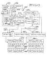
- the microprocessor 30 will respond to the condition signals of the aforementioned sensors 31,36,37,38,39,40 and will output engine control signals to set the engine timing and rack limit to desired and predetermined positions.
- the microprocessor 30 includes a plurality of "maps" for controlling engine timing and rack position.
- the various maps described below each constitute a control signal means for storing a plurality of engine control signals, with each stored control signal having a predetermined value corresponding to a desired setting of one of the -engine control means 13 or 23 for desired operation at a particular combination of engine operating conditions, and for generating an engine control signal having the predetermined value corresponding to the particular value of the engine operating conditions as indicated by the engine condition signals.
- microprocessor 30 includes four maps, 61,62,63 and 64 which are used to control the engine timing.
- the "cold engine map" 61 will have stored within its read-only memory 61a (Fig. 2) a plurality of predetermined engine timing control signals for various combinations of actual engine speed and rack position.
- the values of the timing control signals are determined empirically for_an engine family by carrying out tests on a cold engine (of that family) and compiling a schedule of the optimum values of engine timing for various combinations of engine speed and rack position which will enable the engine to operate with its exhaust to meet the EPA emission standards. After this engine timing schedule has been completed, the values are programmed into the various cells of read-only memory 61a.
- the actual speed and rack position condition signals are applied to map 61 during operation of the vehicle, and the map will output, to timing map selector 65 an engine control signal having the desired value, for the existing speed and fuel rack positions which will set the timing means 13 for engine operation meeting particular emission standards.
- the "transient timing map" 62 will have stored therewithin the proper timing angle values for different engine speeds, such values again having been determined by testing for efficient engine operation when the engine is accelerating or decelerating.
- the actual engine_speed signals are applied to the map with corresponding engine timing angle signals being output to selector 65.
- the "steady state urban timing map” 63 and “steady state highway timing map” 64 are similar to the cold engine-timing map 61 in that maps 63 and 64 have stored therewithin the proper engine timing value for each combination of engine speed and rack position, such values again being predetermined to meet particular standards for urban and highway driving, respectively. Also, as before, the particular timing angle values for the existing engine speed and rack position are output to map selector 65.
- Map selector 65 functions to determine which of the following modes of engine operation exists:' cold,'transient, steady state urban or steady state highway; and to allow the timing angle control signals at the output of the correct one of the maps 61-64 to pass to summing junction 66. If the timing angle control signals indicate that the engine timing should be changed, summing junction 66 will output a signal to a pulse width modulator 67 and a power amplifier 68 will then drive the timing actuator 18 so that the engine timing means 13 will change the engine timing to the desired timing advance angle between timing shaft 12 and fuel camshaft 14.
- the timing sensor 26 senses the engine timing and provides a signal which, after processing by the signal conditioner 27 and frequency to digital converter 28, is output to the microprocessor input line 29. The signal is then fed to summing junction 66 so that the output of the summing junction 66 will cease when the actual engine timing equals the desired engine timing.
- fuel flow must be related to air flow through the engine so that sufficient air is provided for substantially complete fuel combustion.
- the -fuel/air ratio for a given smoke level will vary with engine speed. To prevent engine lugging, more fuel must be injected, but with the fuel/air ratio being controlled to maintain efficient fuel combustion.. During acceleration or deceleration it is desired for the engine 11 to produce maximum power within acceptable smoke limits. Operation at high altitudes requires a decrease in fuel delivery to maintain the proper fuel/air ratio for proper combustion.
- the rate of air flow through the engine will vary with the manifold pressure and the rate of fuel flow will vary with the position of fuel rack 21.
- the maps 71,72,73 and 74 of microprocessor 30 are used in the present system to set the position of rack limit 23 and thereby limit the amount of movement of fuel rack 21 in its fuel-increasing direction so that the engine operator cannot cause the fuel injection rate and consequently the fuel/air ratio to increase beyond that which will produce an acceptable amount of smoke in the engine exhaust.
- the "fuel/air limit map" 71 has programmed therein predetermined values, established by empirical testing, corresponding to the maximum fuel/air ratio for sufficient combustion to meet particular standards for various different combinations of'engine speed and timing within the operating ranges of those conditions.
- map 71 will output a fuel/air signal proportional to the maximum amount of fuel to amount of air of the mixture to be injected into the engine during a stroke thereof for the then existing timing angle and engine speed.
- the fuel/air output signal of map 71 is applied to multiplier 76, along with the condition signal from the intake manifold pressure sensor 40, the latter signal being proportional to the intake pressure, for example, in pounds per square inch gauge. Since the weight of air injected into the engine cylinders with the fuel is proportional to the manifold pressure, multiplier 76 will output a signal proportional to the maximum weight of fuel to be injected during a stroke thereof.
- multiplier 76 The output of multiplier 76 is then multiplied in multiplier 77 by K F , a dimensional constant dependent upon the cylinder size and fuel pump size of the particular engine 11 and fuel pump 16, to give a fuel-delivery signal proportional to the maximum weight of fuel to be delivered to the engine 11 during a piston stroke thereof.
- the fuel-delivery signal from multiplier 77 is input into "rack limit position map” 72, which has stored therewithin rack limit position values, predetermined in accordance with the physical characteristics of the fuel pump 16. - These correspond to the positions at which the rack limit 23 is to be set to give the desired rate of fuel delivery at the existing engine (and hence fuel pump) speed.
- the rack limit position control signals from map 72 are output to map selector 78.
- the "torque rise limit map” 73 is provided to increase the rack limit position and thereby allow the fuel rack 21 to move in a fuel-increasing direction in such mode of operation and thereby prevent engine lugging.
- the torque rise limit map 73 has stored therein rack limit position control signal values, predetermined to allow more fuel to be injected at lower speeds without causing emissions exceeding the particular standards.
- the rack limit position control signals generated by map 73 in response to application of engine speed signals thereto are applied through summing junction 79 to selector 78.
- the "altitude derating map” 74 has stored therewithin rack limit position control signal values, predetermined to meet particular standards, for different values of ambient air pressure.
- the output of map 74 is applied to summing junction 79 which functions to decrease the value of the rack limit position control signal and thus cut back the fuel rack 21 at higher altitudes to maintain an optimal fuel/air ratio.
- Map selector 78 functions as a "least win logic" so that the lowest value of the rack limit position control signals from map 72 and the signal from-summing junction 79 is output to summing junction 81. If such control signal indicates that the position of rack limit 23 is to be changed, summing junction 81 will output a signal to pulse width modulator 82 and power amplifier 83 will then drive the rack limit actuator 24 to cause the desired movement of rack limit 23.
- rack limit sensor 84 which may include a potentiometer coupled to the rack limit 23, and the signal therefrom is conditioned and prescaled by signal conditioner 85, converted to digital form by converter 86 and fed back to the summing junction 81 so that the rack limit actuator 24 will cease to be driven when the actual rack limit position is the same as the desired rack limit position.
- Figs. 2 and 3 illustrate the manner in which an engine timing control signal from the cold engine timing map 61 is obtained for a particular combination of actual engine speed and rack position.
- map includes a read-only memory and the input and.output circuitry of the memory.
- the input line 47 into microprocessor 30 has an eight-bit binary signal, or byte, thereon from rack position sensor 37 representing the actual position of fuel rack 21.
- the signal will have been prescaled to the range of rack movement so that the 256 possible combinations of the byte represent the corresponding number of incremental positions of the rack between its minimum and maximum position.
- input line 48 will have a byte thereon, the particular binary value of which will represent a particular engine speed within the range of minimum and maximum operating speeds.
- the cold engine timing map 61 includes a read-only memory 61a having a three-dimensional schedule with 16 rows and 16 columns, and with a Z-value byte stored within the memory for each combination of a row and column.
- the 256 bytes stored in the memory are determined, for the family of engine with which the control system is to be used, through testing to represent the correct timing angle advance for the various possible combinations of rack position and engine speed which will meet particular standards. If the byte values for the timing angle signal were plotted graphically, the scheduled byte values would lie on a three-dimensional surface 91, at the intersection of the 16 rows thereon corresponding to different values of rack position and the 16 columns corresponding to the different values of actual engine speed.
- the rack position signal on line 47 and the actual engine speed signal on line 48 will be updated at most each time the. engine 11 rotates through 30°, and the binary values of these signals will remain constant between updates.
- the four most significant bits (X 1 ) of the rack position signal on input line 47 will be applied to row selector 101, and the four most significant bits (Y 1 ) of the engine speed signal on input line 48 will be applied to column selector 102 to select the particular row (X 1 ) and column (Y 1 ) of memory 61a.
- the Z 1 byte (Fig. 4) corresponding to the X 1 row and Y1 column is outputted from memory 61a and Z output selector 103 to the Z 1 memory 104.
- the X 1 bits are also applied to stepper 106 which adds a binary 1 to the X 1 value and the stepped (X 1 + 1) bits are then applied to row selector 101, while the Y 1 bits are applied to column selector 1 0 2, to select the (X 1 + 1) row and Y 1 column.
- the Z 2 byte for the (X 1 + 1) row and Y 1 column is then stored into the Z 2 memory 107.
- stepper 108 the (Y 1 + 1) value from stepper 108 and the X 1 value are applied to the map and the corresponding Z 3 byte is stored in the Z 3 memory 109. Subsequently, the (X 1 + 1) bits and (Y 1 + 1) bits are applied to the map 61 and the corresponding Z byte is stored in the Z 4 memory 110.
- the value of Z a is an interpolated value between the values Z 1 and Z 2 for Y 1 and corresponding to the degree of difference between X 1 and X 1 + 1 represented by the x 1 value of the rack position byte.
- function generator 112 will produce an interpolated Z b byte having a value between the Z 3 . and Z 4 bytes (for Y l + 1).
- Za and Zb bytes will be applied to function.generator 113 which produces a Z o byte; Again as seen from Fig. 3, Z o is an interpolated value between the values Z a and Z b (for Y 1 + X l ) corresponding to the degree of difference between Y1 and (Y 1 + 1) represented by the y 1 value of the actual engine speed byte.
- the interpolated Z o byte is then stored in memory, or latch, 114 for use in the control system 10 until the time that the rack position and engine speed input information has been next updated and a new Z o signal has been calculated.
- timing advance angle byte corresponding to particular rack position and engine speed bytes
- memory utilization is only about 400 bytes
- accuracy is 0.4%'
- execution speed is about 800 microseconds.
- the steady state urban timing map 63 and steady state highway timing map 64 are three dimensional maps generally similar to the cold engine timing map of Figs. 2 and 3. Interpolated values of timing advance control signals are obtained from these maps 63,64 in the same manner as that previously detailed for the cold engine timing map 61. Maps 63 and 64 differ from the cold engine maps 62, and from each other, only in the specific desired timing angle control signal that is, the z-valve-stored within the memory cells of these maps for the various combinations of rack position and engine speed. Again, the values of the stored bytes in maps 63 and 64 are determined for an engine family to meet particular standards for urban or highway driving respectively.
- the read-only memories 71a and 72a of fuel/air limit map 71 and rack limit position map 72 are generally illustrated in Figs. 4 and 5, respectively.
- these are three dimensional memories with predetermined bytes stored therein, and interpolated byte signals are obtained therefrom in the same way as described above.
- the memory 71a of fuel/air limit map 71 has stored bytes corresponding to the optimal fuel/air ratio for different combinations of engine speed and the actual timing angle.
- the memory 72a of rack limit position map 72 has stored therewith byte values which will represent the limit position of rack 21 to deliver the desired amount of fuel at a particular engine speed.
- the transient timing map 62 of Fig. 6, includes a two-dimensional read-only memory 62a, having. 16 rows and 16 possible control signal bytes for each particular row.
- the four most significant bits (X l ) of the engine speed byte on input line 48 are applied to the row selector 101 to select the proper row of map 62, and the corresponding Y 1 byte stored in the output is sent to the Y 1 memory 116.
- Stepper 106 adds a binary 1 to X 1 , and the (X 1 + 1) binary bits are applied to the row selector to select the next, (X 1 + 1), row and the corresponding (Y 1 + 1).byte is outputted to the (Y 1 + 1) memory 117.
- the Y 1 and (Y 1 + 1) bytes are then applied to function generator 118, along with the least significant bits x 1 of the engine speed byte to obtain a calculated and interpolated Y o byte corresponding to the particular engine speed byte on input line 48.
- the Y o timing advance angle byte is then sent broadside to a Y o memory or latch 119 for use in controlling the timing means 13 until the next Y o byte is calculated.
- the memory portion 74a of the altitude derating map 74 is illustrated in Fig. 7 and has stored therewithin rack position bytes for different values of barometric pressure.
- the values of the stored rack limit position control signals decrease, as at 121, for low values of barometric pressure.
- the purpose for the altitude derating map 74 in the present control system is to cut back the rack (by-a lower value rack limit position control signal) at higher altitudes so as to provide an optimal air-fuel ratio.
- the values stored within the map 74 are predetermined to meet particular standards.
- the memory portion 73a at the torque rise limit map 73 is illustrated in Fig. 8, and has stored therewithin rack limit position control data, in byte form, for different values of engine speed. As previously mentioned, when engine speed decreases due to load the rack will inherently move to provide more fuel to the engine, and the torque rise table will- limit such movement so that exhaust emissions will be held to proper limits.
- the dotted line 122.in Fig. 8 shows the correction that will be imposed under lugging conditions by the rack cut-back of altitude derating map 74 at high elevations.
- Fig. 9 illustrates a form of selector 65 which may be used to determine which of the timing maps 61-64 is to be used to control the timing advance angle of the engine 11:
- the engine temperature signal from the engine temperature sensor 31 is applied to gate control 131.
- the engine temperature sensor 31 will output a low temperature value causing the Q output to close gate 132, allowing the timing advance angle control signal from the cold engine timing map 61 to pass through to the output 133 of selector 65.
- Gates 134,135 and 136 will be held open, so that the outputs of maps 62,63 and 64 will be prevented from appearing at the selector output 133.
- gate control 131 will open gate 132 to disconnect the cold engine timing map 61 from the selector output and will close gates 134-136 to allow the appropriate map 62,63 or 64 to control the timing advance angle.
- the throttle'position signal from sensor 36 is applied to gate control 137.
- the throttle position signal will be generated by sensor 36 only when. the operator has substantially depressed the pedal for acceleration or substantially released the pedal for deceleration.
- gate control 137 will set the Q output causing gate 138 to close connecting the transient timing map 62 to the selector output 33 (if the engine is at normal operating temperature) and will cause gates 139 and 140 to open so that the steady state maps 63 and 64 cannot control the timing advance angle.
- the throttle position signal ceases (i.e.
- gate control 137 when the operator ceases calling for significant acceleration or deceleration) gate control 137 will open gate 138 to disconnect the transient timing map 62 from the selector output 133 and will close gates 139 and 140 to enable the timing advance angle to be controlled by one or the other of the steady state maps 63 or 64.
- the throttle-position signal is also applied to the urban condition detector 142 together with the signal from a differentiator 143.
- the engine speed signal from the engine speed sensor 38 is applied to differentiator 143 which will output an engine-speed-change signal in response to changes in engine speed.
- the urban condition detector 142 functions to generate a signal upon a concurrence of the throttle position signal and an engine-speed-change signal from differentiator 143, i.e. when the operator is calling for acceleration and the engine speed is increasing, or when the operator is calling for deceleration and the engine speed is slowing.
- the signals from detector 142 are applied to counter 144 and if-the count of such signals reaches a predetermined number before the counter 144 is reset by timer 145, the Q output of counter 144 will set the gate control 146 so that its Q output will close gate 147 to connect the steady state urban timing map 63.-to selector output 133 (provided that gates 139 and 134 are also closed.)
- counter 144 After being reset, counter 144 will again count the signals from urban condition detector. As long as the number of such signals during the period of timer 145 remains above the predetermined number, gate control 146 will remain set and the steady state urban timing map 63 will remain connected to selector output 133. If, however, the count of signals from detector 143 does not exceed the predetermined number by the time of the reset signal from timer 145, the reset signal and the Q output of counter 144 will cause AND gate 148 to reset gate control 146. Gate 147 will open and the Q output of gate control 146 will cause gate 149 to close, connecting the steady.state highway timing map 64 to the selector output 132.
- the time period of timer 145 and the number of signals from detector 142 needed to set gate control 146 are chosen to distinguish between driving conditions which occur in urban or highway driving.
- Urban driving requires frequent accelerations or decelerations because of stop signs, heavy traffic and the like.
- Highway driving on the other hand, will require only occasional accelerations or decelerations, as when another vehicle is being passed.
- the engine speed will decrease or increase without change in throttle positions, such as when the vehicle goes up or down grades, but such changes in engine speed will not cause the urban condition detector 142 to output a signal to counter 144 since a throttle position signal is concurrently required for such detector signal.
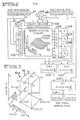
- Fig. 10 illustrates portions of interest of a conventional engine and fuel system.
- a crankshaft 211 of engine 11 has a flywheel 212 fixed thereon and meshed gears 213 and 214, on crankshaft 211 and timing shaft 12, respectively, transmit engine rotation to the timing shaft 12.
- gear ratio of gears 213 and 214 is such that the timing shaft 12 is driven at half the speed of the engine 11.
- Timing means 13 rotatively drives a camshaft 14 of fuel pump 16 by the timing shaft 12 and is arranged to vary, within a predetermined range,.the angular relationship between the timing shaft 12 and fuel pump camshaft 14 so that fuel is delivered to the engine cylinders at the proper time in the cycle of engine operation.
- timing means 13 may comprise a differential type assembly. The system may be set initially to deliver fuel from fuel tank 17 and fuel line 233 to the engine 11 at a minimum advance (typically 14 0 ) before top dead center of the engine pistons in the appropriate half of the cycle.
- the timing advance-actuator 18 means will cause the timing means 13 to set the advance angle of fuel delivery at a desired value greater than minimum during operation of the engine 11, as by actuation of solenoid valve 234 in response to the output of amplifier 68.
- the timing advance means will cause the fuel camshaft 14 to be driven at the same speed as that of timing shaft 12, but the angular relationship of the two shafts will be varied from the minimum advance relationship to provide the correct timing for the given conditions.
- the fuel pump 16 has a movable fuel rack 21, which-controls the amount of fuel flowing through the fuel pump 16. As mentioned previously, the fuel rack 21 is moved in response to foot pedal 22, and its movement is limited by fuel rack limit 23. Fuel rack limit 23 may be the piston of hydraulic cylinder 2-41, with piston movement being controlled by actuation of solenoid valve 242 in response to the output of amplifier 83. :
- a first rotation responsive means 246 is provided for generating a signal each successive time that engine 11 has rotated through 360/N degrees, N being an integer.
- the rotation responsive means 246 includes a plurality of holes 247 in flywheel 212, equi-angularly spaced relative to, and equi-distantly spaced from the axis of the flywheel. Holes 247 thus provide surface irregularities on the ferromagnetic flywheel 212 which.constitute magnetically-sensible features which rotate in a circular path around the crank shaft 211.
- the first rotation responsive means 246 may be associated with gear 213, or gear 214 on the timing shaft,12, the gear being provided with holes 247.
- Rotation responsive means 246 also includes a first signal generating means 248 for generating a first signal 249 (Fig. 14) in response to each movement of a flywheel hole 247 past a predetermined point in the circular'path of movement of holes 247.
- the signal generating means 248 includes a fixed magnetic sensor 250 located adjacent the circular path of movement, the location of the sensor 250 thus determining the predetermined point in the path of movement of holes 247.
- flywheel 212 has twelve holes 247 and thus a first signal 249 will be generated each time the engine rotates through 360/12, or 30 degrees. Since timing shaft 12 is driven at half the engine speed, a first signal will be generated each time the timing shaft rotates through 15 degrees.
- a second rotation responsive means 251 is provided for'generating a second signal each successive time that the engine has rotated through 360/N degrees.
- the rotation responsive means 251 fixed to fuel camshaft 14 for rotation therewith includes a circular member 252 having a plurality of holes 253 equi-angularly,spaced around member 223 and all at the same distance from the axis of camshaft 14.
- holes 253 provide magnetically-sensible, surface irregularity features which move in a circular path around camshaft 14.
- Rotation responsive means 251 also includes a second signal generating means 254 for generating a second signal 255 (Fig. 14) in response to each movement of a hole 253 past a predetermined point in the circular-path of movement of holes 253.
- the signal generating means 254 includes a fixed magnetic sensor 256 located adjacent the circular path of movement of holes 253. Again, the fixed location of sensor 256 determines the predetermined point in the path of movement of holes 253.
- circular member 252 has twenty-four holes 253, and thus a second signal 255. will be generated for each 15 degrees of rotation of camshaft 14. Or, since fuel camshaft 14 is driven at half engine speed, a second signal 255 will be. generated for each 30 degrees of rotation of engine 10.
- the number of first signals 249 from the flywheel sensor 250 will be equal to the number of. second signals 255 from the fuel camshaft sensor 256 during any given length of time, such as the time that it takes the engine crank shaft 211,_or the time that it takes either of the timing or fuel camshaft 12 or 14 to rotate through a full revolution, and the time interval between consecutive first signals 249 will be equal to the time interval between consecutive second signals 258.
- the phase relationship of the first and second signals 249 and 255 will vary in accordance with the timing advance angle set by the timing means 13.
- the first and second signals from the flywheel sensor 250 and fuel camshaft sensor 256 are then sent to the data processor 260 wherein the signals are used to generate digital signals proportional to the engine speed and the timing advance angle of the fuel pump.
- the engine speed and timing advance angle signals are also generated in a manner so as to cancel out the effect of engine torsionals.
- Piston-operated internal-combustion engines have inherent imbalances which cause regularly occurring disturbances in the operation of the engine.
- crank shaft 211 Since one-half of the pistons drive the crank shaft 211 during one complete engine revolution and the other one-half of the pistons drive the crank shaft 211 during the subsequent revolution, and since these two sequences have a discrete set of disturbances associated with them, the two revolutions will never have precisely the same characteristics.
- the crank shaft 211 will always have 'a somewhat different amount of power transmitted to it during one full revolution than the one immediately preceding or following.
- the inherent engine imbalances will produce a half order torsional having a full cycle during two full engine revolutions, a first order torsional occurring in one full engine revolution, a second order torsional occurring in one-half-an engine revolution, and so on with higher order torsionals of decreasing magnitude.
- the result of the torsionals is that the instantaneous engine speed will vary as the engine rotates.
- the mass of the drive system and flywheel will damp the effect of the imbalances but the actual speed will still vary sinusoidally through two engine revolutions, with the engine alternately accelerating and decelerating.
- the instantaneous speed of the engine 11 is determined N/M times for each full revolution of the engine, N being an integer representing the number of times that a signal from the flywheel sensor 249 is generated during a full engine revolution, and M being either 1 or 2,'depending upon whether a new, updated speed determination is made each time a flywheel sensor signal 249 is generated or whether a new, updated speed determination is made for every other flywheel sensor signal 249.
- N/M-P consecutive instantaneous speed determinations are then added and divided by (N/M)P, P being an integer representing a number of full engine revolutions, to obtain an average engine speed during the P number of engine revolutions.
- Fig. 13 illustrates one embodiment of data processor 260 which can be used to generate average speed and average timing advance angle signals in response to generation of signals by the flywheel and fuel camshaft sensors 250 and 256.
- flywheel sensor 250 will generate a series of first signals 249 in response to each passage of a flywheel hole 247 therepast, with a time lapse of T 1 between consecutive leading edges of the signals.
- the fuel camshaft sensor 256 will likewise generate a series of second signals 255, each also having a time lapse of T , between consecutive signals.
- the first and second signals 249 and 255 will be out of phase with each other in an amount dependent upon the position of the timing means 13, and there will be a time lapse of T 2 between the leading edge of a second signal 255 and the leading edge of the next successive first signal 249.
- the time lapse T 1 is inversely proportional to engine speed -- the faster the speed of engine rotation, the shorter the time of T 1 and vice versa.
- the time lapse T 2 for any given phase relation between the timing and fuel camshaft 12 and 14 is also inversely proportional to engine speed.
- the ratio of T 2 /T 1 is proportional to the degree of phase relation between the timing and fuel camshafts 12 and 14, and will remain constant for any given degree of phase relation regardless of engine speed.
- a fixed frequency clock 265 generates a continuous series of high frequency clock pulses which are applied to the inputs of the T 1 gate 266 and the T 2 gate 267.
- the first signal 249 from the flywheel sensor 250 is applied to flip-flop 268 so that a low Q flip-flop output from alternate first signals 249 will cause the T1 gate 266 to close and a high Q flip-flop output from the next successive first signal 249 will cause the T 1 gate 266 to open.
- the T 1 pulse counter 269 will have a count of the number of clock pulses occurring during the time interval beginning and ending with successive first signals 249. Since clock 265 has a fixed frequency, the count of the T 1 pulse counter 269 will be inversely proportional to the speed of the engine.
- the count T 1 (t), i.e. the instantaneous count for 30° of engine revolution, in the T 1 counter is applied to divider 271, along with a constant K R , the divider 271 functioning to divide the constant K R by the count T l (t) and serving as a speed-indicating means for generating an instantaneous speed-indicating signal, SPD(t), which is inversely proportional to the count T l (t) of the counter 266 and is thus directly proportional to the instantaneous engine speed measured during the time the T 1 gate 266 was closed.
- the constant K R is chosen to scale the T l (t) count so that a useful eight-bit binary coded SPD(t) signal is obtained by divider 271.
- the SPD(t) signal is then applied to the input cell of shift register 272, the shift register having NP/M number of cells.
- shift register 272 would have 12 cells.
- the successively generated speed-indicating signals SPD(t) will be applied to shift register 272 so that the shift register will have, at any time, the 12 most recent successive speed-indicating signals therein.
- the signals in all of the shift register cells are applied to the speed averaging means 273, shown here as an adder-divider, which adds the NP/M number of speed-indicating signals and divides the sum by NP/M to generate an average speed signal.
- the adder-divider 273 outputs the average speed signal into the 8-bit memory, or latch 74 which stores such signal until the next average speed signal is generated.
- the 8-bit or byte, signal is applied to input line 48 of microprocessor 30 and used as an input to the four timing maps 61-64, the fuel/air limit map 71, the torque rise limit map 73 and the rack limit position map 72.
- the engine speed signal is also applied to differentiator 143 which controls the function of the timing map selector 65.
- the Q output of flip-flop 268 is also applied to AND gate 276 to enable the next successive second signal 255 from the fuel camshaft sensor 256 to close the T 2 gate 267.
- the T 2 gate 267 will be opened in response to the same first signal 249 which opens the T 1 gate 266.
- the T 2 counter 277 will count clock pulses passing through gate 267 and will thus obtain a count of the number of clock pulses occurring in the time interval beginning with a second signal 255 and ending with the next successive first signal 249.
- the gates 266 and 267 and pulse counters 269 and 277 constitute a counting means 278 for counting clock pulses occurring in the time interval T 1 beginning and ending with consecutive first signal 249 from the pulse generating means 248 and for counting clock pulses occurring in the time interval T 2 beginning with a second signal 255 from pulse generating means 251 and ending with the next successive first signal 249 from pulse generating means 248.
- the timing means 13 When the engine is first started, the timing means 13 will be a minimum advance, e.g. 14° BTDC, and there will be an initial angular phase relation between the timing and fuel camshafts 12 and 14 to cause fuel delivery to the engine with minimum advance. Likewise, there will be an initial phase relation between the first signals 249 from the flywheel sensor 250 and the second signal 255 from the fuel camshaft sensor 256, corresponding to minimum advance, with a second signal 256 preceding the next successive first signal 255 by a particular degree of rotation. It is an aspect of the present embodiment that the circular member 252 on the fuel camshaft 14-- can be randomly fixed thereto, without regard to whether its holes 253 have any particular orientation with respect to the holes 247 of the flywheel.
- the engine At engine start up, the engine will initially operate at minimum advance angle.
- Dividing one count by the other gives a signal which is proportional to the degree of engine rotation between a second signal 255 and the next succeeding first signal 249 relative to the degree of engine notation between consecutive first signals 249. Such signal is thus independent of engine speed.
- the constant K T scales that divided counts to provide a useful binary coded signal, with the constant K T also representing the angle that the engine turns between successive first signals.
- T l T 2
- the signal TIM would represent a timing advance of 30°.
- the initial timing advance angle signal TIM(o) is then stored for use in the data processor 260 until the engine is shut down.
- 30° of engine rotation are required to develop the counts in counters 269 and 277 and a new timing advance signal TIM(t) will be generated in the next 30° of engine rotation. Accordingly, six new timing advance signals TIM(t) will be generated for each full engine revolution.
- the initial and instantaneous timing advance signals TIM(o) and TIM(t) are applied to logic circuit 281. If the magnitude of the instantaneous timing advance signal TIM(t) is not less than the magnitude of the initial timing advance signal TIM(o), function generator 282 will subtract the initial timing advance signal TIM(o) from the instantaneous timing advance signal TIM(t) which is proportional to the actual degree of timing advance produced by the timing means 13.
- function generator 283 will add the angle K T to the instantaneous timing advance signal TIM(t) and then subtract the initial timing advance signal TIM(o) therefrom to generate a positive true timing signal TIM(t) to which is proportional to the actual angle of advance from minimum advance.
- the successive true timing advance signals TIM(T) are entered into and advanced through the NP/M cell shift register 284. Each time a new TIM(T) signal is entered into shift register 284, the TIM(T) signals in the shift register cells are applied to adder-divider 285 which functions as an angle-averaging means for generating an average timing angle advance signal. Such signal is output into the 8-bit memory 286, or latch, which stores the signal until the next average timing advance angle signal is generated.
- the byte in memory 286 is applied to input line 29 of microprocessor 30 and used as an input to the fuel/air limit map 71.
- Fig. 15 illustrates a modification of the system of Fig. 14, which may be used in an engine system wherein the timing advance means 13 is physically constrained so that a maximum timing advance of 20 0 from minimum advance is obtainable.
- the TIM(o) and TIM(t) timing advance angle signals are applied to the TIM(o) 10° and TIM(t) 10 0 logic circuits 281a and 281b and the function generators 282 and 283 are actuated in accordance with the logic circuits to generate the desired true timing advance signals TIM(T).
- the circular member 252 may be randomly fixed on the fuel camshaft 14, but the average speed and average timing advance signals will be updated only 'six times for each full engine revolution.
- the circular member 252 must be more accurately located on the fuel camshaft 14 (or the fixed location of the fixed sensors 249 and/or 255 must be more accurately chosen) so that at minimum timing advance a particular second signal 255 is generated slightly before a particular first signal 249 and at maximum timing advance such second signal is generated before the same first signal 249 but after the preceding first signal 249.
- the circular member 252 should be oriented on the fuel camshaft 14 so that, at minimum timing advance angle, a second signal 255 will be generated somewhere between one and nine degrees in advance of a first signal 249.
- the data processor 260a of Fig. 16 differs from that of Fig. 13 in that each second signal 255 from the fuel camshaft sensor 256 is used to close the T 2 gate 267, with the gate being opened by the next first signal 249 from the flywheel sensor 250.
- a new count by the T 2 counter 277 of the clock pulses from the fixed frequency clock 265 is obtained each time the engine rotates through 30°, or, twelve times during a full engine rotation.
- the data processor 260a also differs in that gate 266 is closed by each first signal 249 from the flywheel sensor 250 and is opened by the next occurring second signal 255 from the fuel camshaft sensor 256.
- the clock pulses during this period are then counted by the T 3 counter 269a, with the count being proportional to the length of this time period.
- the T 3 count is sent to adder 269b, enabling the T 3 counter 269a to be reset.
- the time periods T 2 ⁇ T 3 will always equal the time period T l .
- gates 266 and 267, pulse counters 269a and 277 and adder 269b constitute counting means 278 for counting clock pulses occurring in the time interval T 1 beginning and ending with consecutive first signals from the pulse generating means 248 and for counting clock pulses occurring in the time interval T 2 beginning with a second signal 255 from pulse generating means 251 and ending with the next successive first-signal 249 from pulse generating means 248.
- the T 1 signal from adder 269b, generated for each 30° of engine revolution, is then sent to divider 271, and an average speed indicating signal is generated by the shift register 272 (with 24 cells) and adder-divider 273 as before.
- 24 instantaneous speed indicating signals will be averaged for two full engine revolutions and a new average speed indicating signal will be generated for each successive 30° of engine revolution.
- the T 1 signal from adder 269b and the T 2 signal from counter 277 will also be applied, as before, to dividers 279 and 280 wherein an initial timing advance signal TIM(o) and subsequent instantaneous timing advance signals TIM(t) are generated.
- control system 10 of the present invention provides an integrated and automatic regulation of engine timing and maximum allowable fuel rate so that maximum engine performance can be realized, in its various modes of operation, while limiting smoke and emissions to required levels.
- the disclosed control system is particularly useful with four-stroke-cycle diesel engines used in highway trucks.
Abstract
Description
- This invention relates generally to engine control systems for regulating engine timing advance and the rack limit position of a fuel pump associated with the engine.
- The operation of a diesel engine is controlled basically by varying the amount of fuel delivered to the engine cylinders and by setting the time of fuel injection into the cylinders relative to the time that the pistons reach top dead center on their compression strokes. In general, the amount of fuel delivered to the engine will control the speed of the engine and the timing of fuel injection will affect the efficiency of fuel combustion and engine operation. For example, if the engine speed increases, the timing advance angle of fuel injection must be increased to provide more tire in a cycle of operation for compression, ignition and combustion of the injected fuel.' If the timing advance is too great, however, ignition and combustion will occur too early in the cycle and the efficiency of operation will be adversely affected.
- A typical four-stroke-cycle diesel engine includes a timing shaft which is gear driven by the engine crank shaft at half engine speed, the timing shaft being coupled to the camshaft of a fuel pump by a timing mechanism so that the fuel pump is engine driven and will deliver fuel to half of the engine cylinders during one engine revolution and to the other half'of the cylinders during the next revolution. The fuel pump generally includes a movable, throttle-actuated fuel rack, under the control of the engine operation, to vary the amount of fuel delivered by the pump to the engine, up to the maximum amount permitted by a-governor, or rack limit. The timing mechanjsm will vary the angular relationship between the rotating timing shaft and fuel pump camshaft to control the time of fuel injection into the cylinders.
- _ The U.S. Environmental Protection Agency (EPA) has set Federal emission standards regulating the amount of smoke and gaseous emission which may be exhausted from an engine. Catalytic converters and exhaust gas recirculation have been used to reduce emission to acceptable levels, but at a significant reduction to fuel economy. It is preferable, as in the present invention, to control engine operation so that the fuel in the engine cylinders burns sufficiently and the exhaust components are within the allowable levels. To achieve the desired degree of combustion of the fuel- air mixture in the cylinders, a sufficient amount of air, relative to the amount of fuel in the mixture must be present for combustion and sufficient time must be allowed for the fuel to burn.
- In order to accomplish this, it is necessary to regulate the operation of the fuel pump so that the amount of fuel which the operator can demand, by throttle operation, to be delivered to the cylinders, be limited to that which can be burned with the necessary degree of combustion in the available air in the fuel- air mixture and at the same time fuel injection timing must be closely controlled.
- As a consequence, there is a need for an automatic engine control which will precisely regulate engine timing and rack limit so that emission standards are met with the least possible loss of overall engine efficiency.
- There are considerable problems involved in providing such an engine control.
- If an engine were to be operated at a constant speed and constant load, it would be a relatively simple matter to set the timing and fuel rack for optimal performance. However, that is not the case where vehicle engines are concerned, since many different modes of engine operation are necessary. Operation of the engine while cold will require settings of optimal timing advance for the many various combinations of engine speed and fuel rate which are different from the optimal timing advance for engine operation at normal running temperatures. Optimal timing advance for steady state running will differ between highway and urban operation. They will likewise differ when the engine is accelerating or decelerating. The optimal position of the rack limit for a given engine speed and timing will depend upon whether the engine is in a normal running or lugging mode and also upon the altitude at which the engine is operating.
- The various different modes of engine operation, each requiring different settings of engine timing and/or rack limit position, make it necessary that the engine control be able to identify the particular mode in which the engine is operating and to set the timing advance and/or rack limit for optimal performance at the various combinations of engine speed and fuel delivery that are encountered in such mode.
- An engine control system must continuously monitor the actual speed of the engine and the actual timing advance to which the timing mechanism has set the fuel pump. In order to provide precise control over operation, the achieved speed and timing advance must be measured with precision and any changes in speed or timing angle must be noted with as small a lag time as possible. It is desirable to update the status of these monitored conditions many times during a single engine revolution, which introduces another problem in that inherent engine torsionals will cause the instantaneous engine speed to vary somewhat sinusoidally over two full revolutions of the engine. As a consequence it is necessary that the torsional variations in speed be cancelled to provide engine speed indications many times during an engine revolution, with each speed indication being that of the average speed of the engine.
- In order to set the rack limit to control the maximum allowable amount of fuel which the operator can cause to be injected at any time into the engine, it is first necessary to determine the optimal amount of fuel which can be burned with the desired efficiency in an engine cylinder. There has been a problem in determining this amount since this rate of fuel delivery is an interdependent function of engine timing advance, engine speed and amount of air introduced into the cylinders along with the fuel.
- According to the invention a control system for an engine system which includes an engine having a crankshaft, an operator-controlled throttle, a fuel pump for supplying fuel to the engine, the fuel pump having a fuel control means for controlling the amount of fuel delivered to the engine-a first engine control means comprising a timing means for setting the engine timing advance and a second engine control means comprising settable fuel control limit means for limiting the maximum amount of fuel deliverable from the fuel pump to the engine, comprises a first condition signal means for monitoring a first condition of the engine in operation and for generating a first condition signal having a value dependent upon the magnitude of the first condition; a second condition signal means for monitoring a .second condition of the engine in operation and for generating a second condition signal having a value dependent upon the magnitude of the second condition; control signal means for storing a plurality of engine control signal values, each corresponding to a desired setting of the first or second engine control means for engine operation at a particular combination of the first and second engine conditions, and for issuing an engine control signal in accordance with the particular values of the first and second engine condition signals generated by the first and second condition signal means; and means for setting one of the engine control means in accordance with the value of the generated engine control signal.
- Preferably, the first signal means is arranged to sense the speed of the engine, the second condition signal means is arranged to sense-the setting of the fuel control means and the engine control means which is set is the timing means.
- Alternatively, the first condition signal means is arranged to cause the speed of the engine, the second condition signal means is arranged to sense the setting of the timing means, and the engine control means which is set is the fuel control limit means.
- For further control, the system may include a third condition-signal means for monitoring a third condition of the engine in operation and for generating a third condition signal having a value dependent upon the magnitude of the third condition, the control signal means also storing a plurality of engine signal values, each corresponding to a desired setting of the first or second engine control means for engine operation at a particular combination of the first and third engine conditions, and for issuing a.second engine control signal in accordance with the particular values of the first and third engine condition signals generated by the first and third condition signal means; and means for setting the other of the engine control means in accordance with the value of the second engine control signal.
- Such separate control signal means, can be programmed for desired timing angle advance relative to different combinations of actual engine speed and fuel rack positions for a particular mode of engine operation. Selector means can select the proper control signal means in accordance with the particular mode in which the engine is operating, deliver the selected control signal to actuate the timing means, and set the engine timing to the desired value for the existing actual spped and fuel rack position.
- The fuel delivery rate, used to set the rack limit, can be determined by obtaining the optimal fuel/air ratio for the particular speed and timing angle of the engine and by multiplying such fuel/air ratio by the manifold pressure to obtain a value proportional to the maximum amount of fuel to be injected into an engine cylinder.
- Advantageously, instantaneous engine speed signals are measured a plurality of times for each revolution of the engine, and each time an instantaneous speed signal is obtained, the instantaneous speed signals obtained during the past two engine revolutions are averaged to cancel out the effect of engine torsionals so that an average speed signal is obtained a plurality of times for each revolution of the engine.
- - In a further aspect of the invention digital condition and control signals in binary form are used in the control system and an interpolation method is used in the control signal means to obtain the predetermined control signals by reading a grogrammed memory in accordance with the most significant bits of the control signal, and by interpolating between adjacent programmed signals in accordance with the least significant bits of .the control signals.
- One example of a control system according to the invention, together with modifications thereof, will now be described with reference to the accompanying drawings in which:-
- Figure 1 is a block diagram of an engine-fuel pump system and a control system therefor utilizing the present invention;
- Figure 2 is a block diagram of one of the control signal means of Figure 1, and in particular, the cold engine timing map;
- Figure 3 is a three dimensional graph illustrating the memory portion of the map of Figure 2;
- Figures 4 and 5 illustrate the three-dimensional schedules of the fuel/air limit and rack limit position maps of Figure 1;
- Figure 6 is a block diagram of one of the two dimensional maps of Figure 1 and in particular, the transient timing map;
- Figures 7 and 8 illustrate the two-dimensional schedules of the altitude derating and torque rise limit maps of Figure 1;
- Figure 9 is a block diagram of the timing map selector of Figure 1;
- Figure 10 is a generally schematic view of the physical components of the engine fuel system of Figure 1 and the sensors used therewith for sensing engine speed and timing advance angle;
- Fig. 11 is a graph illustrating the effect of engine torsionals;
- Fig. 12 is a graph illustrating the torsional cancellation technique by which average engine speed signals are obtained for use in the present invention;
- Fig. 13 is a block diagram of one form of the data processors of Fig. 10;
- Fig. 14 is a timing chart of the signals produced by the flywheel and fuel camshaft sensors of Fig. 10 and used in the data processor of Fig. 13;
- Fig. 15 is a modification of a portion of the data processor of Fig. 13;
- Fig. 16 is block diagram of an alternate form of the data processor of Fig. 10;
- Fig. 17 is a timing chart of the signals produced by the flywheel and fuel camshaft sensors of Fig. 10and used in the-data processor of Fig. 16.
- Referring now to the drawings, wherein a preferred embodiment of the invention is illustrated, Fig. 1 shows in block diagram form a
control system 10 for use withinternal combustion engine 11. Theengine 11, which may be a four-stroke-cycle diesel engine, drives atiming shaft 12 which is coupled, by engine timing means 13, to thefuel camshaft 14 offuel pump 16. As is conventional,timing means 13 will set a minimum phase shift between thetiming shaft 12 andfuel camshaft 14 so thatfuel pump 16 will deliver fuel fromfuel tank 17 to the cylinders ofengine 11 at a minimum advance angle, typically 140 BTDC, on the compression stroke of the engine pistons. Actuation of the timing means'13 by atiming actuator 18 will vary the timing of fuel delivery between minimum and maximum advance angles. - The
fuel pump 16 has amovable fuel rack 21, actuated by an operator-controllable throttle, such asfoot pedal 22, to control the amount of fuel delivered byfuel pump 16 to theengine 11. As best shown in Fig. 1, depression of thefoot pedal 22 will move thefuel rack 21 to the left to increase fuel delivery. Release of the foot pedal will movefuel rack 21 to the right, decreasing fuel delivery. Areciprocatable rack limit 23, functioning as a governor, will prevent leftward (fuel increasing) movement offuel rack 21 beyond the limit set byrack limit actuator 24, even though the operator may be then demanding a greater fuel flow by depression offoot pedal 22.Rack limit 23 allows rightward movement offuel rack 21 from the limit position so that the operator may control fuel delivery byfoot pedal 22 between minimum fuel delivery and the maximum set byrack limit 23. - The timing means 13 and
fuel rack limit 23 constitute first and second settable engine control means which are themselves controlled by thecontrol system 10 of the present invention. Thiscontrol system 10 has two primary functions. First, thecontrol system 10 functions to causetiming actuator 18 to adjust the engine timing means 13 and thereby set the proper engine timing advance angle for efficient combustion. Second, it functions to causerack limit actuator 24 to moverack limit 23 and-set it to limit the maximum amount of fuel which the fuel pump can deliver to the,engine cylinders. - Preferably, the following conditions of engine operation are continuously monitored and used in the
control system 10 to set the engine timing and rack limit position: actual engine timing, engine temperature, throttle position, fuel rack position, actual engine speed, atmospheric pressure and intake manifold pressure. - A
timing sensor 26 continuously monitors the magnitude of the actual timing advance angle set by engine timing means 13 and generates a condition signal having a value dependent upon the magnitude of the timing advance. This condition signal is shaped and prescaled bysignal conditioner 27, converted from a frequency signal to a digital signal by frequency/digital converter 28 and applied to inputline 29 ofmicroprocessor 30. As will be described hereinafter, the actual timing information is updated every 300 or 600 of engine rotation, depending upon the particular embodiment of the sensor system used. This will be described subsequently in connection with Figs. 10-17. - The engine temperature is monitored, as for example by a
conventional analog sensor 31 which senses the temperature of the engine coolant, to determine whether the engine is cold, as on start-up, or whether it has reached normal running condition. The condition signal from theengine temperature sensor 31 is shaped and prescaled byconditioner 32, converted from analog to digital form byconverter 33, and applied tomicroprocessor input line 34. - Throttle position is monitored by
sensor 36, which may include a potentiometer linked tofoot pedal 22, to determine whether the operator has called for acceleration by a depression of the pedal or deceleration by a release of the'pedal. The actual position offuel rack 21 is sensed byrack position sensor 37, which may include a potentiometer linked to thefuel rack 21, to provide information as to the amount of fuel being delivered byfuel pump 16 to'engine 11. - Actual engine speed is continuously monitored by the
engine speed sensor 38. As will be described hereinafter, new actual engine speed signals are generated every 30° or 600 of engine rotation, depending upon the particular sensor system used, so that theengine control system 10 will respond very quickly to changes in engine speed. - Atmospheric pressure and intake manifold pressure are monitored by
conventional pressure transducers - The operating condition signals from sensors 36-40 are likewise shaped and prescaled by
signal conditioners 32, converted to digital form by converters 41-45, analog-digital or frequency-digital, depending upon the nature of the condition signals, and applied to input lines 46-50 of themicroprocessor 30. - In general, the
microprocessor 30 will respond to the condition signals of theaforementioned sensors - In the preferred embodiment, the
microprocessor 30 includes a plurality of "maps" for controlling engine timing and rack position. The various maps described below each constitute a control signal means for storing a plurality of engine control signals, with each stored control signal having a predetermined value corresponding to a desired setting of one of the -engine control means 13 or 23 for desired operation at a particular combination of engine operating conditions, and for generating an engine control signal having the predetermined value corresponding to the particular value of the engine operating conditions as indicated by the engine condition signals. - More particularly,
microprocessor 30 includes four maps, 61,62,63 and 64 which are used to control the engine timing. As indicated in Fig. 2 the "cold engine map" 61 will have stored within its read-only memory 61a (Fig. 2) a plurality of predetermined engine timing control signals for various combinations of actual engine speed and rack position. The values of the timing control signals are determined empirically for_an engine family by carrying out tests on a cold engine (of that family) and compiling a schedule of the optimum values of engine timing for various combinations of engine speed and rack position which will enable the engine to operate with its exhaust to meet the EPA emission standards. After this engine timing schedule has been completed, the values are programmed into the various cells of read-only memory 61a. The actual speed and rack position condition signals are applied to map 61 during operation of the vehicle, and the map will output, to timingmap selector 65 an engine control signal having the desired value, for the existing speed and fuel rack positions which will set the timing means 13 for engine operation meeting particular emission standards. - The "transient timing map" 62 will have stored therewithin the proper timing angle values for different engine speeds, such values again having been determined by testing for efficient engine operation when the engine is accelerating or decelerating. The actual engine_speed signals are applied to the map with corresponding engine timing angle signals being output to
selector 65. - The "steady state urban timing map" 63 and "steady state highway timing map" 64 are similar to the cold engine-timing
map 61 in that maps 63 and 64 have stored therewithin the proper engine timing value for each combination of engine speed and rack position, such values again being predetermined to meet particular standards for urban and highway driving, respectively. Also, as before, the particular timing angle values for the existing engine speed and rack position are output to mapselector 65. -
Map selector 65 functions to determine which of the following modes of engine operation exists:' cold,'transient, steady state urban or steady state highway; and to allow the timing angle control signals at the output of the correct one of the maps 61-64 to pass to summingjunction 66. If the timing angle control signals indicate that the engine timing should be changed, summingjunction 66 will output a signal to apulse width modulator 67 and apower amplifier 68 will then drive the timingactuator 18 so that the engine timing means 13 will change the engine timing to the desired timing advance angle betweentiming shaft 12 andfuel camshaft 14. Thetiming sensor 26 senses the engine timing and provides a signal which, after processing by thesignal conditioner 27 and frequency todigital converter 28, is output to themicroprocessor input line 29. The signal is then fed to summingjunction 66 so that the output of the summingjunction 66 will cease when the actual engine timing equals the desired engine timing. - Because of the smoke and emission requirements, fuel flow must be related to air flow through the engine so that sufficient air is provided for substantially complete fuel combustion. The -fuel/air ratio for a given smoke level will vary with engine speed. To prevent engine lugging, more fuel must be injected, but with the fuel/air ratio being controlled to maintain efficient fuel combustion.. During acceleration or deceleration it is desired for the
engine 11 to produce maximum power within acceptable smoke limits. Operation at high altitudes requires a decrease in fuel delivery to maintain the proper fuel/air ratio for proper combustion. - The rate of air flow through the engine will vary with the manifold pressure and the rate of fuel flow will vary with the position of
fuel rack 21. Themaps microprocessor 30 are used in the present system to set the position ofrack limit 23 and thereby limit the amount of movement offuel rack 21 in its fuel-increasing direction so that the engine operator cannot cause the fuel injection rate and consequently the fuel/air ratio to increase beyond that which will produce an acceptable amount of smoke in the engine exhaust. - The "fuel/air limit map" 71 has programmed therein predetermined values, established by empirical testing, corresponding to the maximum fuel/air ratio for sufficient combustion to meet particular standards for various different combinations of'engine speed and timing within the operating ranges of those conditions.
- In operation, map 71 will output a fuel/air signal proportional to the maximum amount of fuel to amount of air of the mixture to be injected into the engine during a stroke thereof for the then existing timing angle and engine speed. The fuel/air output signal of
map 71 is applied tomultiplier 76, along with the condition signal from the intakemanifold pressure sensor 40, the latter signal being proportional to the intake pressure, for example, in pounds per square inch gauge. Since the weight of air injected into the engine cylinders with the fuel is proportional to the manifold pressure,multiplier 76 will output a signal proportional to the maximum weight of fuel to be injected during a stroke thereof. The output ofmultiplier 76 is then multiplied inmultiplier 77 by KF, a dimensional constant dependent upon the cylinder size and fuel pump size of theparticular engine 11 andfuel pump 16, to give a fuel-delivery signal proportional to the maximum weight of fuel to be delivered to theengine 11 during a piston stroke thereof. - The fuel-delivery signal from
multiplier 77 is input into "rack limit position map" 72, which has stored therewithin rack limit position values, predetermined in accordance with the physical characteristics of thefuel pump 16.- These correspond to the positions at which therack limit 23 is to be set to give the desired rate of fuel delivery at the existing engine (and hence fuel pump) speed. The rack limit position control signals frommap 72 are output to map selector 78. - When, in operation, the engine speed decreases due to a loading, the
fuel rack 21 must be allowed to move and provide more fuel to the engine. The "torque rise limit map" 73 is provided to increase the rack limit position and thereby allow thefuel rack 21 to move in a fuel-increasing direction in such mode of operation and thereby prevent engine lugging. The torquerise limit map 73 has stored therein rack limit position control signal values, predetermined to allow more fuel to be injected at lower speeds without causing emissions exceeding the particular standards. The rack limit position control signals generated bymap 73 in response to application of engine speed signals thereto are applied through summingjunction 79 to selector 78. - The "altitude derating map" 74 has stored therewithin rack limit position control signal values, predetermined to meet particular standards, for different values of ambient air pressure. The output of
map 74 is applied to summingjunction 79 which functions to decrease the value of the rack limit position control signal and thus cut back thefuel rack 21 at higher altitudes to maintain an optimal fuel/air ratio. - Map selector 78 functions as a "least win logic" so that the lowest value of the rack limit position control signals from
map 72 and the signal from-summingjunction 79 is output to summingjunction 81. If such control signal indicates that the position ofrack limit 23 is to be changed, summingjunction 81 will output a signal to pulse width modulator 82 andpower amplifier 83 will then drive therack limit actuator 24 to cause the desired movement ofrack limit 23. The position ofrack limit 23 is sensed by rack limit sensor 84, which may include a potentiometer coupled to therack limit 23, and the signal therefrom is conditioned and prescaled bysignal conditioner 85, converted to digital form by converter 86 and fed back to the summingjunction 81 so that therack limit actuator 24 will cease to be driven when the actual rack limit position is the same as the desired rack limit position. - Figs. 2 and 3 illustrate the manner in which an engine timing control signal from the cold
engine timing map 61 is obtained for a particular combination of actual engine speed and rack position. As used herein, the term "map" includes a read-only memory and the input and.output circuitry of the memory. - The
input line 47 intomicroprocessor 30 has an eight-bit binary signal, or byte, thereon fromrack position sensor 37 representing the actual position offuel rack 21. The signal will have been prescaled to the range of rack movement so that the 256 possible combinations of the byte represent the corresponding number of incremental positions of the rack between its minimum and maximum position. Likewise,input line 48 will have a byte thereon, the particular binary value of which will represent a particular engine speed within the range of minimum and maximum operating speeds. - As shown in Fig. 2, the cold
engine timing map 61 includes a read-only memory 61a having a three-dimensional schedule with 16 rows and 16 columns, and with a Z-value byte stored within the memory for each combination of a row and column. The 256 bytes stored in the memory are determined, for the family of engine with which the control system is to be used, through testing to represent the correct timing angle advance for the various possible combinations of rack position and engine speed which will meet particular standards. If the byte values for the timing angle signal were plotted graphically, the scheduled byte values would lie on a three-dimensional surface 91, at the intersection of the 16 rows thereon corresponding to different values of rack position and the 16 columns corresponding to the different values of actual engine speed. - In the particular form of the present invention described herein, the rack position signal on
line 47 and the actual engine speed signal online 48 will be updated at most each time the.engine 11 rotates through 30°, and the binary values of these signals will remain constant between updates. - In operation, the four most significant bits (X1) of the rack position signal on
input line 47 will be applied torow selector 101, and the four most significant bits (Y1) of the engine speed signal oninput line 48 will be applied tocolumn selector 102 to select the particular row (X1) and column (Y1) ofmemory 61a. The Z1 byte (Fig. 4) corresponding to the X1row and Y1 column is outputted frommemory 61a andZ output selector 103 to the Z1memory 104. - The X1 bits are also applied to
stepper 106 which adds a binary 1 to the X1 value and the stepped (X1+ 1) bits are then applied torow selector 101, while the Y1 bits are applied tocolumn selector 102, to select the (X1 + 1) row and Y1 column. The Z2 byte for the (X1 + 1) row and Y1 column is then stored into the Z2 memory 107. - Similarly, the (Y1 + 1) value from
stepper 108 and the X1 value are applied to the map and the corresponding Z3 byte is stored in the Z3 memory 109. Subsequently, the (X1 + 1) bits and (Y1 + 1) bits are applied to themap 61 and the corresponding Z byte is stored in the Z4 memory 110. - After the Z1 and Z2 bytes have been obtained, they are applied to the
function generator 111, together with the four least significant bits (xl) of the rack position byte and the Za byte is obtained, wherein
- As is seen from Fig. 3, the value of Za is an interpolated value between the values Z1 and Z2 for Y1 and corresponding to the degree of difference between X1 and X1 + 1 represented by the x1 value of the rack position byte.
- Similarly, after the Z3 and Z4 bytes have been obtained,
function generator 112 will produce an interpolated Zb byte having a value between the Z3. and Z4 bytes (for Yl + 1). - Finally, the Za and Zb bytes will be applied to function.generator 113 which produces a Zo byte;

- The interpolated Zo byte is then stored in memory, or latch, 114 for use in the
control system 10 until the time that the rack position and engine speed input information has been next updated and a new Zo signal has been calculated. - With the disclosed interpolation system of obtaining a timing advance angle byte corresponding to particular rack position and engine speed bytes, memory utilization is only about 400 bytes, accuracy is 0.4%' and execution speed is about 800 microseconds. With an engine rotating at 2000·rpm, and with input information being updated every 30° of engine revolution, updating will occur every 2500 microseconds, thus affording ample time for calculation of the output signal.
- The steady state
urban timing map 63 and steady state highway timing map 64 are three dimensional maps generally similar to the cold engine timing map of Figs. 2 and 3. Interpolated values of timing advance control signals are obtained from thesemaps 63,64 in the same manner as that previously detailed for the coldengine timing map 61.Maps 63 and 64 differ from the cold engine maps 62, and from each other, only in the specific desired timing angle control signal that is, the z-valve-stored within the memory cells of these maps for the various combinations of rack position and engine speed. Again, the values of the stored bytes inmaps 63 and 64 are determined for an engine family to meet particular standards for urban or highway driving respectively. - The read-
only memories 71a and 72a of fuel/air limit map 71 and racklimit position map 72 are generally illustrated in Figs. 4 and 5, respectively. As for the coldengine timing map 61, these are three dimensional memories with predetermined bytes stored therein, and interpolated byte signals are obtained therefrom in the same way as described above. As will be noted, the memory 71a of fuel/air limit map 71 has stored bytes corresponding to the optimal fuel/air ratio for different combinations of engine speed and the actual timing angle. Thememory 72a of racklimit position map 72 has stored therewith byte values which will represent the limit position ofrack 21 to deliver the desired amount of fuel at a particular engine speed. - The
transient timing map 62 of Fig. 6, includes a two-dimensional read-only memory 62a, having. 16 rows and 16 possible control signal bytes for each particular row. - As illustrated in Fig. 6, the four most significant bits (Xl) of the engine speed byte on
input line 48 are applied to therow selector 101 to select the proper row ofmap 62, and the corresponding Y1 byte stored in the output is sent to the Y1 memory 116.Stepper 106 adds a binary 1 to X1, and the (X1 + 1) binary bits are applied to the row selector to select the next, (X1 + 1), row and the corresponding (Y1 + 1).byte is outputted to the (Y1 + 1)memory 117. The Y1 and (Y1 + 1) bytes are then applied tofunction generator 118, along with the least significant bits x1 of the engine speed byte to obtain a calculated and interpolated Yo byte corresponding to the particular engine speed byte oninput line 48. The Yo timing advance angle byte is then sent broadside to a Yo memory or latch 119 for use in controlling the timing means 13 until the next Yo byte is calculated. - The
memory portion 74a of thealtitude derating map 74 is illustrated in Fig. 7 and has stored therewithin rack position bytes for different values of barometric pressure. As will be noted, the values of the stored rack limit position control signals decrease, as at 121, for low values of barometric pressure. The purpose for thealtitude derating map 74 in the present control system is to cut back the rack (by-a lower value rack limit position control signal) at higher altitudes so as to provide an optimal air-fuel ratio. As with the other maps herein, the values stored within themap 74 are predetermined to meet particular standards. - The
memory portion 73a at the torquerise limit map 73 is illustrated in Fig. 8, and has stored therewithin rack limit position control data, in byte form, for different values of engine speed. As previously mentioned, when engine speed decreases due to load the rack will inherently move to provide more fuel to the engine, and the torque rise table will- limit such movement so that exhaust emissions will be held to proper limits. The dotted line 122.in Fig. 8 shows the correction that will be imposed under lugging conditions by the rack cut-back ofaltitude derating map 74 at high elevations. - Fig. 9 illustrates a form of
selector 65 which may be used to determine which of the timing maps 61-64 is to be used to control the timing advance angle of the engine 11:
The engine temperature signal from theengine temperature sensor 31 is applied togate control 131. On initial engine operation, theengine temperature sensor 31 will output a low temperature value causing the Q output to closegate 132, allowing the timing advance angle control signal from the coldengine timing map 61 to pass through to theoutput 133 ofselector 65. Gates 134,135 and 136 will be held open, so that the outputs ofmaps selector output 133. When the engine has reached normal operating temperature,gate control 131 will opengate 132 to disconnect the coldengine timing map 61 from the selector output and will close gates 134-136 to allow theappropriate map - The throttle'position signal from
sensor 36 is applied togate control 137. In general, the throttle position signal will be generated bysensor 36 only when. the operator has substantially depressed the pedal for acceleration or substantially released the pedal for deceleration. When such a signal is present,gate control 137 will set the Qoutput causing gate 138 to close connecting thetransient timing map 62 to the selector output 33 (if the engine is at normal operating temperature) and will causegates gate control 137 will opengate 138 to disconnect thetransient timing map 62 from theselector output 133 and will closegates - The throttle-position signal is also applied to the
urban condition detector 142 together with the signal from adifferentiator 143. The engine speed signal from theengine speed sensor 38 is applied todifferentiator 143 which will output an engine-speed-change signal in response to changes in engine speed. Theurban condition detector 142 functions to generate a signal upon a concurrence of the throttle position signal and an engine-speed-change signal fromdifferentiator 143, i.e. when the operator is calling for acceleration and the engine speed is increasing, or when the operator is calling for deceleration and the engine speed is slowing. The signals fromdetector 142 are applied to counter 144 and if-the count of such signals reaches a predetermined number before thecounter 144 is reset bytimer 145, the Q output ofcounter 144 will set the gate control 146 so that its Q output will closegate 147 to connect the steady state urban timing map 63.-to selector output 133 (provided thatgates - After being reset, counter 144 will again count the signals from urban condition detector. As long as the number of such signals during the period of
timer 145 remains above the predetermined number, gate control 146 will remain set and the steady stateurban timing map 63 will remain connected toselector output 133. If, however, the count of signals fromdetector 143 does not exceed the predetermined number by the time of the reset signal fromtimer 145, the reset signal and the Q output ofcounter 144 will cause ANDgate 148 to reset gate control 146.Gate 147 will open and the Q output of gate control 146 will causegate 149 to close, connecting the steady.state highway timing map 64 to theselector output 132. - The time period of
timer 145 and the number of signals fromdetector 142 needed to set gate control 146 are chosen to distinguish between driving conditions which occur in urban or highway driving. Urban driving requires frequent accelerations or decelerations because of stop signs, heavy traffic and the like. Highway driving, on the other hand, will require only occasional accelerations or decelerations, as when another vehicle is being passed. During highway driving, the engine speed will decrease or increase without change in throttle positions, such as when the vehicle goes up or down grades, but such changes in engine speed will not cause theurban condition detector 142 to output a signal to counter 144 since a throttle position signal is concurrently required for such detector signal. - Fig. 10 illustrates portions of interest of a conventional engine and fuel system. In particular, a
crankshaft 211 ofengine 11 has aflywheel 212 fixed thereon andmeshed gears crankshaft 211 andtiming shaft 12, respectively, transmit engine rotation to thetiming shaft 12. For a four-stroke-cycle diesel engine 11 the gear ratio ofgears timing shaft 12 is driven at half the speed of theengine 11. - Timing means 13 rotatively drives a
camshaft 14 offuel pump 16 by thetiming shaft 12 and is arranged to vary, within a predetermined range,.the angular relationship between the timingshaft 12 andfuel pump camshaft 14 so that fuel is delivered to the engine cylinders at the proper time in the cycle of engine operation. As illustrated in Fig. 10, timing means 13 may comprise a differential type assembly. The system may be set initially to deliver fuel fromfuel tank 17 andfuel line 233 to theengine 11 at a minimum advance (typically 140) before top dead center of the engine pistons in the appropriate half of the cycle. - The timing advance-
actuator 18 means will cause the timing means 13 to set the advance angle of fuel delivery at a desired value greater than minimum during operation of theengine 11, as by actuation of solenoid valve 234 in response to the output ofamplifier 68. The timing advance means will cause thefuel camshaft 14 to be driven at the same speed as that of timingshaft 12, but the angular relationship of the two shafts will be varied from the minimum advance relationship to provide the correct timing for the given conditions. - The
fuel pump 16 has amovable fuel rack 21, which-controls the amount of fuel flowing through thefuel pump 16. As mentioned previously, thefuel rack 21 is moved in response tofoot pedal 22, and its movement is limited byfuel rack limit 23.Fuel rack limit 23 may be the piston of hydraulic cylinder 2-41, with piston movement being controlled by actuation ofsolenoid valve 242 in response to the output ofamplifier 83. : - A first rotation responsive means 246 is provided for generating a signal each successive time that
engine 11 has rotated through 360/N degrees, N being an integer. As illustrated here, the rotation responsive means 246 includes a plurality ofholes 247 inflywheel 212, equi-angularly spaced relative to, and equi-distantly spaced from the axis of the flywheel.Holes 247 thus provide surface irregularities on theferromagnetic flywheel 212 which.constitute magnetically-sensible features which rotate in a circular path around thecrank shaft 211. Alternatively, the first rotation responsive means 246 may be associated withgear 213, orgear 214 on the timing shaft,12, the gear being provided withholes 247. - Rotation responsive means 246 also includes a first signal generating means 248 for generating a first signal 249 (Fig. 14) in response to each movement of a
flywheel hole 247 past a predetermined point in the circular'path of movement ofholes 247. In particular, the signal generating means 248 includes a fixedmagnetic sensor 250 located adjacent the circular path of movement, the location of thesensor 250 thus determining the predetermined point in the path of movement ofholes 247. - As illustrated,
flywheel 212 has twelveholes 247 and thus afirst signal 249 will be generated each time the engine rotates through 360/12, or 30 degrees. Since timingshaft 12 is driven at half the engine speed, a first signal will be generated each time the timing shaft rotates through 15 degrees. - A second rotation responsive means 251 is provided for'generating a second signal each successive time that the engine has rotated through 360/N degrees. As illustrated here, the rotation responsive means 251 fixed to
fuel camshaft 14 for rotation therewith, includes acircular member 252 having a plurality of holes 253 equi-angularly,spaced around member 223 and all at the same distance from the axis ofcamshaft 14. As before, holes 253 provide magnetically-sensible, surface irregularity features which move in a circular path aroundcamshaft 14. - Rotation responsive means 251 also includes a second signal generating means 254 for generating a second signal 255 (Fig. 14) in response to each movement of a hole 253 past a predetermined point in the circular-path of movement of holes 253. As illustrated, the signal generating means 254 includes a fixed
magnetic sensor 256 located adjacent the circular path of movement of holes 253. Again, the fixed location ofsensor 256 determines the predetermined point in the path of movement of holes 253. - As illustrated,
circular member 252 has twenty-four holes 253, and thus asecond signal 255. will be generated for each 15 degrees of rotation ofcamshaft 14. Or, sincefuel camshaft 14 is driven at half engine speed, asecond signal 255 will be. generated for each 30 degrees of rotation ofengine 10. - With the illustrated system, the number of
first signals 249 from theflywheel sensor 250 will be equal to the number of.second signals 255 from thefuel camshaft sensor 256 during any given length of time, such as the time that it takes the engine crankshaft 211,_or the time that it takes either of the timing orfuel camshaft first signals 249 will be equal to the time interval between consecutive second signals 258. The phase relationship of the first andsecond signals - The first and second signals from the
flywheel sensor 250 andfuel camshaft sensor 256 are then sent to thedata processor 260 wherein the signals are used to generate digital signals proportional to the engine speed and the timing advance angle of the fuel pump. - In the illustrated system, the engine speed and timing advance angle signals are also generated in a manner so as to cancel out the effect of engine torsionals. Piston-operated internal-combustion engines have inherent imbalances which cause regularly occurring disturbances in the operation of the engine.
- Since one-half of the pistons drive the
crank shaft 211 during one complete engine revolution and the other one-half of the pistons drive thecrank shaft 211 during the subsequent revolution, and since these two sequences have a discrete set of disturbances associated with them, the two revolutions will never have precisely the same characteristics. Thecrank shaft 211 will always have 'a somewhat different amount of power transmitted to it during one full revolution than the one immediately preceding or following. - As is detailed in Fig. 11, the inherent engine imbalances will produce a half order torsional having a full cycle during two full engine revolutions, a first order torsional occurring in one full engine revolution, a second order torsional occurring in one-half-an engine revolution, and so on with higher order torsionals of decreasing magnitude. The result of the torsionals is that the instantaneous engine speed will vary as the engine rotates. The mass of the drive system and flywheel will damp the effect of the imbalances but the actual speed will still vary sinusoidally through two engine revolutions, with the engine alternately accelerating and decelerating.
- The technique used in the present invention to cancel out the effect of engine torsionals is illustrated in Fig. 12.
- The instantaneous speed of the
engine 11 is determined N/M times for each full revolution of the engine, N being an integer representing the number of times that a signal from theflywheel sensor 249 is generated during a full engine revolution, and M being either 1 or 2,'depending upon whether a new, updated speed determination is made each time aflywheel sensor signal 249 is generated or whether a new, updated speed determination is made for every otherflywheel sensor signal 249. (N/M)-P consecutive instantaneous speed determinations are then added and divided by (N/M)P, P being an integer representing a number of full engine revolutions, to obtain an average engine speed during the P number of engine revolutions. - For example, if the speed determinations are to be averaged over two full engine revolutions (P = 2) and a rotation responsive means 246 is used with twelve
holes 247 in flywheel 212 (N - 12), and a speed determination is made for each time (M = 1) theflywheel sensor 250 senses the movement of ahole 247 therepast (as in Figs. 16 and 17), then 24 successive speed determinations will be averaged. As seen in Fig. 12, if the instantaneous speed determinations at the 24 sampling points in the sampling period beginning with a and ending with a' are taken, half of the instantaneous speed determination will be greater and half will be less than the average engine speed, so that when averaged the 24 speed determinations will equal the average speed of the engine for the sampling period. The same will be true for any of the other sampling periods b-b', c-c', and-so forth. - As is also apparent, if the speed averaging is done at each point a',b',c' and so on, then the average engine speed will be updated each time the engine has rotated through 360/N, or 30, degrees.
- If an instantaneous speed determination is made for every other hole 247 (M = 2) then twelve speed determinations will be made and averaged, e.g. at a,c,e and so on, for two full engine revolutions. The successive averagings will again each be equal to the actual average engine speed, but the average engine speed information will only be available for every 60 degrees of engine rotation.
- Fig. 13 illustrates one embodiment of
data processor 260 which can be used to generate average speed and average timing advance angle signals in response to generation of signals by the flywheel andfuel camshaft sensors flywheel sensor 250 will generate a series offirst signals 249 in response to each passage of aflywheel hole 247 therepast, with a time lapse of T1 between consecutive leading edges of the signals. Thefuel camshaft sensor 256 will likewise generate a series ofsecond signals 255, each also having a time lapse of T , between consecutive signals. The first andsecond signals second signal 255 and the leading edge of the next successivefirst signal 249. The time lapse T1 is inversely proportional to engine speed -- the faster the speed of engine rotation, the shorter the time of T1 and vice versa. The time lapse T2, for any given phase relation between the timing andfuel camshaft fuel camshafts - In the
data processor 260 of Fig. 13, a fixedfrequency clock 265 generates a continuous series of high frequency clock pulses which are applied to the inputs of the T1 gate 266 and the T2 gate 267. Thefirst signal 249 from theflywheel sensor 250 is applied to flip-flop 268 so that a low Q flip-flop output from alternatefirst signals 249 will cause the T1gate 266 to close and a high Q flip-flop output from the next successivefirst signal 249 will cause the T1 gate 266 to open. - During the time that the T1 gate 266 is closed, clock pulses from
clock 265 will pass through the gate to the T1 pulse counter 269 and be counted. When the T1 gate is then-opened, the Tl pulse counter 269 will have a count of the number of clock pulses occurring during the time interval beginning and ending with successive first signals 249. Sinceclock 265 has a fixed frequency, the count of the T1 pulse counter 269 will be inversely proportional to the speed of the engine. - After the T1 gate has opened, the count T1(t), i.e. the instantaneous count for 30° of engine revolution, in the T1 counter is applied to
divider 271, along with a constant KR, thedivider 271 functioning to divide the constant KR by the count Tl(t) and serving as a speed-indicating means for generating an instantaneous speed-indicating signal, SPD(t), which is inversely proportional to the count Tl(t) of thecounter 266 and is thus directly proportional to the instantaneous engine speed measured during the time the T1 gate 266 was closed. The constant KR is chosen to scale the Tl(t) count so that a useful eight-bit binary coded SPD(t) signal is obtained bydivider 271. - The SPD(t) signal is then applied to the input cell of
shift register 272, the shift register having NP/M number of cells. In the embodiment presently described,shift register 272 would have 12 cells. As the engine continues to rotate, the successively generated speed-indicating signals SPD(t) will be applied toshift register 272 so that the shift register will have, at any time, the 12 most recent successive speed-indicating signals therein. - Each time a new SPD(t) signal has been entered into
shift register 272, the signals in all of the shift register cells are applied to the speed averaging means 273, shown here as an adder-divider, which adds the NP/M number of speed-indicating signals and divides the sum by NP/M to generate an average speed signal. The adder-divider 273 outputs the average speed signal into the 8-bit memory, or latch 74 which stores such signal until the next average speed signal is generated. The 8-bit or byte, signal is applied to inputline 48 ofmicroprocessor 30 and used as an input to the four timing maps 61-64, the fuel/air limit map 71, the torquerise limit map 73 and the racklimit position map 72. The engine speed signal is also applied todifferentiator 143 which controls the function of thetiming map selector 65. - During the time that the T,
gate 266 has been closed by the high Q output of flip-flop 268 in response to afirst signal 249, the Q output of flip-flop 268 is also applied to ANDgate 276 to enable the next successivesecond signal 255 from thefuel camshaft sensor 256 to close the T2 gate 267. The T2 gate 267 will be opened in response to the samefirst signal 249 which opens the T1 gate 266. - During the time the T2 gate 267 is closed, the T2 counter 277 will count clock pulses passing through
gate 267 and will thus obtain a count of the number of clock pulses occurring in the time interval beginning with asecond signal 255 and ending with the next successivefirst signal 249. - As may be seen, the
gates first signal 249 from the pulse generating means 248 and for counting clock pulses occurring in the time interval T2 beginning with asecond signal 255 from pulse generating means 251 and ending with the next successivefirst signal 249 from pulse generating means 248. - When the engine is first started, the timing means 13 will be a minimum advance, e.g. 14° BTDC, and there will be an initial angular phase relation between the timing and
fuel camshafts first signals 249 from theflywheel sensor 250 and thesecond signal 255 from thefuel camshaft sensor 256, corresponding to minimum advance, with asecond signal 256 preceding the next successivefirst signal 255 by a particular degree of rotation. It is an aspect of the present embodiment that thecircular member 252 on thefuel camshaft 14-- can be randomly fixed thereto, without regard to whether its holes 253 have any particular orientation with respect to theholes 247 of the flywheel. For example, in one engine, for a given timing advance angle, it might take 10° of engine rotation between asecond signal 255 and the next successivefirst signal 249, whereas in another engine, and with the same timing advance, it might require 20° of engine rotation between asecond signal 255 and the next successive first signal.249. - In any given system, however, with the
flywheel 212 fixed tocrankshaft 211 and thecircular member 252 fixed to thefuel camshaft 14, and with thesensor members second signal 255 and the next succeedingfirst signal 249, will be the same for any given degree of timing advance angle. - At engine start up, the engine will initially operate at minimum advance angle. The counts of both
counters divider 279, along with a constant KT, thedivider 279 functioning to generate an initial, or reference, timing advance angle signal TIM(o) = T2(o)KT/T1(o), corresponding to minimum advance angle, e.g. 14 BTDC. Dividing one count by the other gives a signal which is proportional to the degree of engine rotation between asecond signal 255 and the next succeedingfirst signal 249 relative to the degree of engine notation between consecutivefirst signals 249. Such signal is thus independent of engine speed. The constant KT scales that divided counts to provide a useful binary coded signal, with the constant KT also representing the angle that the engine turns between successive first signals. Thus, in the particular system shown, if Tl = T2, then the signal TIM would represent a timing advance of 30°. - The initial timing advance angle signal TIM(o) is then stored for use in the
data processor 260 until the engine is shut down. - After the initial timing advance angle signal TIM(o) has been generated, the counts of
counters divider 280, which functions to generate an instantaneous timing advance signal TIM(t)= T2(t)KT T1(t), each time following a new count bycounters counters - The initial and instantaneous timing advance signals TIM(o) and TIM(t) are applied to
logic circuit 281. If the magnitude of the instantaneous timing advance signal TIM(t) is not less than the magnitude of the initial timing advance signal TIM(o),function generator 282 will subtract the initial timing advance signal TIM(o) from the instantaneous timing advance signal TIM(t) which is proportional to the actual degree of timing advance produced by the timing means 13. If the instantaneous timing advance signal TIM(t) is less than the initial timing advance signal TIM(o), thenfunction generator 283 will add the angle KT to the instantaneous timing advance signal TIM(t) and then subtract the initial timing advance signal TIM(o) therefrom to generate a positive true timing signal TIM(t) to which is proportional to the actual angle of advance from minimum advance. - The successive true timing advance signals TIM(T) are entered into and advanced through the NP/M
cell shift register 284. Each time a new TIM(T) signal is entered intoshift register 284, the TIM(T) signals in the shift register cells are applied to adder-divider 285 which functions as an angle-averaging means for generating an average timing angle advance signal. Such signal is output into the 8-bit memory 286, or latch, which stores the signal until the next average timing advance angle signal is generated. The byte inmemory 286 is applied to inputline 29 ofmicroprocessor 30 and used as an input to the fuel/air limit map 71. - Fig. 15 illustrates a modification of the system of Fig. 14, which may be used in an engine system wherein the timing advance means 13 is physically constrained so that a maximum timing advance of 200 from minimum advance is obtainable. In this case, the TIM(o) and TIM(t) timing advance angle signals are applied to the TIM(o) 10° and TIM(t) 100
logic circuits 281a and 281b and thefunction generators - As explained above, when the
data processor 260 of Fig. 13 is used with the engine-fuel pump system of Fig. 10, thecircular member 252 may be randomly fixed on thefuel camshaft 14, but the average speed and average timing advance signals will be updated only 'six times for each full engine revolution. - The data processor 260a of Fig. 16, when used with the engine-fuel pump system of Fig. 10, enables the average speed and average timing advance signals to be updated twelve times for each full engine revolution -(i.e. M = 1), utilizing the same first and second rotation responsive means 246 and 251. In this embodiment, however, the
circular member 252 must be more accurately located on the fuel camshaft 14 (or the fixed location of the fixedsensors 249 and/or 255 must be more accurately chosen) so that at minimum timing advance a particularsecond signal 255 is generated slightly before a particularfirst signal 249 and at maximum timing advance such second signal is generated before the samefirst signal 249 but after the precedingfirst signal 249. For example, if the maximum timing advance is 200 from minimum, then thecircular member 252 should be oriented on thefuel camshaft 14 so that, at minimum timing advance angle, asecond signal 255 will be generated somewhere between one and nine degrees in advance of afirst signal 249. - The data processor 260a of Fig. 16 differs from that of Fig. 13 in that each
second signal 255 from thefuel camshaft sensor 256 is used to close the T2 gate 267, with the gate being opened by the nextfirst signal 249 from theflywheel sensor 250. Thus, a new count by the T2 counter 277 of the clock pulses from the fixedfrequency clock 265 is obtained each time the engine rotates through 30°, or, twelve times during a full engine rotation. - The data processor 260a also differs in that
gate 266 is closed by eachfirst signal 249 from theflywheel sensor 250 and is opened by the next occurringsecond signal 255 from thefuel camshaft sensor 256. The clock pulses during this period are then counted by the T3 counter 269a, with the count being proportional to the length of this time period. - After the T3 count has been obtained and during the time that the T2 counter 277 is counting clock pulses, the T3 count is sent to adder 269b, enabling the T3 counter 269a to be reset. After the T2 count has been obtained by
counter 277, it too is sent to adder 269b and a T1 = T2 + T3 signal is generated during the time the next T3 count is being obtained. As is seen in Fig. 17, regardless of the time relation of the sensor signals 249 and 255, the time periods T2 ÷ T3 will always equal the time period T l. - Thus,
gates second signal 255 from pulse generating means 251 and ending with the next successive first-signal 249 from pulse generating means 248. - The T1 signal from adder 269b, generated for each 30° of engine revolution, is then sent to
divider 271, and an average speed indicating signal is generated by the shift register 272 (with 24 cells) and adder-divider 273 as before. In this case, 24 instantaneous speed indicating signals will be averaged for two full engine revolutions and a new average speed indicating signal will be generated for each successive 30° of engine revolution. - The T1 signal from adder 269b and the T2 signal from
counter 277 will also be applied, as before, todividers - Since the
circular member 252 on thefuel camshaft 14 is oriented so that the instantaneous timing advance signal TIM(t) is always greater in magnitude than the initial timing advance signal TIM(o), these signals are then sent directly tofunction generator 282 wherein is generated the instantaneous true timing advance signal TIM(T) = TIM(t) - TIM(o). The TIM(T) signals are sent successively to 24-cell shift register 284 and the 24 signals occurring during two full revolutions of the engine are averaged by adder-divider 285 and latched into the 8-bit memory, or latch 286, once for each successive 30° of engine rotation. - As may be seen from the above, the
control system 10 of the present invention provides an integrated and automatic regulation of engine timing and maximum allowable fuel rate so that maximum engine performance can be realized, in its various modes of operation, while limiting smoke and emissions to required levels.' - The disclosed control system is particularly useful with four-stroke-cycle diesel engines used in highway trucks.
- Although the invention has been described particularly in connection with diesel engine operation, it is to be realized that gasoline engines present the same general problem of emission control, and that the specifically disclosed invention could be readily adapted to control the ignition timing of a gasoline engine and the maximum allowable amount of fuel delivery to the cylinder of such engine in a manner as disclosed herein.
Claims (20)

Applications Claiming Priority (2)
| Application Number | Priority Date | Filing Date | Title |
|---|---|---|---|
| PCT/US1981/000269 WO1982003107A1 (en) | 1981-03-03 | 1981-03-03 | Engine control system |
| WOPCT/US81/00269 | 1981-03-03 |
Publications (3)
| Publication Number | Publication Date |
|---|---|
| EP0059586A2 true EP0059586A2 (en) | 1982-09-08 |
| EP0059586A3 EP0059586A3 (en) | 1984-12-05 |
| EP0059586B1 EP0059586B1 (en) | 1987-07-22 |
Family
ID=22161122
Family Applications (1)
| Application Number | Title | Priority Date | Filing Date |
|---|---|---|---|
| EP82300907A Expired EP0059586B1 (en) | 1981-03-03 | 1982-02-23 | Engine control system |
Country Status (4)
| Country | Link |
|---|---|
| EP (1) | EP0059586B1 (en) |
| JP (1) | JPS58500177A (en) |
| DE (1) | DE3276828D1 (en) |
| WO (1) | WO1982003107A1 (en) |
Cited By (22)
| Publication number | Priority date | Publication date | Assignee | Title |
|---|---|---|---|---|
| DE3501669A1 (en) * | 1984-01-19 | 1985-08-08 | Diesel Kiki Co. Ltd., Tokio/Tokyo | FUEL INJECTION DEVICE FOR A COMBUSTION ENGINE |
| EP0164558A2 (en) * | 1984-05-07 | 1985-12-18 | Toyota Jidosha Kabushiki Kaisha | Control device for controlling air-fuel ration and spark timing of an integral combustion engine |
| EP0200159A2 (en) * | 1985-05-02 | 1986-11-05 | E.R. Squibb & Sons, Inc. | 3-Acylamino-2-oxo-1-azetidinesulfonic acids |
| EP0304089A2 (en) * | 1987-08-19 | 1989-02-22 | Hitachi, Ltd. | Electronic engine control apparatus |
| WO1989004917A1 (en) * | 1987-11-27 | 1989-06-01 | Robert Bosch Gmbh | Control device for internal combustion engines |
| WO1991001443A1 (en) * | 1989-07-15 | 1991-02-07 | Robert Bosch Gmbh | Sequential fuel injection process |
| WO1991002148A1 (en) * | 1989-08-03 | 1991-02-21 | Robert Bosch Gmbh | Device for producing a desired value of a control parameter of an internal combustion engine |
| DE4027197A1 (en) * | 1989-08-29 | 1991-03-14 | Mitsubishi Electric Corp | INJECTION CONTROL DEVICE FOR AN INTERNAL COMBUSTION ENGINE |
| WO1991003637A1 (en) * | 1989-08-31 | 1991-03-21 | Audi Ag | Fuel-injection system for an air-compression internal-combustion engine |
| GB2240859A (en) * | 1990-02-13 | 1991-08-14 | Zenith Fuel Systems Inc | Digital fuel control system for I.C. engines |
| US5189621A (en) * | 1987-05-06 | 1993-02-23 | Hitachi, Ltd. | Electronic engine control apparatus |
| EP0545027A1 (en) * | 1991-11-21 | 1993-06-09 | Man Nutzfahrzeuge Ag | Low-noise motor vehicles, in particular lorries or buses |
| US5261378A (en) * | 1989-08-03 | 1993-11-16 | Robert Bosch Gmbh | Device for producing a desired value of a control parameter of an internal combustion engine |
| FR2707348A1 (en) * | 1993-07-05 | 1995-01-13 | Bosch Gmbh Robert | Method and apparatus for controlling an internal combustion engine |
| EP0740061A2 (en) * | 1995-04-28 | 1996-10-30 | Isuzu Motors Limited | Electronic fuel injection control system and control method |
| EP1092857A1 (en) * | 1999-10-15 | 2001-04-18 | IVECO FIAT S.p.A. | System for managing an electronic diesel engine control system |
| GB2411251A (en) * | 2004-02-20 | 2005-08-24 | Mtu Friedrichshafen Gmbh | Method for fuel injection control of an engine/generator unit |
| EP1277939A3 (en) * | 2001-07-18 | 2006-05-31 | Walbro Engine Management LLC | Ignition timing control system for light duty combustion engines |
| US7198028B2 (en) | 2001-07-18 | 2007-04-03 | Walbro Engine Management, L.L.C. | Ignition timing control system for light duty combustion engines |
| WO2012167047A3 (en) * | 2011-06-03 | 2013-12-12 | General Electric Company | Method and system for air fuel ratio control |
| WO2014086380A1 (en) * | 2012-12-04 | 2014-06-12 | Volvo Truck Corporation | Method and system for controlling fuel injection |
| WO2017222454A1 (en) * | 2016-06-21 | 2017-12-28 | Scania Cv Ab | Method and system for controlling the amount of fuel in connection to operating an internal combustion engine |
Citations (7)
| Publication number | Priority date | Publication date | Assignee | Title |
|---|---|---|---|---|
| US3838397A (en) * | 1973-04-25 | 1974-09-24 | Rockwell International Corp | Fuel injection pulse width computer |
| US3946709A (en) * | 1973-10-17 | 1976-03-30 | Societe Des Procedes Modernes D'inject Sopromi | Tachometric and angular programming system for rotary device |
| FR2371579A1 (en) * | 1976-11-23 | 1978-06-16 | Bosch Gmbh Robert | ELECTRONIC REGULATION METHOD AND DEVICE FOR DETERMINING THE START OF INJECTION IN DIESEL ENGINES |
| US4099495A (en) * | 1975-09-03 | 1978-07-11 | Robert Bosch Gmbh | Method and apparatus to determine the timing of a periodically repetitive event with respect to the position of a rotating body, and more particularly ignition timing, fuel injection timing, and the like, in automotive internal combustion engines |
| US4199812A (en) * | 1975-11-18 | 1980-04-22 | Robert Bosch Gmbh | Apparatus for determining the duration of fuel injection control pulses |
| US4223654A (en) * | 1976-11-02 | 1980-09-23 | Robert Bosch Gmbh | Method and apparatus for controlling the operation of a diesel engine |
| EP0045029A2 (en) * | 1980-07-30 | 1982-02-03 | Hitachi, Ltd. | Fuel supply system for Diesel engines |
Family Cites Families (6)
| Publication number | Priority date | Publication date | Assignee | Title |
|---|---|---|---|---|
| DE1962570C3 (en) * | 1969-12-13 | 1979-10-25 | Robert Bosch Gmbh, 7000 Stuttgart | Control device for the injection pump of a diesel engine |
| DE2011712C3 (en) * | 1970-03-12 | 1979-07-12 | Robert Bosch Gmbh, 7000 Stuttgart | Fuel injection system of a diesel internal combustion engine |
| JPS5339528B1 (en) * | 1971-03-06 | 1978-10-21 | ||
| US4019478A (en) * | 1972-07-25 | 1977-04-26 | Nippondenso Co., Ltd. | Fuel injection timing control system for internal combustion engine |
| US4217862A (en) * | 1977-03-28 | 1980-08-19 | Combustion Research & Technology, Inc. | High constant pressure, electronically controlled diesel fuel injection system |
| US4379332A (en) * | 1978-09-25 | 1983-04-05 | The Bendix Corporation | Electronic fuel injection control system for an internal combustion engine |
-
1981
- 1981-03-03 WO PCT/US1981/000269 patent/WO1982003107A1/en unknown
- 1981-03-03 JP JP50214381A patent/JPS58500177A/en active Pending
-
1982
- 1982-02-23 DE DE8282300907T patent/DE3276828D1/en not_active Expired
- 1982-02-23 EP EP82300907A patent/EP0059586B1/en not_active Expired
Patent Citations (7)
| Publication number | Priority date | Publication date | Assignee | Title |
|---|---|---|---|---|
| US3838397A (en) * | 1973-04-25 | 1974-09-24 | Rockwell International Corp | Fuel injection pulse width computer |
| US3946709A (en) * | 1973-10-17 | 1976-03-30 | Societe Des Procedes Modernes D'inject Sopromi | Tachometric and angular programming system for rotary device |
| US4099495A (en) * | 1975-09-03 | 1978-07-11 | Robert Bosch Gmbh | Method and apparatus to determine the timing of a periodically repetitive event with respect to the position of a rotating body, and more particularly ignition timing, fuel injection timing, and the like, in automotive internal combustion engines |
| US4199812A (en) * | 1975-11-18 | 1980-04-22 | Robert Bosch Gmbh | Apparatus for determining the duration of fuel injection control pulses |
| US4223654A (en) * | 1976-11-02 | 1980-09-23 | Robert Bosch Gmbh | Method and apparatus for controlling the operation of a diesel engine |
| FR2371579A1 (en) * | 1976-11-23 | 1978-06-16 | Bosch Gmbh Robert | ELECTRONIC REGULATION METHOD AND DEVICE FOR DETERMINING THE START OF INJECTION IN DIESEL ENGINES |
| EP0045029A2 (en) * | 1980-07-30 | 1982-02-03 | Hitachi, Ltd. | Fuel supply system for Diesel engines |
Cited By (31)
| Publication number | Priority date | Publication date | Assignee | Title |
|---|---|---|---|---|
| DE3501669A1 (en) * | 1984-01-19 | 1985-08-08 | Diesel Kiki Co. Ltd., Tokio/Tokyo | FUEL INJECTION DEVICE FOR A COMBUSTION ENGINE |
| EP0164558A2 (en) * | 1984-05-07 | 1985-12-18 | Toyota Jidosha Kabushiki Kaisha | Control device for controlling air-fuel ration and spark timing of an integral combustion engine |
| EP0164558A3 (en) * | 1984-05-07 | 1986-11-12 | Toyota Jidosha Kabushiki Kaisha | Control device for controlling air-fuel ration and spark timing of an integral combustion engine |
| EP0200159A2 (en) * | 1985-05-02 | 1986-11-05 | E.R. Squibb & Sons, Inc. | 3-Acylamino-2-oxo-1-azetidinesulfonic acids |
| EP0200159A3 (en) * | 1985-05-02 | 1988-09-07 | E.R. Squibb & Sons, Inc. | 3-acylamino-2-oxo-1-azetidinesulfonic acids |
| US5189621A (en) * | 1987-05-06 | 1993-02-23 | Hitachi, Ltd. | Electronic engine control apparatus |
| EP0304089A2 (en) * | 1987-08-19 | 1989-02-22 | Hitachi, Ltd. | Electronic engine control apparatus |
| EP0304089A3 (en) * | 1987-08-19 | 1989-04-26 | Hitachi, Ltd. | Electronic engine control apparatus |
| WO1989004917A1 (en) * | 1987-11-27 | 1989-06-01 | Robert Bosch Gmbh | Control device for internal combustion engines |
| WO1991001443A1 (en) * | 1989-07-15 | 1991-02-07 | Robert Bosch Gmbh | Sequential fuel injection process |
| WO1991002148A1 (en) * | 1989-08-03 | 1991-02-21 | Robert Bosch Gmbh | Device for producing a desired value of a control parameter of an internal combustion engine |
| US5261378A (en) * | 1989-08-03 | 1993-11-16 | Robert Bosch Gmbh | Device for producing a desired value of a control parameter of an internal combustion engine |
| DE4027197A1 (en) * | 1989-08-29 | 1991-03-14 | Mitsubishi Electric Corp | INJECTION CONTROL DEVICE FOR AN INTERNAL COMBUSTION ENGINE |
| DE4027197C3 (en) * | 1989-08-29 | 1998-05-20 | Mitsubishi Electric Corp | Injection control device for an internal combustion engine |
| WO1991003637A1 (en) * | 1989-08-31 | 1991-03-21 | Audi Ag | Fuel-injection system for an air-compression internal-combustion engine |
| GB2240859A (en) * | 1990-02-13 | 1991-08-14 | Zenith Fuel Systems Inc | Digital fuel control system for I.C. engines |
| EP0545027A1 (en) * | 1991-11-21 | 1993-06-09 | Man Nutzfahrzeuge Ag | Low-noise motor vehicles, in particular lorries or buses |
| FR2707348A1 (en) * | 1993-07-05 | 1995-01-13 | Bosch Gmbh Robert | Method and apparatus for controlling an internal combustion engine |
| EP0740061A2 (en) * | 1995-04-28 | 1996-10-30 | Isuzu Motors Limited | Electronic fuel injection control system and control method |
| EP0740061A3 (en) * | 1995-04-28 | 1998-08-19 | Isuzu Motors Limited | Electronic fuel injection control system and control method |
| EP1092857A1 (en) * | 1999-10-15 | 2001-04-18 | IVECO FIAT S.p.A. | System for managing an electronic diesel engine control system |
| EP1277939A3 (en) * | 2001-07-18 | 2006-05-31 | Walbro Engine Management LLC | Ignition timing control system for light duty combustion engines |
| US7198028B2 (en) | 2001-07-18 | 2007-04-03 | Walbro Engine Management, L.L.C. | Ignition timing control system for light duty combustion engines |
| GB2411251B (en) * | 2004-02-20 | 2006-05-17 | Mtu Friedrichshafen Gmbh | Method for controlling and regulating an ic-engine/generator unit |
| GB2411251A (en) * | 2004-02-20 | 2005-08-24 | Mtu Friedrichshafen Gmbh | Method for fuel injection control of an engine/generator unit |
| WO2012167047A3 (en) * | 2011-06-03 | 2013-12-12 | General Electric Company | Method and system for air fuel ratio control |
| US8903575B2 (en) | 2011-06-03 | 2014-12-02 | General Electric Company | Methods and systems for air fuel ratio control |
| EA029337B1 (en) * | 2011-06-03 | 2018-03-30 | Дженерал Электрик Компани | Methods and systems for air fuel ratio control |
| WO2014086380A1 (en) * | 2012-12-04 | 2014-06-12 | Volvo Truck Corporation | Method and system for controlling fuel injection |
| US9777664B2 (en) | 2012-12-04 | 2017-10-03 | Volvo Truck Corporation | Method and system for controlling fuel injection |
| WO2017222454A1 (en) * | 2016-06-21 | 2017-12-28 | Scania Cv Ab | Method and system for controlling the amount of fuel in connection to operating an internal combustion engine |
Also Published As
| Publication number | Publication date |
|---|---|
| JPS58500177A (en) | 1983-02-03 |
| EP0059586B1 (en) | 1987-07-22 |
| EP0059586A3 (en) | 1984-12-05 |
| DE3276828D1 (en) | 1987-08-27 |
| WO1982003107A1 (en) | 1982-09-16 |
Similar Documents
| Publication | Publication Date | Title |
|---|---|---|
| US4368705A (en) | Engine control system | |
| EP0059586B1 (en) | Engine control system | |
| US4163282A (en) | Electrical control method and apparatus for combustion engines | |
| EP0659995B1 (en) | Method and system for determining cylinder air charge for internal combustion engine | |
| US4667634A (en) | Method and apparatus for controlling amount of fuel injected into engine cylinders | |
| US4934328A (en) | Method for feedback controlling air and fuel ratio of the mixture supplied to internal combustion engine | |
| EP0239095B2 (en) | A control system and method for internal combustion engines | |
| US4548181A (en) | Method of controlling the fuel supply to an internal combustion engine at acceleration | |
| EP0297747B1 (en) | Adaptive control system for an internal combustion engine | |
| EP0113510A2 (en) | Diesel fuel injection pump with adaptive torque balance control | |
| GB2053511A (en) | Automatic control of fuel supply in ic engines | |
| US4705000A (en) | Apparatus and method for controlling amount of fuel injected into engine cylinders | |
| US4276600A (en) | Oxygen sensor feedback loop digital electronic signal integrator for internal combustion engine control | |
| EP0065221B1 (en) | Internal combustion engine control apparatus | |
| US4530332A (en) | Fuel control system for actuating injection means for controlling small fuel flows | |
| CN101191451B (en) | Engine idle speed control system and method for regulating idle speed of the internal combustion engine | |
| US4933862A (en) | Engine control apparatus | |
| CA1129040A (en) | Electronic engine control apparatus having arrangement for varying fuel injection duration | |
| GB2027906A (en) | Detecting revolutions of an internal combustion engine | |
| EP0413432B2 (en) | Emission control system for a crankcase-scavenged two-stroke engine operating near idle | |
| JPH0112931B2 (en) | ||
| EP0163953B1 (en) | Apparatus for controlling ignition timing in an internal combustion engine | |
| US4512317A (en) | Extended range throttle body fuel injection system | |
| US4444173A (en) | Electronic fuel injection control system for use with an internal combustion engine, having an after-start fuel increasing function | |
| EP0199181A2 (en) | Fuel injection system for an internal combustion engine |
Legal Events
| Date | Code | Title | Description |
|---|---|---|---|
| PUAI | Public reference made under article 153(3) epc to a published international application that has entered the european phase |
Free format text: ORIGINAL CODE: 0009012 |
|
| 17P | Request for examination filed |
Effective date: 19820302 |
|
| AK | Designated contracting states |
Designated state(s): BE DE FR GB |
|
| PUAL | Search report despatched |
Free format text: ORIGINAL CODE: 0009013 |
|
| AK | Designated contracting states |
Designated state(s): BE DE FR GB |
|
| RAP1 | Party data changed (applicant data changed or rights of an application transferred) |
Owner name: CATERPILLAR INC. |
|
| GRAA | (expected) grant |
Free format text: ORIGINAL CODE: 0009210 |
|
| AK | Designated contracting states |
Kind code of ref document: B1 Designated state(s): BE DE FR GB |
|
| REF | Corresponds to: |
Ref document number: 3276828 Country of ref document: DE Date of ref document: 19870827 |
|
| ET | Fr: translation filed | ||
| PLBI | Opposition filed |
Free format text: ORIGINAL CODE: 0009260 |
|
| 26 | Opposition filed |
Opponent name: KLOECKNER-HUMBOLDT-DEUTZ AG Effective date: 19880421 |
|
| PG25 | Lapsed in a contracting state [announced via postgrant information from national office to epo] |
Ref country code: BE Effective date: 19890228 |
|
| PLBN | Opposition rejected |
Free format text: ORIGINAL CODE: 0009273 |
|
| STAA | Information on the status of an ep patent application or granted ep patent |
Free format text: STATUS: OPPOSITION REJECTED |
|
| 27O | Opposition rejected |
Effective date: 19890409 |
|
| BERE | Be: lapsed |
Owner name: CATERPILLAR INC. Effective date: 19890228 |
|
| PG25 | Lapsed in a contracting state [announced via postgrant information from national office to epo] |
Ref country code: FR Free format text: LAPSE BECAUSE OF NON-PAYMENT OF DUE FEES Effective date: 19891027 |
|
| REG | Reference to a national code |
Ref country code: FR Ref legal event code: ST |
|
| PGFP | Annual fee paid to national office [announced via postgrant information from national office to epo] |
Ref country code: DE Payment date: 19900130 Year of fee payment: 9 |
|
| PG25 | Lapsed in a contracting state [announced via postgrant information from national office to epo] |
Ref country code: DE Effective date: 19911101 |
|
| PGFP | Annual fee paid to national office [announced via postgrant information from national office to epo] |
Ref country code: GB Payment date: 19940114 Year of fee payment: 13 |
|
| PG25 | Lapsed in a contracting state [announced via postgrant information from national office to epo] |
Ref country code: GB Effective date: 19950223 |
|
| GBPC | Gb: european patent ceased through non-payment of renewal fee |
Effective date: 19950223 |