EP0059143A1 - Vibration and shock absorbing mounting - Google Patents
Vibration and shock absorbing mounting Download PDFInfo
- Publication number
- EP0059143A1 EP0059143A1 EP82400274A EP82400274A EP0059143A1 EP 0059143 A1 EP0059143 A1 EP 0059143A1 EP 82400274 A EP82400274 A EP 82400274A EP 82400274 A EP82400274 A EP 82400274A EP 0059143 A1 EP0059143 A1 EP 0059143A1
- Authority
- EP
- European Patent Office
- Prior art keywords
- bar
- support according
- stiffener
- support
- cable
- Prior art date
- Legal status (The legal status is an assumption and is not a legal conclusion. Google has not performed a legal analysis and makes no representation as to the accuracy of the status listed.)
- Granted
Links
Images


Classifications
-
- F—MECHANICAL ENGINEERING; LIGHTING; HEATING; WEAPONS; BLASTING
- F16—ENGINEERING ELEMENTS AND UNITS; GENERAL MEASURES FOR PRODUCING AND MAINTAINING EFFECTIVE FUNCTIONING OF MACHINES OR INSTALLATIONS; THERMAL INSULATION IN GENERAL
- F16L—PIPES; JOINTS OR FITTINGS FOR PIPES; SUPPORTS FOR PIPES, CABLES OR PROTECTIVE TUBING; MEANS FOR THERMAL INSULATION IN GENERAL
- F16L3/00—Supports for pipes, cables or protective tubing, e.g. hangers, holders, clamps, cleats, clips, brackets
- F16L3/16—Supports for pipes, cables or protective tubing, e.g. hangers, holders, clamps, cleats, clips, brackets with special provision allowing movement of the pipe
-
- F—MECHANICAL ENGINEERING; LIGHTING; HEATING; WEAPONS; BLASTING
- F16—ENGINEERING ELEMENTS AND UNITS; GENERAL MEASURES FOR PRODUCING AND MAINTAINING EFFECTIVE FUNCTIONING OF MACHINES OR INSTALLATIONS; THERMAL INSULATION IN GENERAL
- F16F—SPRINGS; SHOCK-ABSORBERS; MEANS FOR DAMPING VIBRATION
- F16F7/00—Vibration-dampers; Shock-absorbers
- F16F7/14—Vibration-dampers; Shock-absorbers of cable support type, i.e. frictionally-engaged loop-forming cables
Definitions
- Metal cable damping supports have already been known for a long time, the principle of which is to use a steel cable, wound in a helix and retained by bars (see FIGS. 1, 1A, 1B of the accompanying drawings).
- the present invention relates to a damping support for which the term "improved support” will be used later. It aims in fact to improve, in a significant proportion, the shock-vibration performance of shock absorber supports with conventional metal cable while increasing the admissible load.
- the unit loads of conventional supports range from a few grams to a few tonnes, which is insufficient to use them in many applications, given the large size required by a large number of supports. Furthermore, it is difficult to economically produce supports for high load, always according to the conventional type, due in particular to the fact that a cable of large diameter is difficult to wind.
- the supports can accept very high loads and are achievable by keeping a volume identical to that of conventional supports and by retaining the inherent advantages.
- cable suspensions are intended to protect against impact of fragile materials installed in special containers; available templates often make problems acute dimensions and the dynamic deflection of the suspensions must be as small as possible having regard to the admissible residual acceleration on the specimen, to absorb a given shock.
- the present invention makes it possible to considerably reduce the necessary stroke, by increasing the energy absorption capacity of the suspension, for an unchanged, and often even lower, residual.
- the natural frequency of the system is variable, depending on the severity of the stress, and the non-linearity introduced by the stiffener makes it possible, in certain cases, to avoid excessively high amplitudes at resonance (see FIG. 11 by example).
- the dynamic displacements of the antivibration pads must be reduced in the event of accidental overload or not and the improved supports according to the invention can fill the additional office of progressive abutment compared to conventional supports.
- the present invention consists of a metallic cable or not, of variable composition and geometry as a function of the required stiffness and damping characteristics, wound in a helix and retained by bars comprising stiffening means as well as prestressing means in shear.
- the subject of the present invention is an anti-vibration / shock-absorbing support with elastic element, which support is improved by a system of stiffening means and prestressing means, longitudinal, intended to provide active or passive protection of a material against shocks and vibrations.
- the elastic element (1) is a cable, preferably metallic, comprising a variable number of wires and strands according to the desired damping characteristics. This cable is wound in a helix and retained by bars (2).
- At least one of the bars comprises stiffening means (3) making it possible to increase the stiffness characteristics and / or to fulfill a role of progressive stop along one or more axes.
- the shear prestressing means (4) are included between two half-bars (2A-2B) and can be variable by spacing these half-bars in order to stiffen the support along this axis and to avoid any phenomenon of instability.
- the improvements made in the context of the present invention substantially "stiffen" the anti-vibration / shock-absorbing support, and this in all directions.
- FIG. 3 is an example illustrating the possibility of improving the potential energy that can be stored in the support, which energy is equal to the area between the curve and the abscissa axis.
- the ordinate force is that applied to the protected material. It can therefore be seen that for an operating point (P), indicated in the figure, the energy capacity of the improved support is almost double that of the conventional support. In other words, for a given energy, the improved support requires a lower dynamic deflection, thereby saving the available space to be provided.
- FIG. 4 illustrates the use of the present invention in progressive abutment.
- the operating point (P) indicates the static load applied to the support.
- curve I In the case of the conventional support (curve I), it can be seen that the application of a large accidental dynamic force causes a much greater dynamic deflection than in the case of the improved support (curve II).
- curve II This feature is very interesting for any suspension that must have limited travel (motors connected to a very rigid coupling and to pipes, as is the case for marine propulsion engines for example).
- FIG. 5 illustrates the effects of prestressing in shear.
- Curve (I) represents the conventional support
- curves (II), (III), and (IV) represent the improved support with an increasing prestress, respectively.
- This prestressing system belongs to the framework of the present invention in the sense that the stiffeners improving the characteristics in compression and roll, it is essential to also improve them in shear, in order to avoid any phenomenon of instability which could be generated by disproportions between the stiffnesses according to the three main axes.
- stiffeners or by prestressing in shear, or by a combination of the two, without departing from the scope of the present invention, the latter having the general aim of stiffening classic support along one, two or three axes.
- a low frequency support can be achieved by shear preload only in order to preserve lateral stability by reducing the vertical stiffness.
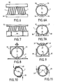
- FIGS. 6-6A, 7-7A and 8 to 13 give some examples of practical, nonexhaussive arrangements and it is possible to bring other variant configurations without departing from the scope of the present invention. Each case includes the shear prestressing means described.
- the supports are generally metallic, in particular for severe applications (heat, corrosion), but can be made of any other material deemed appropriate.
- the cable can be made of a synthetic material such as "Nylon”, or even metallic, coated with a protective substance.
- the cable is "clamped between the bars (2), preferably by mechanical means, and the stiffeners (3) may include grooved arrangements, in order to guide the cable, or be covered with any suitable material making it possible to avoid problems. of contact between cable and stiffeners.
- stiffeners (3) can form an integral part of a bar (2) or be attached by screw or any other means thereon.
- the assembly can be made by any process deemed interesting and, among other things, in mechanically welded construction, by foundry, forging, etc.
- each assembly (bar-stiffeners) (2A-3A) constitutes a gutter and is arranged opposite another bar-stiffener assembly in the form of gutters ( 2A-3A).
- the stiffeners (3B) are part of a set (bar-stiffeners) (2B-3B) and opposite this set is arranged a bar-stiffeners assembly (2C-3C) of curved shape matching the loops of the cable (1) wound in a helix.
- a set (bar-stiffeners) (2D-3D) of straight section in "U” covers the loops of the cable (1) retained vis-à-vis by a bar (2 ) fixed on a simple plate (5).
- a set (bar-stiffeners) (2F-3F) in the shape of a policeman's hat.
- the stiffeners constitute stiffening wings on either side of the bar in question and are arranged outside the loops of the cable (1).
- a single stiffening wing constitutes the stiffener (3G) associated with each bar (2G).
- a single stiffening wing associated with a bar or with each bar is envisaged inside the loops of the cable.
- two stiffening wings constitute the stiffeners (3H) on either side of each bar. (2H) and the stiffeners are also located inside the loops of the cable (1) thus bringing progressive contact.
- Figures 12 and 13 show the shear prestressing means according to two possible variants.
- the shear prestressing means are made adjustable (4B) (variation D), and are constituted by a rotating device, not to the left, not to the right.
Abstract
Description
On connaît déjà depuis longtemps les supports amortisseurs à câble métallique dont le principe consiste à utiliser un câble en acier, enroulé en hélice et retenu par des barrettes (voir les figures 1, lA, lB des dessins annexés).Metal cable damping supports have already been known for a long time, the principle of which is to use a steel cable, wound in a helix and retained by bars (see FIGS. 1, 1A, 1B of the accompanying drawings).
Les principaux avantages de ces supports résident dans : une construction entièrement métallique ; une bonne isolation combinée contre les chocs et les vibrations ; une efficacité omnidirectionnelle large ; une fourchette de température de service ; une excellente résistance à la corrosion ; et une très grande robustesse.The main advantages of these supports lie in: an all-metal construction; good combined insulation against shock and vibration; broad omni-directional efficiency; a serving temperature range; excellent resistance to corrosion; and a very strong robustness.
Dans la description qui suit, ce type de support amortisseur connu sera désigné par le terme "support classique".In the following description, this type of known damping support will be designated by the term "conventional support".
La présente invention se rapporte à un support amortisseur pour lequel on utilisera plus loin le vocable "support amélioré". Elle vise en effet à améliorer, dans une proportion importante, les performances chocs-vibrations des supports amortisseurs à câble métallique classiques tout en en augmentant la charge admissible.The present invention relates to a damping support for which the term "improved support" will be used later. It aims in fact to improve, in a significant proportion, the shock-vibration performance of shock absorber supports with conventional metal cable while increasing the admissible load.
Les charges unitaires des supports classiques s'étendent de quelques grammes à quelques tonnes, ce qui est insuffisant pour les utiliser dans de nombreuses applications, compte tenu de l'encombrement important nécessité par un grand nombre de supports. Par ailleurs, il est difficile de réaliser économiquement des supports pour charge importante, toujours selon le type classique, en raison notamment de ce qu'un câble de grand diamètre est difficile à enrouler.The unit loads of conventional supports range from a few grams to a few tonnes, which is insufficient to use them in many applications, given the large size required by a large number of supports. Furthermore, it is difficult to economically produce supports for high load, always according to the conventional type, due in particular to the fact that a cable of large diameter is difficult to wind.
En revanche, dans le cadre de la présente invention, les supports peuvent accepter de très fortes charges et sont réalisables en conservant un volume identique à celui des supports classiques et en en conservant les avantages inhérents.On the other hand, in the context of the present invention, the supports can accept very high loads and are achievable by keeping a volume identical to that of conventional supports and by retaining the inherent advantages.
En outre, dans de nombreux cas, les suspensions à câble sont destinées à protéger des chocs des matériels fragiles installés dans des containers spéciaux ; les gabarits disponibles rendent souvent aigus les problèmes d'encombrement et la déflexion dynamique des suspensions doit être la plus réduite possible eu égard à l'accélération résiduelle admissible sur le spécimen, pour absorber un choc donné.In addition, in many cases, cable suspensions are intended to protect against impact of fragile materials installed in special containers; available templates often make problems acute dimensions and the dynamic deflection of the suspensions must be as small as possible having regard to the admissible residual acceleration on the specimen, to absorb a given shock.
La présente invention permet de diminuer considérablement la course nécessaire, en augmentant la capacité d'absorption d'énergie de la suspension, pour un résiduel inchangé, et même souvent plus faible.The present invention makes it possible to considerably reduce the necessary stroke, by increasing the energy absorption capacity of the suspension, for an unchanged, and often even lower, residual.
De plus, en vibrations, la fréquence propre du système est variable, selon la sévérité de la sollicitation, et la non linéarité introduite par le raidisseur permet, dans certains cas, d'éviter des amplitudes trop élevées à la résonance (voir figure 11 par exemple).In addition, in vibrations, the natural frequency of the system is variable, depending on the severity of the stress, and the non-linearity introduced by the stiffener makes it possible, in certain cases, to avoid excessively high amplitudes at resonance (see FIG. 11 by example).
Enfin, dans de nombreux cas, les déplacements dynamiques des plots antivibratiles doivent être réduits en cas de surcharge accidentelle ou non et les supports améliorés selon l'invention peuvent remplir l'office supplémentaire de butée progressive par rapport aux supports classiques.Finally, in many cases, the dynamic displacements of the antivibration pads must be reduced in the event of accidental overload or not and the improved supports according to the invention can fill the additional office of progressive abutment compared to conventional supports.
La présente invention consiste en un câble métallique ou non, de composition et géométrie variables en fonction des caractéristiques de raideur et d'amortissement requises, enroulé en hélice et retenu par des barrettes comportant des moyens raidisseurs ainsi que des moyens de précontrainte en cisaillement.The present invention consists of a metallic cable or not, of variable composition and geometry as a function of the required stiffness and damping characteristics, wound in a helix and retained by bars comprising stiffening means as well as prestressing means in shear.
D'autres caractéristiques et avantages de la présente invention ressortiront de la description qui va suivre faite en regard des dessins annexés sur lesquels :
- - les figures 1, lA et 1B schématisent un support à câble métallique classique et représentent, respectivement, le support soumis à des sollicitations en roulis, compression à plat et cisaillement (les traits pleins fins symbolisent le câble dans sa position initiale et les pointillés montrent la déformation de la boucle sous l'effet de la charge ; pour la clarté de l'exposé, les sollicitations ont été volontairement décomposées en trois sollicitations principales mais il est clair que la réalité est toujours une combinaison d'entre elles) ;
- - les figures 2, 2A et 2B sont en correspondance comparative avec les figures 1, 1A et lB et schématisent un support à câble amélioré selon la présente invention ;
- - les figures 3, 4 et 5 représentent trois cas typiques d'amélioration possible de caractéristiques et chaque figure montre une courbe force-déflexion, la force (F) étant portée en ordonnée et le déplacement (8) en abscisse (les symboles (F) et (δ) sont également indiqués sur les figures 1, lA, 1B et 2, 2A, 2B) ;
- - les figures 6 et 6A sont des vues, respectivement en élévation latérale et en bout, d'une forme de réalisation d'un support amélioré ;
- - les figures 7 et 7A sont des vues, respectivement en élévation latérale et en bout, d'une autre forme de réalisation d'un support amélioré ;
- - la figure 8 est une vue en bout d'une autre forme de réalisation d'un support amélioré ;
- - la figure 9 est une vue en coupe d'encore une autre variante de support amélioré ;
- - les figures 10 et il sont des vues en bout de deux autres variantes de support amélioré ;
- - les figures 12 et 13 sont des vues en élévation latérale schématique et en coupe partielle de deux variantes de moyens de précontrainte de cisaillement.
- - la figure 14 est une vue en élévation schématique d'une variante de disposition de supports améliorés.
- - Figures 1, 1A and 1B show a conventional metal cable support and represent, respectively, the support subjected to roll stresses, flat compression and shear (the solid lines show the cable in its initial position and the dotted lines show the deformation of the loop under the effect of the load; for the sake of clarity, the stresses have been deliberately broken down into three main stresses, but it is clear that reality is always a combination of them);
- - Figures 2, 2A and 2B are in comparative correspondence with Figures 1, 1A and 1B and show schematically an improved cable support according to the present invention;
- - Figures 3, 4 and 5 represent three typical cases of possible improvement of characteristics and each figure shows a force-deflection curve, the force (F) being plotted on the ordinate and the displacement (8) on the abscissa (the symbols (F ) and (δ) are also indicated in FIGS. 1, 1A, 1B and 2, 2A, 2B);
- - Figures 6 and 6A are views, respectively in side elevation and end, of an embodiment of an improved support;
- - Figures 7 and 7A are views, respectively in side elevation and end, of another embodiment of an improved support;
- - Figure 8 is an end view of another embodiment of an improved support;
- - Figure 9 is a sectional view of yet another variant of improved support;
- - Figures 10 and there are end views of two other variants of improved support;
- - Figures 12 and 13 are schematic side elevational views in partial section of two variants of shear prestressing means.
- - Figure 14 is a schematic elevational view of an alternative arrangement of improved supports.
La présente invention a pour objet un support antivibratile/antichocs à élément élastique, lequel support est amélioré par un système de moyens raidisseurs et de moyens de précontrainte, longitudinale, destiné à réaliser la protection active ou passive d'un matériel contre les chocs et les vibrations.The subject of the present invention is an anti-vibration / shock-absorbing support with elastic element, which support is improved by a system of stiffening means and prestressing means, longitudinal, intended to provide active or passive protection of a material against shocks and vibrations.
L'élément élastique (1) est un câble, de préférence métallique, comportant un nombre variable de fils et de torons selon les caractéristiques d'amortissement recherchées. Ce câble est enroulé en hélice et retenu par des barrettes (2).The elastic element (1) is a cable, preferably metallic, comprising a variable number of wires and strands according to the desired damping characteristics. This cable is wound in a helix and retained by bars (2).
Au moins l'une des barrettes comporte des moyens raidisseurs (3) permettant d'augmenter les caractéristiques de raideur et/ou de remplir un rôle de butée progressive selon un ou plusieurs axes.At least one of the bars comprises stiffening means (3) making it possible to increase the stiffness characteristics and / or to fulfill a role of progressive stop along one or more axes.
Les moyens de précontrainte en cisaillement (4) sont inclus entre deux demi-barrettes (2A-2B) et peuvent être variables par écartement de ces demi-barrettes afin de raidir le support selon cet axe et d'éviter tout phénomène d'instabilité.The shear prestressing means (4) are included between two half-bars (2A-2B) and can be variable by spacing these half-bars in order to stiffen the support along this axis and to avoid any phenomenon of instability.
Les perfectionnements apportés dans le cadre de la présente invention "raidissent" sensiblement le support anti-vibratile/antichocs, et ceci dans toutes les directions.The improvements made in the context of the present invention substantially "stiffen" the anti-vibration / shock-absorbing support, and this in all directions.
Cette amélioration de caractéristiques, confirmée par le calcul et l'expérimentation, est illustrée sur les figures 2, 2A, 2B.This improvement in characteristics, confirmed by calculation and experimentation, is illustrated in Figures 2, 2A, 2B.
Si l'on se reporte, à présent, aux figures 3 à 5, le trait plein (I) représente la courbe obtenue avec un support à câble classique et les traits pointillés référencés (II) (III) ou (IV) représentent les courbes obtenues avec un support amélioré.If we now refer to Figures 3 to 5, the solid line (I) represents the curve obtained with a conventional cable support and the dotted lines referenced (II) (III) or (IV) represent the curves obtained with improved support.
La figure 3 est un exemple illustrant la possibilité d'amélioration de l'énergie potentielle emmaga- sinable dans le support, laquelle énergie est égale à l'aire entre la courbe et l'axe des abscisses. La force en ordonnée, est celle appliquée au matériel protégé. On voit donc que pour un point de fonctionnement (P), indiqué sur la figure, la capacité énergétique du support amélioré est presque double de celle du support classique. En d'autres termes, pour une énergie donnée, le support amélioré demande une déflexion dynamique plus faible, économisant, d'autant, l'espace disponible à prévoir.FIG. 3 is an example illustrating the possibility of improving the potential energy that can be stored in the support, which energy is equal to the area between the curve and the abscissa axis. The ordinate force is that applied to the protected material. It can therefore be seen that for an operating point (P), indicated in the figure, the energy capacity of the improved support is almost double that of the conventional support. In other words, for a given energy, the improved support requires a lower dynamic deflection, thereby saving the available space to be provided.
La figure 4 illustre l'utilisation de la présente invention en butée progressive. Le point de fonctionnement (P) indique la charge statique appliquée au support. Dans le cas du support classique (courbe I), on voit que l'application d'un effort dynamique accidentel important entraîne une déflexion dynamique beaucoup plus importante que dans le cas du support amélioré (courbe II). Cette particularité est très intéressante pour toute suspension devant présenter des débattements limités (moteurs reliés à un accouplement très rigide et à des tuyauteries, comme c'est le cas pour les moteurs de propulsion marine par exemple).FIG. 4 illustrates the use of the present invention in progressive abutment. The operating point (P) indicates the static load applied to the support. In the case of the conventional support (curve I), it can be seen that the application of a large accidental dynamic force causes a much greater dynamic deflection than in the case of the improved support (curve II). This feature is very interesting for any suspension that must have limited travel (motors connected to a very rigid coupling and to pipes, as is the case for marine propulsion engines for example).
La figure 5 illustre les effets d'une précontrainte en cisaillement. La courbe (I) représente le support classique, les courbes (II), (III), et (IV) représentent le support amélioré avec une précontrainte de plus en plus importante, respectivement. Ce système de précontrainte appartient au cadre de la présente invention en ce sens que les raidisseurs améliorant les caractéristiques en compression et roulis, il est indispensable de les améliorer également en cisaillement, afin d'éviter tout phénomène d'instabilité qui pourrait être engendré par des disproportions entre les raideurs selon les trois axes principaux.Figure 5 illustrates the effects of prestressing in shear. Curve (I) represents the conventional support, curves (II), (III), and (IV) represent the improved support with an increasing prestress, respectively. This prestressing system belongs to the framework of the present invention in the sense that the stiffeners improving the characteristics in compression and roll, it is essential to also improve them in shear, in order to avoid any phenomenon of instability which could be generated by disproportions between the stiffnesses according to the three main axes.
Il est clair, que selon les cas, on peut avoir un support amélioré soit par raidisseurs, soit par précontrainte en cisaillement, soit par une combinaison des deux, sans sortir du cadre de la présente invention, celle-ci ayant pour but général la rigidification du support classique selon un, deux ou trois axes. Entre autre, un support basse fréquence peut être réalisé par une précontrainte en cisaillement uniquement afin de préserver la stabilité latérale en diminuant la raideur verticale.It is clear that, depending on the case, it is possible to have an improved support either by stiffeners, or by prestressing in shear, or by a combination of the two, without departing from the scope of the present invention, the latter having the general aim of stiffening classic support along one, two or three axes. Among other things, a low frequency support can be achieved by shear preload only in order to preserve lateral stability by reducing the vertical stiffness.
Les trois cas types précédemment décrits ne sont pas exhaussifs et la présente invention pourra trouver un intérêt particulier selon chaque cas.The three standard cases described above are not exhaustive and the present invention may find particular interest in each case.
Les figures 6-6A, 7-7A et 8 à 13 donnent quelques exemples de dispositions pratiques, non exhaussifs et l'on pourra apporter d'autres variantes de configurations sans sortir du cadre de la présente invention. Chaque cas inclut les moyens de précontrainte en cisaillement décrits.FIGS. 6-6A, 7-7A and 8 to 13 give some examples of practical, nonexhaussive arrangements and it is possible to bring other variant configurations without departing from the scope of the present invention. Each case includes the shear prestressing means described.
Les supports sont en général métalliques, en particulier pour les applications sévères (chaleur, corrosion), mais peuvent être réalisés en tout autre matériau jugé opportun. Entre autres, le câble peut être en une matière synthétique telle le "Nylon", ou même métallique, enrobé d'une substance protectrice. Le cable est "serré entre les barrettes (2), par des moyens mécaniques préférentiellement, et les raidisseurs (3) peuvent comporter des dispositions à gorges, afin de guider le câble, ou être recouverts de tout matériau adéquat permettant d'éviter des problèmes de contact entre câble et raidisseurs.The supports are generally metallic, in particular for severe applications (heat, corrosion), but can be made of any other material deemed appropriate. Among other things, the cable can be made of a synthetic material such as "Nylon", or even metallic, coated with a protective substance. The cable is "clamped between the bars (2), preferably by mechanical means, and the stiffeners (3) may include grooved arrangements, in order to guide the cable, or be covered with any suitable material making it possible to avoid problems. of contact between cable and stiffeners.
Il est clair que les raidisseurs (3) peuvent former partie intégrante d'une barrette (2) ou être rapportés par vis ou tout autre moyen sur celle-ci.It is clear that the stiffeners (3) can form an integral part of a bar (2) or be attached by screw or any other means thereon.
L'ensemble peut être réalisé par tout procédé jugé intéressant et, entre autres, en construction mécano- soudée, par fonderie, forgeage, etc.The assembly can be made by any process deemed interesting and, among other things, in mechanically welded construction, by foundry, forging, etc.
Dans la forme de réalisation représentée aux figures 6 et 6A, chaque ensemble (barrette-raidisseurs) (2A-3A) constitue une gouttière et est disposé en vis-à-vis d'un autre ensemble barrette-raidisseurs en forme de gouttières également (2A-3A).In the embodiment shown in FIGS. 6 and 6A, each assembly (bar-stiffeners) (2A-3A) constitutes a gutter and is arranged opposite another bar-stiffener assembly in the form of gutters ( 2A-3A).
Dans la forme de réalisation représentée aux figures 7 et 7A, les raidisseurs (3B) font partie d'un ensemble (barrette-raidisseurs) (2B-3B) et en vis-à-vis de cet ensemble est disposé un ensemble barrette-raidisseurs (2C-3C) de forme courbe épousant les boucles du câble (1) enroulé en hélice.In the embodiment shown in Figures 7 and 7A, the stiffeners (3B) are part of a set (bar-stiffeners) (2B-3B) and opposite this set is arranged a bar-stiffeners assembly (2C-3C) of curved shape matching the loops of the cable (1) wound in a helix.
Dans la forme de réalisation représentée à la figure 8, un ensemble (barrette-raidisseurs) (2D-3D) de section droite en "U" coiffe les boucles du câble (1) retenues en vis-à-vis par une barrette (2) fixée sur une simple plaque (5).In the embodiment shown in Figure 8, a set (bar-stiffeners) (2D-3D) of straight section in "U" covers the loops of the cable (1) retained vis-à-vis by a bar (2 ) fixed on a simple plate (5).
Dans la forme de réalisation de la figure 9, un ensemble (barrette-raidisseurs) (2E-3E) également de section droite en "U", constitue un berceau pour les boucles du câble (1). En vis-à-vis, est disposé un ensemble (barrette-raidisseurs) (2F-3F) en forme de chapeau de gendarme.In the embodiment of Figure 9, a set (bar-stiffeners) (2E-3E) also of cross section in "U", constitutes a cradle for the cable loops (1). Opposite, there is a set (bar-stiffeners) (2F-3F) in the shape of a policeman's hat.
Dans chacun des ensembles barrette-raidisseurs exposés ci-dessus, les raidisseurs constituent des ailes de raidissement de part et d'autre de la barrette considérée et sont disposés à l'extérieur des boucles du câble (1).In each of the bar-stiffener assemblies described above, the stiffeners constitute stiffening wings on either side of the bar in question and are arranged outside the loops of the cable (1).
Dans la forme de réalisation de la figure 10, une seule aile de raidissement constitue le raidisseur (3G) associé à chaque barrette (2G).In the embodiment of Figure 10, a single stiffening wing constitutes the stiffener (3G) associated with each bar (2G).
Selon une variante non représentée, une seule aile de raidissement associée à une barrette ou à chaque barrette est envisagée à l'intérieur des boucles du câble.According to a variant not shown, a single stiffening wing associated with a bar or with each bar is envisaged inside the loops of the cable.
Dans la variante de la figure 11, deux ailes de raidissement constituent les raidisseurs (3H) de part et d'autre de chaque barrette . (2H) et les raidisseurs se trouvent également à l'intérieur des boucles du câble (1) amenant ainsi un contact progressif.In the variant of FIG. 11, two stiffening wings constitute the stiffeners (3H) on either side of each bar. (2H) and the stiffeners are also located inside the loops of the cable (1) thus bringing progressive contact.
Les figures 12 et 13 montrent les moyens de précontrainte en cisaillement selon deux variantes possibles.Figures 12 and 13 show the shear prestressing means according to two possible variants.
Sur la figure 12, les moyens de précontrainte en cisaillement sont déterminés par le constructeur au moyen de cales (4A).In FIG. 12, the means of prestressing in shear are determined by the manufacturer by means of shims (4A).
Dans la variante de la figure 13, les moyens de précontrainte en cisaillement sont rendus réglables (4B) (variation D), et sont constitués par un dispositif tournant, pas à gauche, pas à droite.In the variant of FIG. 13, the shear prestressing means are made adjustable (4B) (variation D), and are constituted by a rotating device, not to the left, not to the right.
Bien entendu, ces deux exemples de réalisation ne sont représentés qu'à titre indicatif.Of course, these two embodiments are only shown for information.
Bien que les explications précédentes se soient limitées, pour des raisons de clarté, à des cas de charge suivant trois axe trirectangulaires, toute possibilité combinée, ou toute inclinaison des supports selon un, deux ou trois plans sont possibles et ne s'écartent pas de l'amélioration proposée. On peut entre autre réaliser un support avec une précontrainte en roulis et une butée inférieure de fin de course. (Ce système présente l'avantage d'un montage plus simple qu'une configuration à 45° avec les mêmes avantages, soit course importante, soit butée progressive et raideur latérale très importante).Although the preceding explanations have been limited, for reasons of clarity, to cases of load along three trirectangular axes, any combined possibility, or any inclination of the supports according to one, two or three planes are possible and do not deviate from the proposed improvement. Among other things, it is possible to produce a support with a roll preload and a lower end of travel stop. (This system has the advantage of a simpler mounting than a 45 ° configuration with the same advantages, either large stroke, or progressive stop and very significant lateral stiffness).
Il est clair que la variation de la cote "x" (figure 14) modifie les performances du système. Dans ce cas, les raidisseurs permettent de ne pas "blesser" le câble. Dans cette disposition, chaque raidisseur (3K) extérieur au câble et chaque raidiseur (3L) intérieur au câble se trouvent être tête-bêche par rapport à la barrette (2K).It is clear that the variation of the dimension "x" (figure 14) modifies the performances of the system. In this case, the stiffeners do not "hurt" the cable. In this arrangement, each stiffener (3K) outside the cable and each stiffener (3L) inside the cable happen to be head to tail relative to the bar (2K).
D'une manière générale, il va de soi que la présente invention n'a été décrite et représentée qu'à titre d'exemple préférentiel et que l'on pourra apporter des équivalences dans ses éléments constitutifs sans sortir de son cadre.In general, it goes without saying that the present invention has only been described and shown as a preferred example and that it will be possible to provide equivalences in its constituent elements without departing from its scope.
Claims (12)
Priority Applications (1)
| Application Number | Priority Date | Filing Date | Title |
|---|---|---|---|
| AT82400274T ATE18594T1 (en) | 1981-02-17 | 1982-02-16 | VIBRATION AND SHOCK ABSORBING BEARING. |
Applications Claiming Priority (2)
| Application Number | Priority Date | Filing Date | Title |
|---|---|---|---|
| FR8103064 | 1981-02-17 | ||
| FR8103064A FR2500097B1 (en) | 1981-02-17 | 1981-02-17 | ANTI-VIBRATION SHOCK ABSORBER, SHOCK ABSORBER |
Publications (2)
| Publication Number | Publication Date |
|---|---|
| EP0059143A1 true EP0059143A1 (en) | 1982-09-01 |
| EP0059143B1 EP0059143B1 (en) | 1986-03-12 |
Family
ID=9255286
Family Applications (1)
| Application Number | Title | Priority Date | Filing Date |
|---|---|---|---|
| EP82400274A Expired EP0059143B1 (en) | 1981-02-17 | 1982-02-16 | Vibration and shock absorbing mounting |
Country Status (4)
| Country | Link |
|---|---|
| EP (1) | EP0059143B1 (en) |
| AT (1) | ATE18594T1 (en) |
| DE (1) | DE3269770D1 (en) |
| FR (1) | FR2500097B1 (en) |
Cited By (8)
| Publication number | Priority date | Publication date | Assignee | Title |
|---|---|---|---|---|
| US4783038A (en) * | 1987-07-07 | 1988-11-08 | Aeroflex International Incorporated | Isolator apparatus |
| US5277394A (en) * | 1992-11-02 | 1994-01-11 | Arlo Slemmer | Coaxial isolator device |
| WO2006046103A1 (en) * | 2004-10-26 | 2006-05-04 | Somfy Sas | Anti-vibration bracket for tubular motor |
| US7144001B2 (en) * | 2002-03-14 | 2006-12-05 | Olav Kaarstein | Device and a system for damping vibrations, impact and shock |
| WO2009113868A1 (en) | 2008-03-11 | 2009-09-17 | Techni As | Shock and vibration damper |
| CN102865325A (en) * | 2011-07-05 | 2013-01-09 | 上海微电子装备有限公司 | Vibration damping device, vibration damping equipment and vibration damping system |
| DE112010000809T5 (en) | 2009-01-21 | 2013-06-20 | Rafael Advanced Defense Systems Ltd. | Damping suspension with the possibility of lifting for an additional reinforcement system |
| US8783518B2 (en) | 2008-12-29 | 2014-07-22 | Otic Pharma Ltd. | Multiple-metered self-cleaning dispenser |
Families Citing this family (2)
| Publication number | Priority date | Publication date | Assignee | Title |
|---|---|---|---|---|
| DE4307031C2 (en) * | 1993-03-05 | 1995-04-20 | Gerhard Maas | Vibration damper |
| GB0308732D0 (en) * | 2003-04-15 | 2003-05-21 | Axcess Ltd | Absorption enhancers |
Citations (13)
| Publication number | Priority date | Publication date | Assignee | Title |
|---|---|---|---|---|
| DE541416C (en) * | 1930-08-29 | 1932-01-12 | Albrecht Steinbach Dr Ing | Shock-reducing pad |
| FR782906A (en) * | 1934-03-09 | 1935-07-05 | Mounting of alternative machines on the supports | |
| US2154586A (en) * | 1937-07-31 | 1939-04-18 | Stern Nathan Solly | Shock absorbing device |
| US2525730A (en) * | 1949-01-25 | 1950-10-10 | Carnegie Illinois Steel Corp | Resilient cushion utilizing sideloaded helical spring |
| GB878776A (en) * | 1958-06-28 | 1961-10-04 | Rose Brothers Ltd | Improvements in or relating to low stiffness spring units |
| US3007660A (en) * | 1958-10-27 | 1961-11-07 | Rosan Eng Corp | Shock isolating support |
| FR1372335A (en) * | 1962-10-25 | 1964-09-11 | Aeroflex Lab Inc | Vibration damper and load support device |
| FR1460785A (en) * | 1965-10-14 | 1966-01-07 | Process for manufacturing shock and vibration isolators or dampers and devices thus obtained | |
| FR1560072A (en) * | 1967-03-30 | 1969-03-14 | ||
| FR1569208A (en) * | 1967-05-26 | 1969-05-30 | ||
| FR2033193A1 (en) * | 1968-09-30 | 1970-12-04 | Camossi Carlo | |
| FR2189660A1 (en) * | 1972-06-21 | 1974-01-25 | Camossi Carlo | |
| FR2359324A1 (en) * | 1976-07-22 | 1978-02-17 | Aeroflex Lab Inc | VIBRATION ISOLATOR AND METHOD OF MANUFACTURING |
-
1981
- 1981-02-17 FR FR8103064A patent/FR2500097B1/en not_active Expired
-
1982
- 1982-02-16 EP EP82400274A patent/EP0059143B1/en not_active Expired
- 1982-02-16 AT AT82400274T patent/ATE18594T1/en not_active IP Right Cessation
- 1982-02-16 DE DE8282400274T patent/DE3269770D1/en not_active Expired
Patent Citations (13)
| Publication number | Priority date | Publication date | Assignee | Title |
|---|---|---|---|---|
| DE541416C (en) * | 1930-08-29 | 1932-01-12 | Albrecht Steinbach Dr Ing | Shock-reducing pad |
| FR782906A (en) * | 1934-03-09 | 1935-07-05 | Mounting of alternative machines on the supports | |
| US2154586A (en) * | 1937-07-31 | 1939-04-18 | Stern Nathan Solly | Shock absorbing device |
| US2525730A (en) * | 1949-01-25 | 1950-10-10 | Carnegie Illinois Steel Corp | Resilient cushion utilizing sideloaded helical spring |
| GB878776A (en) * | 1958-06-28 | 1961-10-04 | Rose Brothers Ltd | Improvements in or relating to low stiffness spring units |
| US3007660A (en) * | 1958-10-27 | 1961-11-07 | Rosan Eng Corp | Shock isolating support |
| FR1372335A (en) * | 1962-10-25 | 1964-09-11 | Aeroflex Lab Inc | Vibration damper and load support device |
| FR1460785A (en) * | 1965-10-14 | 1966-01-07 | Process for manufacturing shock and vibration isolators or dampers and devices thus obtained | |
| FR1560072A (en) * | 1967-03-30 | 1969-03-14 | ||
| FR1569208A (en) * | 1967-05-26 | 1969-05-30 | ||
| FR2033193A1 (en) * | 1968-09-30 | 1970-12-04 | Camossi Carlo | |
| FR2189660A1 (en) * | 1972-06-21 | 1974-01-25 | Camossi Carlo | |
| FR2359324A1 (en) * | 1976-07-22 | 1978-02-17 | Aeroflex Lab Inc | VIBRATION ISOLATOR AND METHOD OF MANUFACTURING |
Cited By (14)
| Publication number | Priority date | Publication date | Assignee | Title |
|---|---|---|---|---|
| GB2206667A (en) * | 1987-07-07 | 1989-01-11 | Aeroflex Int Inc | Isolation apparatus |
| FR2617933A1 (en) * | 1987-07-07 | 1989-01-13 | Aeroflex Int Inc | ANTI-VIBRATORY AND ANTI-SHOCK ISOLATION DEVICE |
| DE3737934A1 (en) * | 1987-07-07 | 1989-01-19 | Aeroflex Int Inc | VIBRATION INSULATOR |
| GB2206667B (en) * | 1987-07-07 | 1991-07-10 | Aeroflex Int Inc | Improved isolation apparatus |
| US4783038A (en) * | 1987-07-07 | 1988-11-08 | Aeroflex International Incorporated | Isolator apparatus |
| US5277394A (en) * | 1992-11-02 | 1994-01-11 | Arlo Slemmer | Coaxial isolator device |
| US7144001B2 (en) * | 2002-03-14 | 2006-12-05 | Olav Kaarstein | Device and a system for damping vibrations, impact and shock |
| WO2006046103A1 (en) * | 2004-10-26 | 2006-05-04 | Somfy Sas | Anti-vibration bracket for tubular motor |
| WO2009113868A1 (en) | 2008-03-11 | 2009-09-17 | Techni As | Shock and vibration damper |
| EP2265841A4 (en) * | 2008-03-11 | 2017-12-13 | Techni AS | Shock and vibration damper |
| US8783518B2 (en) | 2008-12-29 | 2014-07-22 | Otic Pharma Ltd. | Multiple-metered self-cleaning dispenser |
| DE112010000809T5 (en) | 2009-01-21 | 2013-06-20 | Rafael Advanced Defense Systems Ltd. | Damping suspension with the possibility of lifting for an additional reinforcement system |
| US8640593B2 (en) | 2009-01-21 | 2014-02-04 | Rafael Advanced Defense Systems Ltd. | Damping suspension with an up-lift capability for an add-on armor system |
| CN102865325A (en) * | 2011-07-05 | 2013-01-09 | 上海微电子装备有限公司 | Vibration damping device, vibration damping equipment and vibration damping system |
Also Published As
| Publication number | Publication date |
|---|---|
| ATE18594T1 (en) | 1986-03-15 |
| DE3269770D1 (en) | 1986-04-17 |
| EP0059143B1 (en) | 1986-03-12 |
| FR2500097B1 (en) | 1986-04-04 |
| FR2500097A1 (en) | 1982-08-20 |
Similar Documents
| Publication | Publication Date | Title |
|---|---|---|
| EP0059143B1 (en) | Vibration and shock absorbing mounting | |
| CA2658317C (en) | Aircraft doorway | |
| EP1192404B1 (en) | Wall protecting device | |
| EP2707279B1 (en) | Vessel of the type comprising at least one shaft for receiving at least one missile-launching container | |
| EP3562714B1 (en) | Impact absorbing system for motor vehicle | |
| EP3738839B1 (en) | Motor vehicle shock absorbing system | |
| EP0666432A1 (en) | Shock- and vibration-damping stud | |
| EP2415117B1 (en) | Radio antenna comprising improved rigidifying means | |
| EP2246221B1 (en) | Go-kart with elastic shock absorbing means, corresponding device | |
| EP0429455B1 (en) | Shock absorber device | |
| EP1580096A1 (en) | Vehicle frame comprising an antivibration device | |
| FR2849416A1 (en) | ENERGY ABSORBING HOUSING FOR MOTOR VEHICLE BUMPER | |
| FR3021625A1 (en) | FLEXIBLE CONNECTION BETWEEN THE FLOOR STRUCTURE AND THE HULL STRUCTURE OF AN AIRCRAFT. | |
| FR2905925A1 (en) | Frontal impact energy absorbing device for motor vehicle, has foam with energy absorbing properties, housed in casing, fixation plate fixing device on part of vehicle, and deformation element with reinforcements, formed by casing edges | |
| FR2795793A1 (en) | Energy absorbing linkage for gas turbine mounting in aircraft has female casing defining chamber traversed by rod | |
| EP3985277B1 (en) | Improved damping device for spacecraft and method for manufacturing the damping device | |
| WO2019229319A1 (en) | Vibrational energy recovery system | |
| FR2791626A1 (en) | Shock absorbing chassis beam for motor vehicle has interior boxes containing pressurised gas to control deformation of chassis structure | |
| FR2699630A1 (en) | Shock absorber and vibration damper for general suspension | |
| FR2986843A1 (en) | Structural connection device for transmitting tensile or compressive stress between engine and mast reactor of aircraft, has connection ring connecting beams for ensuring filtering of vibrations generated by structure elements | |
| FR2776254A1 (en) | Arrangements, in vehicle, for absorbing kinetic energy of shock loads e.g. due to a collision | |
| FR3132501A1 (en) | Device and method for damping and protection during a sliding phase for a part of an aircraft. | |
| FR2810602A1 (en) | Bumper bar, for vehicle, is made of series of segments, held in line by return mechanism, which is designed to return segments against fixed faces, after displacement under externally applied loads. | |
| EP1700749B1 (en) | Docking buffer | |
| EP3798455A1 (en) | Thermal uncoupling device |
Legal Events
| Date | Code | Title | Description |
|---|---|---|---|
| PUAI | Public reference made under article 153(3) epc to a published international application that has entered the european phase |
Free format text: ORIGINAL CODE: 0009012 |
|
| AK | Designated contracting states |
Designated state(s): AT BE CH DE FR GB IT LU NL SE |
|
| ITCL | It: translation for ep claims filed |
Representative=s name: BARZANO' E ZANARDO ROMA S.P.A. |
|
| 17P | Request for examination filed |
Effective date: 19830204 |
|
| GRAA | (expected) grant |
Free format text: ORIGINAL CODE: 0009210 |
|
| ITF | It: translation for a ep patent filed |
Owner name: BARZANO' E ZANARDO ROMA S.P.A. |
|
| AK | Designated contracting states |
Kind code of ref document: B1 Designated state(s): AT BE CH DE FR GB IT LI LU NL SE |
|
| REF | Corresponds to: |
Ref document number: 18594 Country of ref document: AT Date of ref document: 19860315 Kind code of ref document: T |
|
| REF | Corresponds to: |
Ref document number: 3269770 Country of ref document: DE Date of ref document: 19860417 |
|
| PLBE | No opposition filed within time limit |
Free format text: ORIGINAL CODE: 0009261 |
|
| STAA | Information on the status of an ep patent application or granted ep patent |
Free format text: STATUS: NO OPPOSITION FILED WITHIN TIME LIMIT |
|
| 26N | No opposition filed | ||
| PGFP | Annual fee paid to national office [announced via postgrant information from national office to epo] |
Ref country code: FR Payment date: 19911227 Year of fee payment: 11 |
|
| PGFP | Annual fee paid to national office [announced via postgrant information from national office to epo] |
Ref country code: AT Payment date: 19920122 Year of fee payment: 11 |
|
| PGFP | Annual fee paid to national office [announced via postgrant information from national office to epo] |
Ref country code: GB Payment date: 19920203 Year of fee payment: 11 |
|
| PGFP | Annual fee paid to national office [announced via postgrant information from national office to epo] |
Ref country code: CH Payment date: 19920212 Year of fee payment: 11 |
|
| PGFP | Annual fee paid to national office [announced via postgrant information from national office to epo] |
Ref country code: LU Payment date: 19920219 Year of fee payment: 11 |
|
| PGFP | Annual fee paid to national office [announced via postgrant information from national office to epo] |
Ref country code: SE Payment date: 19920224 Year of fee payment: 11 |
|
| ITTA | It: last paid annual fee | ||
| PGFP | Annual fee paid to national office [announced via postgrant information from national office to epo] |
Ref country code: NL Payment date: 19920229 Year of fee payment: 11 |
|
| PGFP | Annual fee paid to national office [announced via postgrant information from national office to epo] |
Ref country code: BE Payment date: 19920312 Year of fee payment: 11 |
|
| PGFP | Annual fee paid to national office [announced via postgrant information from national office to epo] |
Ref country code: DE Payment date: 19920413 Year of fee payment: 11 |
|
| EPTA | Lu: last paid annual fee | ||
| PG25 | Lapsed in a contracting state [announced via postgrant information from national office to epo] |
Ref country code: LU Free format text: LAPSE BECAUSE OF NON-PAYMENT OF DUE FEES Effective date: 19930216 Ref country code: GB Effective date: 19930216 Ref country code: AT Effective date: 19930216 |
|
| PG25 | Lapsed in a contracting state [announced via postgrant information from national office to epo] |
Ref country code: SE Effective date: 19930217 |
|
| PG25 | Lapsed in a contracting state [announced via postgrant information from national office to epo] |
Ref country code: LI Effective date: 19930228 Ref country code: CH Effective date: 19930228 Ref country code: BE Effective date: 19930228 |
|
| BERE | Be: lapsed |
Owner name: SOCITEC SOC.POUR LE COMMERCE INTERNATIONAL ET LES Effective date: 19930228 |
|
| PG25 | Lapsed in a contracting state [announced via postgrant information from national office to epo] |
Ref country code: NL Effective date: 19930901 |
|
| GBPC | Gb: european patent ceased through non-payment of renewal fee |
Effective date: 19930216 |
|
| NLV4 | Nl: lapsed or anulled due to non-payment of the annual fee | ||
| PG25 | Lapsed in a contracting state [announced via postgrant information from national office to epo] |
Ref country code: FR Effective date: 19931029 |
|
| REG | Reference to a national code |
Ref country code: CH Ref legal event code: PL |
|
| PG25 | Lapsed in a contracting state [announced via postgrant information from national office to epo] |
Ref country code: DE Effective date: 19931103 |
|
| REG | Reference to a national code |
Ref country code: FR Ref legal event code: ST |
|
| EUG | Se: european patent has lapsed |
Ref document number: 82400274.5 Effective date: 19930912 |