EP0058538B1 - Rolling mills - Google Patents
Rolling mills Download PDFInfo
- Publication number
- EP0058538B1 EP0058538B1 EP82300713A EP82300713A EP0058538B1 EP 0058538 B1 EP0058538 B1 EP 0058538B1 EP 82300713 A EP82300713 A EP 82300713A EP 82300713 A EP82300713 A EP 82300713A EP 0058538 B1 EP0058538 B1 EP 0058538B1
- Authority
- EP
- European Patent Office
- Prior art keywords
- rod
- parting
- closing force
- rolls
- initial
- Prior art date
- Legal status (The legal status is an assumption and is not a legal conclusion. Google has not performed a legal analysis and makes no representation as to the accuracy of the status listed.)
- Expired
Links
- 238000005096 rolling process Methods 0.000 title claims abstract description 14
- 238000000034 method Methods 0.000 claims abstract description 8
- 238000011144 upstream manufacturing Methods 0.000 claims description 4
- 238000000926 separation method Methods 0.000 claims description 3
- 238000001816 cooling Methods 0.000 description 3
- XLYOFNOQVPJJNP-UHFFFAOYSA-N water Substances O XLYOFNOQVPJJNP-UHFFFAOYSA-N 0.000 description 2
- 230000008878 coupling Effects 0.000 description 1
- 238000010168 coupling process Methods 0.000 description 1
- 238000005859 coupling reaction Methods 0.000 description 1
- 230000009849 deactivation Effects 0.000 description 1
- 230000001627 detrimental effect Effects 0.000 description 1
- 210000005069 ears Anatomy 0.000 description 1
- 238000002360 preparation method Methods 0.000 description 1
- 238000006467 substitution reaction Methods 0.000 description 1
- 238000009966 trimming Methods 0.000 description 1
Images


Classifications
-
- B—PERFORMING OPERATIONS; TRANSPORTING
- B21—MECHANICAL METAL-WORKING WITHOUT ESSENTIALLY REMOVING MATERIAL; PUNCHING METAL
- B21B—ROLLING OF METAL
- B21B39/00—Arrangements for moving, supporting, or positioning work, or controlling its movement, combined with or arranged in, or specially adapted for use in connection with, metal-rolling mills
- B21B39/14—Guiding, positioning or aligning work
-
- B—PERFORMING OPERATIONS; TRANSPORTING
- B21—MECHANICAL METAL-WORKING WITHOUT ESSENTIALLY REMOVING MATERIAL; PUNCHING METAL
- B21B—ROLLING OF METAL
- B21B13/00—Metal-rolling stands, i.e. an assembly composed of a stand frame, rolls, and accessories
- B21B13/005—Cantilevered roll stands
-
- B—PERFORMING OPERATIONS; TRANSPORTING
- B21—MECHANICAL METAL-WORKING WITHOUT ESSENTIALLY REMOVING MATERIAL; PUNCHING METAL
- B21B—ROLLING OF METAL
- B21B39/00—Arrangements for moving, supporting, or positioning work, or controlling its movement, combined with or arranged in, or specially adapted for use in connection with, metal-rolling mills
- B21B39/006—Pinch roll sets
-
- B—PERFORMING OPERATIONS; TRANSPORTING
- B21—MECHANICAL METAL-WORKING WITHOUT ESSENTIALLY REMOVING MATERIAL; PUNCHING METAL
- B21B—ROLLING OF METAL
- B21B2203/00—Auxiliary arrangements, devices or methods in combination with rolling mills or rolling methods
- B21B2203/22—Hinged chocks
Definitions
- the laying heads can be either of the vertical, horizontal or inclined type.
- vertical laying heads provide a more consistent ring pattern on the conveyor, they suffer from the disadvantage of requiring traction devices to direct the rod along a downwardly curved path from horizontal to vertical.
- traction devices include chain guides of the type shown in US Patent no. 3 100 070 and wheel guides of the type shown in US Patent no. 3 777 964.
- These traction devices are mechanically complex, and as such are difficult and costly to maintain, particularly under the demanding conditions which prevail in modern mills, where the rod is being delivered at speeds exceeding 70 meters/sec. and at temperatures in the range of 780-1000°C.
- US Patents 3 100 070 and 3 777 964 thus disclose the use of chain guides and wheel guides for propelling hot rolled rod along a downwardly curved path into a vertical laying head of a rolling mill.
- U.S. Patent 3 454 268 shows two sets of pinch rolls for accomplishing the same result, but without any means for re-establishing a steady-state roll nip following the passage of the rod front end through the rolls.
- a method of propelling hot rolled rod along a downwardly curved path into a vertical laying head of a rolling mill wherein a pair of driven pinch rolls are provided upstream of the said path, and characterised by presetting the parting between the rolls; directing the rod between the rolls while exerting an initial closing force opposing separation of the rolls beyond the preset parting, the closure force being greater than the momentary surge in separating force accompanying impact of the rod front end with the rolls such that the preset parting is maintained upon entry of the rod front end, the preset parting being selected to produce some rod deformation of the rod cross-section while providing a driving relationship between the rolls and the rod; maintaining the initial closing force and the preset roll parting until the rod front end has passed along the path and through the laying head; and thereafter releasing the initial closing force.
- the pinch rolls can be opened completely to allow the rod to continue running freely therebetween.
- the high initial closing force is replaced by a lower secondary closing force. This lower force allows the rod to push the pinch rolls apart to a secondary parting which eliminates the aforesaid rod deformation while continuing to propel the rod through the laying head.
- Hot rolled rod emerging from mill stand 10 is directed substantially horizontally through a series of conventional water boxes 12 and then on through a pinch roll unit 14 in accordance with the present invention.
- the pinch roll unit is positioned immediately upstream from a downwardly curved path "P" defined by a curved closed pipe, or preferably by a curved open-sided guide pipe 16 and a plurality of freely rotatable guide rollers indicated typically at 18.
- P a downwardly curved path
- the rod After negotiating the downwardly curved path P, the rod enters a conventional laying head 20 which forms the rod into a series of rings 22.
- the rings are received on an underlying conveyor 24 where they are arranged in an offset overlapping pattern.
- the rod rings While on the conveyor, the rod rings are subjected to additional controlled cooling to achieve desired metallurgical properties. Once this has been accomplished, the rings are removed from the delivery end of the conveyor and accumulated into coils. With the exception of the pinch roll unit 14, the foregoing represents conventional practice now well known to those skilled in the art.
- a lower gear shaft 30 is journalled for rotation on a fixed axis between bearings 32 which are carried by the housing side walls 26b, 26b'.
- An inner housing 34 is contained within the stationary housing structure 26. As shown in Figure 5, the inner housing includes side plates 34a, 34a' joined by end plates 34b, 34b', The side plates 34a, 34a' have laterally protruding sleeves 34c, and 34d.
- the sleeves 34c are pivotally journalled in bearings 36 carried by the housing side walls 26b, 26b', whereas the sleeves 34d are movable freely in openings 37 in the housing side walls.
- An upper gear shaft 38- is journalled for rotation between bearings 40 contained in the sleeves 34c.
- the rotational axis of upper gear shaft 38 and the pivotal axis of housing 34 as defined by sleeves 34c are coincident and parallel to the rotational axis of the lower gear shaft 30.
- the gear shafts 30, 38 carry intermeshed gears 42, 44 and the lower gear shaft 30 protrudes through housing side wall 26b where it is connected by a coupling 46 to a conventional drive (not shown).
- a lower roll shaft 50 is journalled for rotation on a fixed axis between bearings 52 carried by the housing side walls 26b, 26b'.
- Lower roll shaft 50 carries a gear 54 in meshed relationship with gear 42 on lower gear shaft 30.
- An upper roll shaft 56 is rotatably journalled between bearings 58 carried in the sleeves 34d of inner housing 34.
- the upper roll shaft 56 carries a gear 60 which is in meshed relationship with gear 44 on upper gear shaft 38.
- the roll shafts 50, 56 protrude beyond housing side wall,26b' and have grooved pinch rolls 62, 64 mounted in cantilever fashion thereon.
- the inner housing 34 has ears 66, 68 extending respectively in forward and rearward directions from its end plates 34b, 34b'.
- the forward ear 66 is arranged to contact an adjustable stop in the form of a heavy duty bolt 70.
- the bolt 70 is threaded through the housing top plate 26b and is held at any selected setting by means of a lock nut 74.
- the rearward ear 68 is arranged to contact a spherical cap 76 which is urged upwardly to a helical spring 82.
- Ear 68 is connected as at 86 to intermediate links 88 which are in turn connected as at 90 to a cross bar on the piston rod 96a of a pneumatic cylinder 96.
- Inner housing 34 is additionally provided with an upstanding nose 98 arranged to be contacted by the ram 100a of a heavy duty hydraulic cylinder 100.
- the lower pinch roll 62 remains fixed, and roll parting is changed by pivotally adjusting the inner housing 34 about the axis of upper gear shaft 38. Throughout such adjustments, the 4-gear cluster consisting of gears 42, 44, 54, 56 provides an uninterrupted drive connection for the pinch rolls.
- the method of operating the pinch roll unit 14 in accordance with the present invention is as follows: before the leading end of a rod is received at the pinch roll unit, the bolt 70 is adjusted in relation to the forwardly extending ear 66 to achieve an initial parting between the pinch rolls 62, 64 and the hydraulic ram 100 is actuated to exert an initial closing force which pivots the inner housing 34 in a counterclockwise direction, thereby firmly holding the ear 66 against the lower end of the bolt 70.
- This initial closing force which easily overcomes the opposing force of spring 82, is greater than the momentary surge in separating force to which the pinch rolls will be subjected when the rod front end enters the pinch roll gap.
- the initial pinch roll parting is sized to impart some deformation to the rod passing therebetween.
- this deformation will consist of a slight flattening at the top and bottom of the rod as at 102 with accompanying slight bulges at the sides as at 104.
- This type of deformation is similar to that occurring in a mill stand taking a light reduction.
- the hydraulic ram is deactivated, the high initial closing force is released.
- the separating force exerted on the pinch rolls by the rod passing therebetween pivots the inner housing 34 in a clockwise direction against a lower secondary closing force supplied by the pneumatic cylinder 96.
- the secondary closing force is adequate to maintain a secondary parting between the pinch rolls which eliminates the aforesaid rod deformation while continuing to propel the rod along curved path P and through the laying head.
- the pneumatic cylinder 96 can be set to allow the rod to run freely between the pinch rolls after deactivation of the hydraulic ram 100. Once a rod has passed through the pinch roll unit, the hydraulic ram is again activated to reset the pinch rolls to their initial parting in preparation for receipt of the next rod front end.
Landscapes
- Engineering & Computer Science (AREA)
- Mechanical Engineering (AREA)
- Metal Rolling (AREA)
- Winding, Rewinding, Material Storage Devices (AREA)
- Medicines Containing Plant Substances (AREA)
- Wire Processing (AREA)
- Pressure Welding/Diffusion-Bonding (AREA)
Abstract
Description
- This invention relates to rod rolling mills of the type where hot rolled rod is directed from the last mill stand through water cooling boxes to a laying head which forms the rod into a series of rings. The rings are collected on a moving conveyor in a non-concentric overlapping pattern where they are subjected to further controlled cooling to obtain desired metallurgical properties.
- As illustrated in US Patent No. 3 469 798, the laying heads can be either of the vertical, horizontal or inclined type. Although vertical laying heads provide a more consistent ring pattern on the conveyor, they suffer from the disadvantage of requiring traction devices to direct the rod along a downwardly curved path from horizontal to vertical. Examples of such traction devices include chain guides of the type shown in US Patent no. 3 100 070 and wheel guides of the type shown in US Patent no. 3 777 964. These traction devices are mechanically complex, and as such are difficult and costly to maintain, particularly under the demanding conditions which prevail in modern mills, where the rod is being delivered at speeds exceeding 70 meters/sec. and at temperatures in the range of 780-1000°C.
- In the past, there have been occasions where after the rod has been turned downwardly, pinch rolls have been employed to drive the rod tail ends through vertical laying heads. Some thought has been given to substituting similar pinch roll arrangements for the conventional traction devices used in advance of the vertical laying heads. However, those skilled in the art have felt constrained from making this substitution because of a belief that pinch rolls cannot be relied on to supply an uninterrupted driving force at the critical time when the rod front end is negotiating the curved path from horizontal to vertical. The basis for this belief is that if the pinch rolls are opened to accommodate an easier entry of the rod front end, then there will be insufficient time available to re-establish a steady-state roll nip before the front end encounters the resistance of the downward bend into the laying head. Alternatively, if the pinch rolls are closed to their normal operating setting prior to the front end coming through, then the impact of rod entry will force the rolls to jump apart momentarily, thus again making it doubtful that a steady-state nip can be re-established in time to drive the rod front end downwardly into the laying head.
- The aforesaid US
Patents 3 100 070 and 3 777 964 thus disclose the use of chain guides and wheel guides for propelling hot rolled rod along a downwardly curved path into a vertical laying head of a rolling mill. In addition, U.S.Patent 3 454 268 shows two sets of pinch rolls for accomplishing the same result, but without any means for re-establishing a steady-state roll nip following the passage of the rod front end through the rolls. - In accordance with the present invention there is provided a method of propelling hot rolled rod along a downwardly curved path into a vertical laying head of a rolling mill, wherein a pair of driven pinch rolls are provided upstream of the said path, and characterised by presetting the parting between the rolls; directing the rod between the rolls while exerting an initial closing force opposing separation of the rolls beyond the preset parting, the closure force being greater than the momentary surge in separating force accompanying impact of the rod front end with the rolls such that the preset parting is maintained upon entry of the rod front end, the preset parting being selected to produce some rod deformation of the rod cross-section while providing a driving relationship between the rolls and the rod; maintaining the initial closing force and the preset roll parting until the rod front end has passed along the path and through the laying head; and thereafter releasing the initial closing force.
- Thereafter, the pinch rolls can be opened completely to allow the rod to continue running freely therebetween. Preferably, however, the high initial closing force is replaced by a lower secondary closing force. This lower force allows the rod to push the pinch rolls apart to a secondary parting which eliminates the aforesaid rod deformation while continuing to propel the rod through the laying head.
- In accordance with another aspect of the invention there is provided a rolling mill the features of which are defined in
Claim 6. - Those skilled in the art will appreciate that because the leading end section of each rod is already off-gauge as a result of the rolling operation, and thus subject to eventual trimming and scrapping, the deformation imparted by the initial pinch roll setting does not have any detrimental effect on the overall efficiency of the mill.
- In the accompanying drawings, by way of example only:
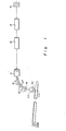
- Figure 1 is a schematic view in side elevation of the delivery end of a rod mill employing driven pinch rolls in accordance with the present invention;
- Figure 2 is an enlarged side elevational view of the pinch roll unit;
- Figure 3 is a top plan view of the pinch roll unit;
- Figure 4 is a vertical sectional view taken through the pinch roll unit on line 4-4 of Figure 3;
- Figures 5 and 6 are horizontal sectional views of the pinch roll unit taken respectively along lines 5-5 and 6-6 of Figure 2; and,
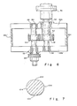
- Figure 7 is an enlarged cross section of a typical - rod front end after it has been passed through the pinch roll unit, with the deformation imparted as a result of the initial pinch roll setting being exaggerated for purposes of illustration.
- Referring initially to Figure 1, the last mill stand of a rolling mill finishing train is indicated at 10. Hot rolled rod emerging from
mill stand 10 is directed substantially horizontally through a series ofconventional water boxes 12 and then on through apinch roll unit 14 in accordance with the present invention. The pinch roll unit is positioned immediately upstream from a downwardly curved path "P" defined by a curved closed pipe, or preferably by a curved open-sided guide pipe 16 and a plurality of freely rotatable guide rollers indicated typically at 18. After negotiating the downwardly curved path P, the rod enters aconventional laying head 20 which forms the rod into a series ofrings 22. The rings are received on anunderlying conveyor 24 where they are arranged in an offset overlapping pattern. While on the conveyor, the rod rings are subjected to additional controlled cooling to achieve desired metallurgical properties. Once this has been accomplished, the rings are removed from the delivery end of the conveyor and accumulated into coils. With the exception of thepinch roll unit 14, the foregoing represents conventional practice now well known to those skilled in the art. - Referring now to Figures 2-6, the
pinch roll unit 14 includes afixed housing structure 26 having abottom plate 26a,side walls end walls - A
lower gear shaft 30 is journalled for rotation on a fixed axis betweenbearings 32 which are carried by thehousing side walls inner housing 34 is contained within thestationary housing structure 26. As shown in Figure 5, the inner housing includes side plates 34a, 34a' joined byend plates sleeves sleeves 34c are pivotally journalled inbearings 36 carried by thehousing side walls sleeves 34d are movable freely inopenings 37 in the housing side walls. An upper gear shaft 38-is journalled for rotation betweenbearings 40 contained in thesleeves 34c. The rotational axis ofupper gear shaft 38 and the pivotal axis ofhousing 34 as defined bysleeves 34c are coincident and parallel to the rotational axis of thelower gear shaft 30. Thegear shafts gears lower gear shaft 30 protrudes throughhousing side wall 26b where it is connected by acoupling 46 to a conventional drive (not shown). - . A
lower roll shaft 50 is journalled for rotation on a fixed axis betweenbearings 52 carried by thehousing side walls Lower roll shaft 50 carries agear 54 in meshed relationship withgear 42 onlower gear shaft 30. - An
upper roll shaft 56 is rotatably journalled betweenbearings 58 carried in thesleeves 34d ofinner housing 34. Theupper roll shaft 56 carries agear 60 which is in meshed relationship withgear 44 onupper gear shaft 38. Theroll shafts pinch rolls - The
inner housing 34 hasears end plates forward ear 66 is arranged to contact an adjustable stop in the form of aheavy duty bolt 70. Thebolt 70 is threaded through thehousing top plate 26b and is held at any selected setting by means of alock nut 74. - The
rearward ear 68 is arranged to contact aspherical cap 76 which is urged upwardly to ahelical spring 82.Ear 68 is connected as at 86 tointermediate links 88 which are in turn connected as at 90 to a cross bar on the piston rod 96a of apneumatic cylinder 96.Inner housing 34 is additionally provided with anupstanding nose 98 arranged to be contacted by the ram 100a of a heavy dutyhydraulic cylinder 100. - With this arrangement, the
lower pinch roll 62 remains fixed, and roll parting is changed by pivotally adjusting theinner housing 34 about the axis ofupper gear shaft 38. Throughout such adjustments, the 4-gear cluster consisting ofgears - The method of operating the
pinch roll unit 14 in accordance with the present invention is as follows: before the leading end of a rod is received at the pinch roll unit, thebolt 70 is adjusted in relation to the forwardly extendingear 66 to achieve an initial parting between thepinch rolls hydraulic ram 100 is actuated to exert an initial closing force which pivots theinner housing 34 in a counterclockwise direction, thereby firmly holding theear 66 against the lower end of thebolt 70. This initial closing force, which easily overcomes the opposing force ofspring 82, is greater than the momentary surge in separating force to which the pinch rolls will be subjected when the rod front end enters the pinch roll gap. The initial pinch roll parting is sized to impart some deformation to the rod passing therebetween. As shown in Figure 7, this deformation will consist of a slight flattening at the top and bottom of the rod as at 102 with accompanying slight bulges at the sides as at 104. This type of deformation is similar to that occurring in a mill stand taking a light reduction. - A
conventional mill guide 106 is provided to direct the leading end of an oncoming rod between thepinch rolls bolt 70 and the high initial level of closing force exerted by thehydraulic ram 100 insures that the pinch roll nip will remain in a steady-state condition during rod entry, thereby providing an uninterrupted driving force which propels the rod around the downwardly curved path P and through the layinghead 20. After the rod has passed through the laying head (typically after the first one or two rings have been laid on the conveyor 24), thehydraulic ram 100 is deactivated. This can be accomplished by any conventional control arrangement, such as for example by sensing the increased load on the pinch roll drive at the time of rod entry and by employing a pulse counter to emit a signal to a solenoid controlling the hydraulic ram after a selected time delay. As soon as the hydraulic ram is deactivated, the high initial closing force is released. When this occurs, the separating force exerted on the pinch rolls by the rod passing therebetween pivots theinner housing 34 in a clockwise direction against a lower secondary closing force supplied by thepneumatic cylinder 96. The secondary closing force is adequate to maintain a secondary parting between the pinch rolls which eliminates the aforesaid rod deformation while continuing to propel the rod along curved path P and through the laying head. This condition is maintained until the tail end of the rod has passed through the pinch roll unit. Alternatively, thepneumatic cylinder 96 can be set to allow the rod to run freely between the pinch rolls after deactivation of thehydraulic ram 100. Once a rod has passed through the pinch roll unit, the hydraulic ram is again activated to reset the pinch rolls to their initial parting in preparation for receipt of the next rod front end.
Claims (10)
Priority Applications (1)
| Application Number | Priority Date | Filing Date | Title |
|---|---|---|---|
| AT82300713T ATE13261T1 (en) | 1981-02-13 | 1982-02-12 | ROLLING MILL. |
Applications Claiming Priority (2)
| Application Number | Priority Date | Filing Date | Title |
|---|---|---|---|
| US234115 | 1981-02-13 | ||
| US06/234,115 US4413494A (en) | 1981-02-13 | 1981-02-13 | Pinch roll system for vertical laying heads |
Publications (3)
| Publication Number | Publication Date |
|---|---|
| EP0058538A2 EP0058538A2 (en) | 1982-08-25 |
| EP0058538A3 EP0058538A3 (en) | 1983-03-30 |
| EP0058538B1 true EP0058538B1 (en) | 1985-05-15 |
Family
ID=22879987
Family Applications (1)
| Application Number | Title | Priority Date | Filing Date |
|---|---|---|---|
| EP82300713A Expired EP0058538B1 (en) | 1981-02-13 | 1982-02-12 | Rolling mills |
Country Status (8)
| Country | Link |
|---|---|
| US (1) | US4413494A (en) |
| EP (1) | EP0058538B1 (en) |
| JP (1) | JPS57154324A (en) |
| AT (1) | ATE13261T1 (en) |
| BR (1) | BR8200634A (en) |
| CA (1) | CA1170868A (en) |
| DE (1) | DE3263477D1 (en) |
| IN (1) | IN157706B (en) |
Families Citing this family (10)
| Publication number | Priority date | Publication date | Assignee | Title |
|---|---|---|---|---|
| JPS5948538A (en) * | 1982-09-04 | 1984-03-19 | 小堀住研株式会社 | Wooden prefabricated house structure |
| US5170653A (en) * | 1990-09-07 | 1992-12-15 | Bethlehem Steel Corporation | Method for coiling twist free steel bars |
| US5423200A (en) * | 1993-09-14 | 1995-06-13 | Morgan Construction Company | Rolling mill material handling system |
| DE19800201A1 (en) * | 1998-01-07 | 1999-07-15 | Schloemann Siemag Ag | Roll stand for rolling wire |
| US6920772B1 (en) * | 2003-02-12 | 2005-07-26 | Morgan Construction Company | Pinch roll unit |
| US7861567B2 (en) * | 2005-11-22 | 2011-01-04 | Og Technologies, Inc. | Method and apparatus to control the lateral motion of a long metal bar being formed by a mechanical process such as rolling or drawing |
| US7275404B1 (en) | 2005-11-22 | 2007-10-02 | Og Technologies, Inc. | Method and an apparatus to control the lateral motion of a long metal bar being formed by a mechanical process such as rolling or drawing |
| US7207202B1 (en) * | 2006-05-30 | 2007-04-24 | Morgan Construction Company | Method of subdividing and decelerating hot rolled long products |
| US8707748B2 (en) * | 2010-07-01 | 2014-04-29 | Siemens Industry, Inc. | Turn down apparatus |
| CN112958668B (en) * | 2021-02-03 | 2022-12-20 | 苏州芙路得智能科技有限公司 | Detection equipment for resilience position of bent pipe |
Family Cites Families (13)
| Publication number | Priority date | Publication date | Assignee | Title |
|---|---|---|---|---|
| US2190429A (en) * | 1937-05-11 | 1940-02-13 | Motor Products Corp | Rolling machine |
| US2231400A (en) * | 1937-08-25 | 1941-02-11 | American Rolling Mill Co | Hot coiler feeding means and method |
| US2179011A (en) * | 1938-02-28 | 1939-11-07 | American Rolling Mill Co | Hot strip coiling machine |
| US2245407A (en) * | 1938-09-02 | 1941-06-10 | Gen Motors Corp | Apparatus for roll forming strip material |
| US2653496A (en) * | 1947-11-25 | 1953-09-29 | American Brass Co | Rolling mill and coiling apparatus |
| US3036622A (en) * | 1958-02-28 | 1962-05-29 | Gifford L Hitz | Process of bending metal by wave formation |
| DE2100088C3 (en) * | 1971-01-02 | 1980-08-21 | Bindernagel, Ali, 5632 Wermelskirchen | Coiler furnace for a continuous fine iron rolling mill |
| US3680758A (en) * | 1971-03-03 | 1972-08-01 | Morgan Construction Co | Slant disc entry guide |
| US3842473A (en) * | 1971-12-22 | 1974-10-22 | Glacier Metal Co Ltd | Bearings |
| FR2211298B1 (en) * | 1972-12-21 | 1980-08-08 | Properzi Giulio | |
| JPS5947617B2 (en) * | 1977-12-30 | 1984-11-20 | 日本発条株式会社 | Manufacturing method of taper leaf spring |
| JPS5920411B2 (en) * | 1978-05-30 | 1984-05-12 | 日本発条株式会社 | Width adjustment device for taper rolling of leaf springs |
| US4344309A (en) * | 1978-10-20 | 1982-08-17 | Kawasaki Steel Corporation | Process for preventing growth of fishtails during slabbing |
-
1981
- 1981-02-13 US US06/234,115 patent/US4413494A/en not_active Expired - Fee Related
-
1982
- 1982-01-22 CA CA000394711A patent/CA1170868A/en not_active Expired
- 1982-01-25 IN IN56/DEL/82A patent/IN157706B/en unknown
- 1982-02-05 BR BR8200634A patent/BR8200634A/en unknown
- 1982-02-12 EP EP82300713A patent/EP0058538B1/en not_active Expired
- 1982-02-12 DE DE8282300713T patent/DE3263477D1/en not_active Expired
- 1982-02-12 AT AT82300713T patent/ATE13261T1/en not_active IP Right Cessation
- 1982-02-13 JP JP57020704A patent/JPS57154324A/en active Pending
Also Published As
| Publication number | Publication date |
|---|---|
| IN157706B (en) | 1986-05-24 |
| US4413494A (en) | 1983-11-08 |
| EP0058538A3 (en) | 1983-03-30 |
| ATE13261T1 (en) | 1985-06-15 |
| JPS57154324A (en) | 1982-09-24 |
| BR8200634A (en) | 1982-12-14 |
| CA1170868A (en) | 1984-07-17 |
| DE3263477D1 (en) | 1985-06-20 |
| EP0058538A2 (en) | 1982-08-25 |
Similar Documents
| Publication | Publication Date | Title |
|---|---|---|
| US4413494A (en) | Pinch roll system for vertical laying heads | |
| LT3832B (en) | Method for obtaining of steel tape by hot rolling, tape device for pouring out | |
| JPS585132B2 (en) | Equipment for cutting, distributing and shredding high-speed rolling rolled stock | |
| CA1160550A (en) | Straightening apparatus for steel pipes and the like | |
| DE69229896T2 (en) | Method and device for making wire | |
| US5966978A (en) | Reeling unit for strip | |
| EP1446242B1 (en) | Method and device for the continuous production of a rolled metal strip from a molten metal | |
| DE2100088C3 (en) | Coiler furnace for a continuous fine iron rolling mill | |
| CA2448784C (en) | Bar delivery system and method | |
| CA2313345A1 (en) | Tension control system and method for reducing front end and tail end overfill of a continuously hot rolled product | |
| CA2509325C (en) | Method and installation for hot rolling strip with a steckel rolling stand | |
| US4289011A (en) | Continuous pipe rolling process | |
| US1985501A (en) | High speed hot coiler | |
| EP0560093B1 (en) | Small section-/wire rod mill | |
| EP0242104A1 (en) | Strip guiding for downcoilers | |
| DE10357272A1 (en) | Process for hot rolling steel strips comprises cropping the strip using reverse rolling in a Steckel mill using crop shears arranged between a driver and the mill | |
| EP0195583B1 (en) | Control of a cross helical rolling mill | |
| US3422654A (en) | Rolling mill | |
| JPH062282B2 (en) | Crank mill for continuous hot rolling equipment | |
| US5220819A (en) | Entry guide for strip mill | |
| US4884429A (en) | Decelerator apparatus for hot rolled product | |
| US5992201A (en) | Rolling and shearing process and apparatus background | |
| JPH0339763B2 (en) | ||
| US4435886A (en) | Pipe-welding mill for production of coiled pipes | |
| EP0129497B1 (en) | Cross-rolling mill with conical rolls |
Legal Events
| Date | Code | Title | Description |
|---|---|---|---|
| PUAI | Public reference made under article 153(3) epc to a published international application that has entered the european phase |
Free format text: ORIGINAL CODE: 0009012 |
|
| AK | Designated contracting states |
Designated state(s): AT BE CH DE FR GB IT LI LU NL SE |
|
| PUAL | Search report despatched |
Free format text: ORIGINAL CODE: 0009013 |
|
| RHK1 | Main classification (correction) |
Ipc: B21B 41/00 |
|
| AK | Designated contracting states |
Designated state(s): AT BE CH DE FR GB IT LI LU NL SE |
|
| 17P | Request for examination filed |
Effective date: 19830702 |
|
| ITF | It: translation for a ep patent filed | ||
| GRAA | (expected) grant |
Free format text: ORIGINAL CODE: 0009210 |
|
| AK | Designated contracting states |
Designated state(s): AT BE CH DE FR GB IT LI LU NL SE |
|
| PG25 | Lapsed in a contracting state [announced via postgrant information from national office to epo] |
Ref country code: LI Effective date: 19850515 Ref country code: CH Effective date: 19850515 |
|
| REF | Corresponds to: |
Ref document number: 13261 Country of ref document: AT Date of ref document: 19850615 Kind code of ref document: T |
|
| REF | Corresponds to: |
Ref document number: 3263477 Country of ref document: DE Date of ref document: 19850620 |
|
| ET | Fr: translation filed | ||
| REG | Reference to a national code |
Ref country code: CH Ref legal event code: PL |
|
| PG25 | Lapsed in a contracting state [announced via postgrant information from national office to epo] |
Ref country code: LU Free format text: LAPSE BECAUSE OF NON-PAYMENT OF DUE FEES Effective date: 19860228 |
|
| PLBE | No opposition filed within time limit |
Free format text: ORIGINAL CODE: 0009261 |
|
| STAA | Information on the status of an ep patent application or granted ep patent |
Free format text: STATUS: NO OPPOSITION FILED WITHIN TIME LIMIT |
|
| 26N | No opposition filed | ||
| PGFP | Annual fee paid to national office [announced via postgrant information from national office to epo] |
Ref country code: AT Payment date: 19870202 Year of fee payment: 6 |
|
| PGFP | Annual fee paid to national office [announced via postgrant information from national office to epo] |
Ref country code: NL Payment date: 19870228 Year of fee payment: 6 |
|
| PGFP | Annual fee paid to national office [announced via postgrant information from national office to epo] |
Ref country code: LU Payment date: 19890208 Year of fee payment: 8 |
|
| PG25 | Lapsed in a contracting state [announced via postgrant information from national office to epo] |
Ref country code: GB Effective date: 19890212 Ref country code: AT Effective date: 19890212 |
|
| PG25 | Lapsed in a contracting state [announced via postgrant information from national office to epo] |
Ref country code: SE Effective date: 19890213 |
|
| PGFP | Annual fee paid to national office [announced via postgrant information from national office to epo] |
Ref country code: BE Payment date: 19890313 Year of fee payment: 8 |
|
| PG25 | Lapsed in a contracting state [announced via postgrant information from national office to epo] |
Ref country code: NL Effective date: 19890901 |
|
| NLV4 | Nl: lapsed or anulled due to non-payment of the annual fee | ||
| GBPC | Gb: european patent ceased through non-payment of renewal fee | ||
| PG25 | Lapsed in a contracting state [announced via postgrant information from national office to epo] |
Ref country code: FR Free format text: LAPSE BECAUSE OF NON-PAYMENT OF DUE FEES Effective date: 19891027 |
|
| PG25 | Lapsed in a contracting state [announced via postgrant information from national office to epo] |
Ref country code: DE Effective date: 19891101 |
|
| REG | Reference to a national code |
Ref country code: FR Ref legal event code: ST |
|
| PG25 | Lapsed in a contracting state [announced via postgrant information from national office to epo] |
Ref country code: BE Effective date: 19900228 |
|
| BERE | Be: lapsed |
Owner name: MORGAN CONSTRUCTION CY Effective date: 19900228 |
|
| EUG | Se: european patent has lapsed |
Ref document number: 82300713.3 Effective date: 19900118 |