EP0058040A1 - Installation for the transportation of bulk material between a shore and an offshore naval vessel - Google Patents
Installation for the transportation of bulk material between a shore and an offshore naval vessel Download PDFInfo
- Publication number
- EP0058040A1 EP0058040A1 EP82300528A EP82300528A EP0058040A1 EP 0058040 A1 EP0058040 A1 EP 0058040A1 EP 82300528 A EP82300528 A EP 82300528A EP 82300528 A EP82300528 A EP 82300528A EP 0058040 A1 EP0058040 A1 EP 0058040A1
- Authority
- EP
- European Patent Office
- Prior art keywords
- conveyor belt
- station
- loading
- unloading
- offshore
- Prior art date
- Legal status (The legal status is an assumption and is not a legal conclusion. Google has not performed a legal analysis and makes no representation as to the accuracy of the status listed.)
- Withdrawn
Links
- 239000013590 bulk material Substances 0.000 title claims abstract description 21
- 238000009434 installation Methods 0.000 title claims abstract description 19
- 230000009466 transformation Effects 0.000 claims abstract description 29
- 230000000712 assembly Effects 0.000 claims description 7
- 238000000429 assembly Methods 0.000 claims description 7
- 238000010276 construction Methods 0.000 abstract description 2
- 239000003245 coal Substances 0.000 description 8
- 230000005540 biological transmission Effects 0.000 description 5
- XLYOFNOQVPJJNP-UHFFFAOYSA-N water Substances O XLYOFNOQVPJJNP-UHFFFAOYSA-N 0.000 description 3
- XEEYBQQBJWHFJM-UHFFFAOYSA-N Iron Chemical compound [Fe] XEEYBQQBJWHFJM-UHFFFAOYSA-N 0.000 description 2
- 238000004873 anchoring Methods 0.000 description 2
- 230000000284 resting effect Effects 0.000 description 2
- 229910001570 bauxite Inorganic materials 0.000 description 1
- 238000001816 cooling Methods 0.000 description 1
- 238000005553 drilling Methods 0.000 description 1
- 231100001261 hazardous Toxicity 0.000 description 1
- 230000008676 import Effects 0.000 description 1
- 229910052742 iron Inorganic materials 0.000 description 1
- 239000000463 material Substances 0.000 description 1
- 239000002480 mineral oil Substances 0.000 description 1
- 235000010446 mineral oil Nutrition 0.000 description 1
- 238000003032 molecular docking Methods 0.000 description 1
- 239000003921 oil Substances 0.000 description 1
- 238000005192 partition Methods 0.000 description 1
- 230000035515 penetration Effects 0.000 description 1
- 239000002367 phosphate rock Substances 0.000 description 1
- 239000011435 rock Substances 0.000 description 1
- 238000007665 sagging Methods 0.000 description 1
- 239000013535 sea water Substances 0.000 description 1
- 230000001360 synchronised effect Effects 0.000 description 1
- 230000001131 transforming effect Effects 0.000 description 1
Images


Classifications
-
- B—PERFORMING OPERATIONS; TRANSPORTING
- B65—CONVEYING; PACKING; STORING; HANDLING THIN OR FILAMENTARY MATERIAL
- B65G—TRANSPORT OR STORAGE DEVICES, e.g. CONVEYORS FOR LOADING OR TIPPING, SHOP CONVEYOR SYSTEMS OR PNEUMATIC TUBE CONVEYORS
- B65G21/00—Supporting or protective framework or housings for endless load-carriers or traction elements of belt or chain conveyors
- B65G21/005—Supporting or protective framework or housings for endless load-carriers or traction elements of belt or chain conveyors for conveyors floating on liquids
-
- B—PERFORMING OPERATIONS; TRANSPORTING
- B65—CONVEYING; PACKING; STORING; HANDLING THIN OR FILAMENTARY MATERIAL
- B65G—TRANSPORT OR STORAGE DEVICES, e.g. CONVEYORS FOR LOADING OR TIPPING, SHOP CONVEYOR SYSTEMS OR PNEUMATIC TUBE CONVEYORS
- B65G15/00—Conveyors having endless load-conveying surfaces, i.e. belts and like continuous members, to which tractive effort is transmitted by means other than endless driving elements of similar configuration
- B65G15/08—Conveyors having endless load-conveying surfaces, i.e. belts and like continuous members, to which tractive effort is transmitted by means other than endless driving elements of similar configuration the load-carrying surface being formed by a concave or tubular belt, e.g. a belt forming a trough
-
- B—PERFORMING OPERATIONS; TRANSPORTING
- B65—CONVEYING; PACKING; STORING; HANDLING THIN OR FILAMENTARY MATERIAL
- B65G—TRANSPORT OR STORAGE DEVICES, e.g. CONVEYORS FOR LOADING OR TIPPING, SHOP CONVEYOR SYSTEMS OR PNEUMATIC TUBE CONVEYORS
- B65G15/00—Conveyors having endless load-conveying surfaces, i.e. belts and like continuous members, to which tractive effort is transmitted by means other than endless driving elements of similar configuration
- B65G15/60—Arrangements for supporting or guiding belts, e.g. by fluid jets
-
- B—PERFORMING OPERATIONS; TRANSPORTING
- B65—CONVEYING; PACKING; STORING; HANDLING THIN OR FILAMENTARY MATERIAL
- B65G—TRANSPORT OR STORAGE DEVICES, e.g. CONVEYORS FOR LOADING OR TIPPING, SHOP CONVEYOR SYSTEMS OR PNEUMATIC TUBE CONVEYORS
- B65G2201/00—Indexing codes relating to handling devices, e.g. conveyors, characterised by the type of product or load being conveyed or handled
- B65G2201/04—Bulk
Definitions
- the present invention concerns an installation for the transportation of bulk material between a location on a shore and a naval vessel anchoring offshore.
- an installation for the transportation of bulk material between a shore and an offshore naval vessel comprising:
- an installation according to the invention will comprise a number of conveyor belts running in parallel and designed for simultaneous or selective operation, as may be required.
- each conveyor belt is designed either for loading or unloading a naval vessel.
- the shore station is the loading station and comprises a transformation assembly of the first kind
- the offshore station is the unloading station and comprises a transformation assembly of the second kind.
- the offshore station is the loading station and comprises a transformation assembly of the first kind
- the shore station is the unloading station and comprises a transformation assembly of the second kind.
- either ofsaid shore and offshore stations is fitted in association with each conveyor belt with both transformation assemblies of the first and second kind for alternative use, and in this way each conveyor belt may be used for either loading or unloading a naval vessel, as may be required.
- the offshore station may be fixed or movable.
- a fixed station may be installed on a platform resting on a plurality of poles or legs, e.g. of the kind that is used for offshore oil drilling.
- a movable station may be located on a floating vessel, e.g. a barge and has the advantage that it can serve sequentially several ships without that the latter have to move.
- the loaded part of the conveyor belt that is in a tubular state floats on the water across the stretch of sea between the shore and offshore stations.
- the unloaded part of the conveyor belt that is in a flat state travels submerged underneath the loaded part and in opposite direction.
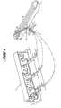
- the installation according to the invention shown in Fig. 1 comprises a shore station 1, an offshore station 2 located on a barge 3 and three identical endless conveyor belts 4 forming a loop at each station and travelling between stations 1 and 2 across the open sea such that the conveyor belt is in a loaded, tubular state 4" on the leg between the offshore station 2 to the shore station 1 and in an unloaded flat state 4' on the leg from shore station 1 to offshore station 2.
- the shore and offshore stations are shown in two different perspectives and the conveyor belts are partly broken away. In actual practice, the conveyor belts extend straightly between the stations.
- the shore station 1 comprises associated with each conveyor belt 4 a driving motor 5 and transmission means 6.
- the motors 5 may be operated simultaneously or selectively as may be required.
- the offshore station 2 comprises a hopper 7 through which bulk material is dumped onto the conveyor belts 4.
- a ship 8 is anchored close to the barge 3 and the bulk material arriving from the interior of the ship is dumped into hopper 7 through a chute 9.
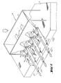
- hopper 7 is designed for the distribution of the bulk material arriving through chute 9 between the three conveyor belts 4.
- internal partitions 10 subdividing the hopper into three compartments each terminating with an outlet 11 associated with one of the conveyor belts 4.
- each conveyor belt 4 At the offshore station 2 there is associated with each conveyor belt 4 a driving motor 12, transmission means 13, and a clutch 14.
- each conveyor belt is driven at both loops by motors 5 and 12 through respectively transmission means 6 and 13.
- each pair of motors 5 and 12 associated with one and the same conveyor belts 4 are synchronized.
- each conveyor belt 4 at the offshore station 2 There is further associated with each conveyor belt 4 at the offshore station 2 a transformation assembly of the first kind for transforming the conveyor belt from the flattened state 4' into the tubular state 4''.
- Each transformation assembly of the first kind is symbolized in Fig. 2 by a pair of idler rollers 15 and such an assembly will be described in more detail further below.
- each conveyor belt arrives at the offshore station 2 from the shore station 1 through the stretch of open sea between them in the flattened state 4' and returns from the offshore station 2 to the shore station 1, again through the stretch of open sea between them by floating in the tubular state 4"..
- Each of the transformation assemblies of the first and second kind consists of a plurality of idler rollers and wheels serving as guides. They are suitably shaped and positioned so as to fold the conveyor belts into a tubular state and cause the two edges to interlock in case of transformation assembly of the first kind, and to tear it open and cause it to flatten out in case of a transformation assembly of the second kind.
- the rollers and wheels of the transformation assemblies of either kind are mounted on a framework installed overhead the associated conveyor belt near the loop portion thereof. For simplicity of illustration, said frameworks are not illustrated in the drawings which merely show the rollers and wheels as such.
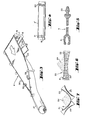
- the offshore loop portion of a conveyor belt 4 serving for loading the conveyor (unloading a ship) is shown in Fig. 3.
- the conveyor belt arriving in the flattened state 4' from the shore station forms a loop over and between rollers 16, 17 and 18, the latter being driven by the associated motor 12 through transmission means 13 and clutch 14.
- the upper, still flattened part of the loop receives bulk material (not shown) that is dumped from an associated outlet 11 of hopper 7.
- the so-loaded conveyor belt 4 is then folded over into the tubular state 4".
- the end portions of roller 17 are profiled so as to receive the profiled edges of the conveyor belt 4. These edges are more closely illustrated in Fig. 5 and it can be seen that one of them has a male profile 20 and the other a female profile 21, said profiles 20, 21 being adapted for tight interlock.
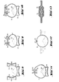
- the transformation assembly of the first kind associated with the loop portion of conveyor belt 4 shown in Fig. 3 comprises a plurality of idler rollers and wheels of different shapes and sizes as shown in Figs. 6-11.
- the first part of the transformation assembly is shown in Fig. 6 and it consists of a set 22 of idler wheels 23 whose diameters decrease symmetrically from the flank to the centre such that the conveyor belt 4 resting thereon is caved so as to better hold the dumped-on bulk material 24.
- Rollers 25 have each a caved-in shape so that between them they induce further sagging of the conveyor belt 4 as shown in Fig. 7.
- rollers 26 are of similar shape as rollers 25 in F ig. 5 and as is shown one of them extends transversely and serves as support, while the two flanking rollers 26 are mounted vertically, so that the three rollers 26 form between them an essentially U-shaped assembly. Due to this the conveyor belt 4 passing through roller 26 also assumes a U-shaped profile.
- Fig. 9 There then follows the assembly shown in Fig. 9. It comprises below a transversal roller 27 of similar shape and design as roller 26 in Fig. 8 and again serving as support.
- a transversal roller 27 of similar shape and design as roller 26 in Fig. 8 and again serving as support.
- This assembly again comprises a lower, transversal idler roller 30 of similar shape and design as rollers 26 and 27 of, respectively, Figs. 8 and 9 and again serving as support.
- two differently shaped overhead idler wheels depending from a flat bracket 31.
- the first of these, wheel 32 has a truncated conical shape and is adapted to guide the male profiled edge 20 of conveyor belt 4 into a horizontal position.
- the other wheel 33 is:of double truncated conical shape and is adapted to penetrate into a portion of the female edge 21 of conveyor belt 4 so as to widen it and place it exactly opposite the male portion 20.
- Fig. 13 shows to a larger scale the interlock between edges 20 and 21 of the conveyor belt 4.
- Fig. 14 shows the delivery loop of a conveyor belt 4 at the shore station 1.
- the conveyor belt in its tubular state 4" gradually opens and is transformed into the flattened state 4' in which it returns submerged to the offshore station 2.
- the loop end of the conveyor belt passes over and between rollers 40, 41, 42, the former of which is directly driven by motor 5 via transmission means 6 and a clutch 43.
- the transformation assembly of the second kind is here symbolized by pairs of rollers 44 and 45 and will be described in more detail further below.
- a hopper 46 which directs the dumped-off bulk material onto a transversal conveyor belt 47 from where the material is dumped on a further conveyor belt 48 which delivers the bulk material for further disposal.
- the delivery loop of the conveyor belt is shown more closely in Fig. 15 and it is seen there how it transforms from the tubular state 4" into the fully flattened state 4' passing on its way over and between rollers 40, 41, 42..
- the arriving conveyor belt 4 in the tubular state 4" is stabilized by a supporting idler roller 50 of similar shape and size as rollers 26, 27, 30 and 34 of, respectively, Figs. 8, 9, 10 and 11.
- a supporting idler roller 50 of similar shape and size as rollers 26, 27, 30 and 34 of, respectively, Figs. 8, 9, 10 and 11.
- an unlocking assembly shown in Fig. 17. It comprises another similar supporting roller 51 and, suspended from a bracket 52 an overhead idler wheel 53 of double conical shape adapted for penetration into the female edge 21 of conveyor belt 4, and a grooved wheel 54 adapted to receive the male edge 20 of the conveyor belt.
- Fig. 19 It comprises below conveyor belt 4 a plurality of idler wheels 58 whose diameter diminishes symmetrically from the flanks to the centre, similar as the set of wheels 23 in Fig. 6.
- the assembly further comprises a pair of upper rollers 59 which press the conveyor belt 4 from above and thereby ensure a further flattening thereof as shown in Fig. 19.
- the installation according to the invention will work in the same way for loading ships and in this case the shore station will serve for dumping bulk material onto the conveyor belt and will comprise trasnformation assemblies of the first kind while the offshore station will serve for unloading and will comprise transformation assemblies of the second kind. It is furthermore easily understood that at either station there may be provided in association with each conveyor belt 4 two sets of transformation assemblies, one of the first kind and the other of the second kind, for alternative use. In this way the assembly can be used either for loading or unloading, as may be required.
Landscapes
- Engineering & Computer Science (AREA)
- Mechanical Engineering (AREA)
- Structure Of Belt Conveyors (AREA)
- Ship Loading And Unloading (AREA)
Abstract
installations for loading and unloading naval vessels anchored offshore. Each installation comprises in combination:
- i) a shore station (1) and an offshore station (2), one serving for loading (loading station) and the other for unloading (unloading station);
- ii) at least one endless conveyor belt (4) travelling across the sea between said stations forming a loop at either station and adapted to be transformed when loaded into a tubular state and to float in such state;
- iii) locking means (20,21) at the edges of edges of each of said conveyor belt adapted to interlock when forced against each other;
- iv) means (7) associated with each conveyor belt at the loading station for loading bulk material thereon;
- v) further means (25-35) associated with each conveyor belt at the loading station for causing the loaded conveyor belt to fold over and said locking means to interlock thereby to transform the conveyor belt into a tubular state (4") (transformation assembly of the first kind);
- vi) means (44, 45) associated with each conveyor belt at the unloading station for unlocking said locking means and opening and flattening the conveyor belt thereby to transform the conveyor belt into a flattened state (4') (transformation assembly of the second kind); and
- vii) further means (46, 47) associated with each conveyor belt at the unloading station for receiving dumped-off bulk material.
By means of such installations loading and unloading can be effected near the site from where the loaded bulk is obtained, e.g. a mine, or near the site where the unloaded bulk is required, e.g. a power station. In this way the construction of expensive harbours can be avoided and transportation costs are reduced.
Description
- The present invention concerns an installation for the transportation of bulk material between a location on a shore and a naval vessel anchoring offshore.
- The need for the loading and unloading of bulk material onto and from naval vessels anchoring offshore has recently become ever more pressing. For example, in view of the energy crisis due to the ever increasing price of mineral oil, new power stations are being erected operating on coal. Such stations are usually erected on the seaside in order to utilize sea water for cooling, and for ecological considerations out as far as possible from densely populated areas. Many of the countries that build coal-operated power stations do not have any coal of their own and have to import it by sea from abroad and obviously it is preferred that the coal should be brought directly to the site of the power station without the need for any intermediary land transportation. For considerations of costs and ecology it is required that the unloading of coal from the ships should be effected offshore. Hitherto, the designers have met this requirement by erecting long piers leading from the site of the power station to a desired distance offshore where it is safe for coal freighters to anchor, and obviously thelarger the freighters that are to be used the longer the pier has to be. Experience has shown-that the building of a long pier extending deep into open sea to a location where it is safe for the large-size freighters to anchor is an expensive operation, which in the absence of a natural harbour may also be hazardous. Such, for example, is the case at the site of the new power station at Hadera, Israel, which is now under construction. Furthermore, the docking of freighters near piers in mid-sea and the unloading of freight becomes impossible at rought sea conditions which in many locations, such as at-the Hadera site, is liable to occur during 30% of the time or even more. However, so far designers have been looking in vain for a cheaper, safer and more reliable means for the offshore unloading of coal.
- Similar problems arise for loading coal. Here too, for considerations of ecology it is desired to load the coal outside of large multipurpose harbours from a shore station outside populated areas onto freighters that anchor offshore.
- Similar problems arise with other bulk material such as ores of various kinds, e.g. phosphate rock, iron ores, bauxite, various calcareous rocks, and the like which for reasons of convenience and ecology it is desired to load onto ships or unload from ships that are anchored offshore.
- It is thus the object of the present invention to provide a new installation for solving all these problems.
- In accordance with the invention there is provided an installation for the transportation of bulk material between a shore and an offshore naval vessel, comprising:
- i) a shore station and an offshore station, one serving for loading (loading station) and the other for unloading (unloading station);
- ii) at least one endless conveyor belt, travelling across the sea between said stations forming a loop at either station and adapted to be transformed when loaded into a tubular state and to float in such state;
- iii) locking means-at the edges of each of said conveyor belt adapted to interlock when forced against each other;
- iv) means associated with each conveyor belt at the loading station for loading bulk material thereon;
- v) further means associated with each conveyor belt at the loading station for causing the loaded conveyor belt to fold over and said locking means to interlock thereby to transform the conveyor belt into a tubular state (transformation assembly of the first kind);
- vi) means associated with each conveyor belt at the unloading station for unlocking said locking means andopening and flattening the conveyor belt thereby to transform the conveyor belt into a flattened state (transformation assembly of the second kind); and
- vii) further means associated with each conveyor belt at the unloading station for receiving dumped-off bulk material.
- As a rule, an installation according to the invention will comprise a number of conveyor belts running in parallel and designed for simultaneous or selective operation, as may be required.
- In accordance with one embodiment of the invention, each conveyor belt is designed either for loading or unloading a naval vessel. When the design is for loading the shore station is the loading station and comprises a transformation assembly of the first kind, and the offshore station is the unloading station and comprises a transformation assembly of the second kind. When the design is for unloading a naval vessel the offshore station is the loading station and comprises a transformation assembly of the first kind and the shore station is the unloading station and comprises a transformation assembly of the second kind.
- In accordance with another embodiment of the invention either ofsaid shore and offshore stations is fitted in association with each conveyor belt with both transformation assemblies of the first and second kind for alternative use, and in this way each conveyor belt may be used for either loading or unloading a naval vessel, as may be required.
- In accordance with the invention the offshore station may be fixed or movable. A fixed station may be installed on a platform resting on a plurality of poles or legs, e.g. of the kind that is used for offshore oil drilling. A movable station may be located on a floating vessel, e.g. a barge and has the advantage that it can serve sequentially several ships without that the latter have to move.
- In operation, the loaded part of the conveyor belt that is in a tubular state floats on the water across the stretch of sea between the shore and offshore stations. The unloaded part of the conveyor belt that is in a flat state travels submerged underneath the loaded part and in opposite direction.
- The invention is illustrated, by way of example only, in the accompanying drawings in which:
- Fig. 1 is a perspective view of an installation according to the invention;
- Fig. 2 is a perspective view of the offshore station in the installation of Fig. 1, drawn to a larger scale;
- Fig. 3 shows the loop portion of a conveyor belt at the offshore station of Fig. 2, drawn to a larger scale;
- Fig. 4 shows a detail of the loop;
- Fig. 5 shows the interlocking edges of the conveyor belt of Fig. 3;
- Figs. 6-11 are details of the transformation means of the first'kind associated with the offshore end of the conveyor belt shown in Fig. 3, all drawn to a larger scale;
- Fig. 12 shows;the loaded conveyor belt in its floating tubular state;
- Fig. 13 shows to a larger scale the interlock between the two edges of the conveyor belt;
- Fig. 14 is a fragmentary perspective view of the shore station of the installation of Fig. 1, drawn to a larger scale;
- Fig. 15 shows the loop portion of the conveyor belt of Fig. 14, drawn to a larger scale; and
- Figs. 16-19 show details of the transformation means of the second kind associated with the shore end of the conveyor belt shown in Fig. 15, all drawn to a larger scale.
- The installation according to the invention shown in Fig. 1 comprises a
shore station 1, anoffshore station 2 located on abarge 3 and three identicalendless conveyor belts 4 forming a loop at each station and travelling betweenstations tubular state 4" on the leg between theoffshore station 2 to theshore station 1 and in an unloaded flat state 4' on the leg fromshore station 1 tooffshore station 2. For reasons of convenience of illustration, the shore and offshore stations are shown in two different perspectives and the conveyor belts are partly broken away. In actual practice, the conveyor belts extend straightly between the stations. - The
shore station 1 comprises associated with each conveyor belt 4 a drivingmotor 5 and transmission means 6. Themotors 5 may be operated simultaneously or selectively as may be required. Theoffshore station 2 comprises a hopper 7 through which bulk material is dumped onto theconveyor belts 4. As is further seen in Fig. 1, aship 8 is anchored close to thebarge 3 and the bulk material arriving from the interior of the ship is dumped into hopper 7 through a chute 9. - The
offshore station 2 is more closely illustrated in Fig. 2. As shown, hopper 7 is designed for the distribution of the bulk material arriving through chute 9 between the threeconveyor belts 4. To this end there are providedinternal partitions 10 subdividing the hopper into three compartments each terminating with anoutlet 11 associated with one of theconveyor belts 4. - At the
offshore station 2 there is associated with each conveyor belt 4 adriving motor 12, transmission means 13, and aclutch 14. Thus each conveyor belt is driven at both loops bymotors motors same conveyor belts 4 are synchronized. - There is further associated with each
conveyor belt 4 at the offshore station 2 a transformation assembly of the first kind for transforming the conveyor belt from the flattened state 4' into the tubular state 4''. Each transformation assembly of the first kind is symbolized in Fig. 2 by a pair ofidler rollers 15 and such an assembly will be described in more detail further below. As follows from Figs. 1 and 2, each conveyor belt arrives at theoffshore station 2 from theshore station 1 through the stretch of open sea between them in the flattened state 4' and returns from theoffshore station 2 to theshore station 1, again through the stretch of open sea between them by floating in thetubular state 4".. - Each of the transformation assemblies of the first and second kind consists of a plurality of idler rollers and wheels serving as guides. They are suitably shaped and positioned so as to fold the conveyor belts into a tubular state and cause the two edges to interlock in case of transformation assembly of the first kind, and to tear it open and cause it to flatten out in case of a transformation assembly of the second kind. The rollers and wheels of the transformation assemblies of either kind are mounted on a framework installed overhead the associated conveyor belt near the loop portion thereof. For simplicity of illustration, said frameworks are not illustrated in the drawings which merely show the rollers and wheels as such.
- The offshore loop portion of a
conveyor belt 4 serving for loading the conveyor (unloading a ship) is shown in Fig. 3. As shown, the conveyor belt arriving in the flattened state 4' from the shore station forms a loop over and betweenrollers motor 12 through transmission means 13 and clutch 14. The upper, still flattened part of the loop receives bulk material (not shown) that is dumped from an associatedoutlet 11 of hopper 7. The so-loadedconveyor belt 4 is then folded over into thetubular state 4". As seen in Fig. 4, the end portions ofroller 17 are profiled so as to receive the profiled edges of theconveyor belt 4. These edges are more closely illustrated in Fig. 5 and it can be seen that one of them has amale profile 20 and the other afemale profile 21, said profiles 20, 21 being adapted for tight interlock. - The transformation assembly of the first kind associated with the loop portion of
conveyor belt 4 shown in Fig. 3 comprises a plurality of idler rollers and wheels of different shapes and sizes as shown in Figs. 6-11. The first part of the transformation assembly is shown in Fig. 6 and it consists of aset 22 ofidler wheels 23 whose diameters decrease symmetrically from the flank to the centre such that theconveyor belt 4 resting thereon is caved so as to better hold the dumped-onbulk material 24. There then follows a pair of inclinedidler rollers 25 as shown in Fig. 7.Rollers 25 have each a caved-in shape so that between them they induce further sagging of theconveyor belt 4 as shown in Fig. 7. - Next there follow three
idler rollers 26 shown in Fig. 8.Rollers 26 are of similar shape asrollers 25 in Fig. 5 and as is shown one of them extends transversely and serves as support, while the two flankingrollers 26 are mounted vertically, so that the threerollers 26 form between them an essentially U-shaped assembly. Due to this theconveyor belt 4 passing throughroller 26 also assumes a U-shaped profile. - There then follows the assembly shown in Fig. 9. It comprises below a
transversal roller 27 of similar shape and design asroller 26 in Fig. 8 and again serving as support. In addition, there are provided fouroverhead idler wheels 28 arranged in pairs, each pair being suspended from one side of a V-shapedbracket 29, the arrangement being such that each pair ofwheels 28 grips one of the . two edges of theconveyor belt 4. - There then follows the assembly shown in Fig. 10. This assembly again comprises a lower,
transversal idler roller 30 of similar shape and design asrollers flat bracket 31. The first of these,wheel 32, has a truncated conical shape and is adapted to guide the male profilededge 20 ofconveyor belt 4 into a horizontal position. The other wheel 33is:of double truncated conical shape and is adapted to penetrate into a portion of thefemale edge 21 ofconveyor belt 4 so as to widen it and place it exactly opposite themale portion 20. - From the position shown in Fig. 10 the two
edges conveyor belt 4 snap into mutual engagement. There results an interlock as shown in Fig. 11. There is also shown in that figure a pair ofrollers 35 for pressing theedge portions conveyor belt 4 into a tight interlock, while a transversal idler roller 34 of similar size and shape asrollers conveyor belt 4 assumes a fullytubular shape 4" and floats on the water as shown in Fig. 12. - Fig. 13 shows to a larger scale the interlock between
edges conveyor belt 4. - Fig. 14 shows the delivery loop of a
conveyor belt 4 at theshore station 1. As shown, the conveyor belt in itstubular state 4" gradually opens and is transformed into the flattened state 4' in which it returns submerged to theoffshore station 2. The loop end of the conveyor belt passes over and betweenrollers motor 5 via transmission means 6 and a clutch 43. The transformation assembly of the second kind is here symbolized by pairs ofrollers 44 and 45 and will be described in more detail further below. - Underneath the shore loop of the conveyor belt there is provided a
hopper 46 which directs the dumped-off bulk material onto atransversal conveyor belt 47 from where the material is dumped on afurther conveyor belt 48 which delivers the bulk material for further disposal. - The delivery loop of the conveyor belt is shown more closely in Fig. 15 and it is seen there how it transforms from the
tubular state 4" into the fully flattened state 4' passing on its way over and betweenrollers - As shown in Fig. 16, the arriving
conveyor belt 4 in thetubular state 4" is stabilized by a supportingidler roller 50 of similar shape and size asrollers roller 51 and, suspended from abracket 52 an overheadidler wheel 53 of double conical shape adapted for penetration into thefemale edge 21 ofconveyor belt 4, and agrooved wheel 54 adapted to receive themale edge 20 of the conveyor belt. - There then follows an assembly comprising yet another supporting
idler roller 55 similar torollers idler wheels 56 suspended pairwise from abracket 57 such that each pair engages between it an edge portion of theconveyor belt 4 so as to spread the conveyor belt further open into an essentially U-shaped profile. - Next follows an assembly shown in Fig. 19. It comprises below conveyor belt 4 a plurality of
idler wheels 58 whose diameter diminishes symmetrically from the flanks to the centre, similar as the set ofwheels 23 in Fig. 6. The assembly further comprises a pair ofupper rollers 59 which press theconveyor belt 4 from above and thereby ensure a further flattening thereof as shown in Fig. 19. - From the position of Fig. 19 the
conveyor belt 4 flattens out spontaneously due to its resilience and when it reaches the loop end,bulk material 24 is dumped ontoconveyor belt 47 and from there ontoconveyor belt 48. The flattened portion 4' of theconveyor belt 4 returns submerged in the water to theoffshore station 2. - From the foregoing description it is easily understood that the installation according to the invention will work in the same way for loading ships and in this case the shore station will serve for dumping bulk material onto the conveyor belt and will comprise trasnformation assemblies of the first kind while the offshore station will serve for unloading and will comprise transformation assemblies of the second kind. It is furthermore easily understood that at either station there may be provided in association with each
conveyor belt 4 two sets of transformation assemblies, one of the first kind and the other of the second kind, for alternative use. In this way the assembly can be used either for loading or unloading, as may be required. - In the alternative, it is also possible to arrange the installation in such a way that out of a plurality of conveyor belts some will serve permanently for leading and others permanently for unloading and these two kinds will be used alternatively or simultaneously as may be required.
Claims (5)
1. An installation for the transportation of bulk material between a shore and an offshore naval vessel, characterised by:
i) a shore station (1) and an offshore station (2), one serving for loading (loading station) and the other for unloading (unloading station);
ii) at least one endless conveyor belt (4) travelling across the sea between said stations forming a loop at either station and adapted to be transformed when loaded into a tubular state and to float in such state;
iii) locking means (20,21) at the edges of each of said conveyor belt adapted to interlock when forced against each other; iv) means (7) associated with each conveyor belt at the loading station for loading bulk material thereon;
v) further means (25-35) associated with each conveyor belt at the loading station for causing the loaded conveyor belt to fold over and said locking means to interlock thereby to transform the conveyor belt into a tubular state (4") (transformation assembly of the first kind);
vi) means (44,45) associated with each conveyor belt at the unloading station for unlocking said locking means and opening and flattening the conveyor belt thereby to transform the conveyor belt into a flattened state (4') (transformation assembly of the second kind); and
vii) further means (46,47) associated with each conveyor belt at the unloading station for receiving dumped-off bulk material.
2. An installation according to Claim 1, wherein the conveyor belts are designed for loading a naval vessel, said shore station being the loading station and comprising in association with each conveyor belt a transformation assembly of the first kind, and said offshore station being the unloading station and comprising in association with each conveyor belt a transformation assembly of the second kind.
3. An installation according to Claim 1, wherein the conveyor belts are designed for unloading a naval vessel, said offshore station (2) being the loading station and comprising in association with each conveyor belt a transformation assembly (25-35) of the first kind, and said shore station (1) being the unloading station and comprising in association with each conveyor belt a transformation assembly of the second kind.
4. An installation according to Claim 1 comprising a plurality of conveyor belts at least one of which is designed for loading a naval vessel and is designed as in Claim 2, and at least one of which is designed for unloading a naval vessel and is designed as in Claim 3.
5. An installation according to Claim 1, wherein either of said shore and offshore station is fitted in association with each conveyor belt with both transformation assemblies of the first and second kind for alternative use, each conveyor belt being thereby adapted for optional loading and unloading of a naval vessel.
Applications Claiming Priority (2)
| Application Number | Priority Date | Filing Date | Title |
|---|---|---|---|
| IL62091 | 1981-02-09 | ||
| IL62091A IL62091A0 (en) | 1981-02-09 | 1981-02-09 | Installation for the transportation of bulk material between a shore and an offshore marine vessel |
Publications (1)
| Publication Number | Publication Date |
|---|---|
| EP0058040A1 true EP0058040A1 (en) | 1982-08-18 |
Family
ID=11052411
Family Applications (1)
| Application Number | Title | Priority Date | Filing Date |
|---|---|---|---|
| EP82300528A Withdrawn EP0058040A1 (en) | 1981-02-09 | 1982-02-02 | Installation for the transportation of bulk material between a shore and an offshore naval vessel |
Country Status (7)
| Country | Link |
|---|---|
| EP (1) | EP0058040A1 (en) |
| JP (1) | JPS57151510A (en) |
| AU (1) | AU7989882A (en) |
| BR (1) | BR8200645A (en) |
| IL (1) | IL62091A0 (en) |
| PL (1) | PL129406B1 (en) |
| ZA (1) | ZA82522B (en) |
Cited By (11)
| Publication number | Priority date | Publication date | Assignee | Title |
|---|---|---|---|---|
| FR2539116A1 (en) * | 1983-01-11 | 1984-07-13 | Maschf Augsburg Nuernberg Ag | BAND CONVEYOR FOR BULK MATERIAL, IN PARTICULAR FOR A VERTICAL TRANSPORT APPARATUS FOR UNLOADING SHIPS |
| WO1988006135A1 (en) * | 1987-02-20 | 1988-08-25 | Lennart Tingskog | Belt conveyor |
| FR2628079A1 (en) * | 1988-03-07 | 1989-09-08 | Transport Etudes | Conveyor belt for bulk materials - has flat belt with edge strips fastenable together in mid span |
| DE4034427A1 (en) * | 1989-11-06 | 1991-05-08 | Andritz Ag Maschf | CONVEYOR BELT, METHOD AND DEVICE FOR ITS PRODUCTION AND SIDE GUIDE FOR SUCH A BELT |
| WO1993008106A1 (en) * | 1991-10-22 | 1993-04-29 | Lennart Tingskog | Belt conveyor and conveyor belt therefor |
| EP0637556A1 (en) * | 1993-08-05 | 1995-02-08 | Bridgestone Corporation | Tubular belt conveyor |
| FR2849842A1 (en) * | 2003-01-13 | 2004-07-16 | Rene Brunone | Conveyor belt for transporting product e.g. oil slick, has floating carriage integrated inside thickness of belt where carriage forms unique ring-shaped enclosure space stretching across circumference of belt |
| FR2871452A1 (en) * | 2004-06-09 | 2005-12-16 | Rene Brunone | CONVEYAGE BAND AND CONVEYOR COMPRISING SUCH A BAND |
| EP2090530B1 (en) * | 2008-02-13 | 2011-08-24 | René Brunone | Belt conveyor with widely-spaced support stations |
| EP3173098A1 (en) | 2015-11-27 | 2017-05-31 | Assistance Publique-Hopitaux De Paris | Immunostimulatory compositions |
| WO2020249531A1 (en) * | 2019-06-12 | 2020-12-17 | Thyssenkrupp Industrial Solutions Ag | Carrier rollers for conveyor belt systems |
Citations (4)
| Publication number | Priority date | Publication date | Assignee | Title |
|---|---|---|---|---|
| GB709701A (en) * | 1948-05-10 | 1954-06-02 | Bulk Products Ltd | Improvements in or relating to endless belt conveyors |
| FR1565816A (en) * | 1967-05-05 | 1969-05-02 | ||
| FR2025303A5 (en) * | 1969-10-08 | 1970-09-04 | Baud Louis | |
| DE2054568A1 (en) * | 1970-11-06 | 1972-05-10 | Rheinische Braunkohlenw Ag | Flexible large bore piping - stored in the form of flat band with tongue/groove seam |
-
1981
- 1981-02-09 IL IL62091A patent/IL62091A0/en unknown
-
1982
- 1982-01-27 AU AU79898/82A patent/AU7989882A/en not_active Abandoned
- 1982-01-27 ZA ZA82522A patent/ZA82522B/en unknown
- 1982-02-02 EP EP82300528A patent/EP0058040A1/en not_active Withdrawn
- 1982-02-05 BR BR8200645A patent/BR8200645A/en unknown
- 1982-02-08 JP JP57019540A patent/JPS57151510A/en active Pending
- 1982-02-23 PL PL1982235186A patent/PL129406B1/en unknown
Patent Citations (4)
| Publication number | Priority date | Publication date | Assignee | Title |
|---|---|---|---|---|
| GB709701A (en) * | 1948-05-10 | 1954-06-02 | Bulk Products Ltd | Improvements in or relating to endless belt conveyors |
| FR1565816A (en) * | 1967-05-05 | 1969-05-02 | ||
| FR2025303A5 (en) * | 1969-10-08 | 1970-09-04 | Baud Louis | |
| DE2054568A1 (en) * | 1970-11-06 | 1972-05-10 | Rheinische Braunkohlenw Ag | Flexible large bore piping - stored in the form of flat band with tongue/groove seam |
Cited By (21)
| Publication number | Priority date | Publication date | Assignee | Title |
|---|---|---|---|---|
| FR2539116A1 (en) * | 1983-01-11 | 1984-07-13 | Maschf Augsburg Nuernberg Ag | BAND CONVEYOR FOR BULK MATERIAL, IN PARTICULAR FOR A VERTICAL TRANSPORT APPARATUS FOR UNLOADING SHIPS |
| WO1988006135A1 (en) * | 1987-02-20 | 1988-08-25 | Lennart Tingskog | Belt conveyor |
| FR2628079A1 (en) * | 1988-03-07 | 1989-09-08 | Transport Etudes | Conveyor belt for bulk materials - has flat belt with edge strips fastenable together in mid span |
| DE4034427A1 (en) * | 1989-11-06 | 1991-05-08 | Andritz Ag Maschf | CONVEYOR BELT, METHOD AND DEVICE FOR ITS PRODUCTION AND SIDE GUIDE FOR SUCH A BELT |
| WO1993008106A1 (en) * | 1991-10-22 | 1993-04-29 | Lennart Tingskog | Belt conveyor and conveyor belt therefor |
| US5400899A (en) * | 1991-10-22 | 1995-03-28 | Tingskog; Lennart | Belt conveyor and conveyor belt therefor |
| AU660330B2 (en) * | 1991-10-22 | 1995-06-22 | Lennart Tingskog | Belt conveyor and conveyor belt therefor |
| EP0637556A1 (en) * | 1993-08-05 | 1995-02-08 | Bridgestone Corporation | Tubular belt conveyor |
| EP0736466A1 (en) * | 1993-08-05 | 1996-10-09 | Bridgestone Corporation | Tubular belt conveyor |
| WO2004071907A1 (en) * | 2003-01-13 | 2004-08-26 | Brunone Rene | Conveyor belt and belt conveyor system comprising same |
| FR2849842A1 (en) * | 2003-01-13 | 2004-07-16 | Rene Brunone | Conveyor belt for transporting product e.g. oil slick, has floating carriage integrated inside thickness of belt where carriage forms unique ring-shaped enclosure space stretching across circumference of belt |
| FR2871452A1 (en) * | 2004-06-09 | 2005-12-16 | Rene Brunone | CONVEYAGE BAND AND CONVEYOR COMPRISING SUCH A BAND |
| WO2005123552A1 (en) * | 2004-06-09 | 2005-12-29 | Brunone Rene | Conveyor belt and conveyor comprising said belt |
| US7726468B2 (en) | 2004-06-09 | 2010-06-01 | Rene Brunone | Conveyor belt and conveyor comprising said belt |
| EP2090530B1 (en) * | 2008-02-13 | 2011-08-24 | René Brunone | Belt conveyor with widely-spaced support stations |
| EP3173098A1 (en) | 2015-11-27 | 2017-05-31 | Assistance Publique-Hopitaux De Paris | Immunostimulatory compositions |
| WO2017089529A1 (en) | 2015-11-27 | 2017-06-01 | Assistance Publique - Hopitaux De Paris | Immunostimulatory compositions |
| WO2020249531A1 (en) * | 2019-06-12 | 2020-12-17 | Thyssenkrupp Industrial Solutions Ag | Carrier rollers for conveyor belt systems |
| CN113993797A (en) * | 2019-06-12 | 2022-01-28 | 蒂森克虏伯工业解决方案股份公司 | Carrier roller for conveyor belt system |
| US11661284B2 (en) | 2019-06-12 | 2023-05-30 | Flsmidth A/S | Carrier rollers for conveyor belt systems |
| CN113993797B (en) * | 2019-06-12 | 2023-06-06 | 蒂森克虏伯工业解决方案股份公司 | Carrying rollers for conveyor belt systems |
Also Published As
| Publication number | Publication date |
|---|---|
| AU7989882A (en) | 1982-08-19 |
| ZA82522B (en) | 1982-12-29 |
| JPS57151510A (en) | 1982-09-18 |
| IL62091A0 (en) | 1981-03-31 |
| PL235186A1 (en) | 1982-09-13 |
| PL129406B1 (en) | 1984-05-31 |
| BR8200645A (en) | 1982-12-14 |
Similar Documents
| Publication | Publication Date | Title |
|---|---|---|
| US3499291A (en) | Boom for screening in and collecting up of pollution on water | |
| EP3580154B1 (en) | A modular conveyance system | |
| JP2000505166A (en) | Modular caisson for use in port construction, expansion and modernization | |
| KR101771360B1 (en) | Floater Fixed Type Near Shore facilities For Production, Storage, and Off-loading | |
| GB2131850A (en) | Hardenable structures for mine passages | |
| US4226035A (en) | Apparatus for continuously dredging submarine mineral deposit | |
| PL129406B1 (en) | Apparatus for transfering bulk materials between a bank and a ship adjacent thereto | |
| CN113136848A (en) | Underwater partition curtain and mounting method thereof | |
| DE4303481A1 (en) | Bulk-material transshipment system | |
| US3478525A (en) | Shipbuilding yard and method for building and launching ships or similar floatable bodies | |
| EP1739005B1 (en) | Sea vessel docking station | |
| KR890002883B1 (en) | Mooring system | |
| CN212047805U (en) | Multifunctional environment-friendly engineering ship | |
| US3740955A (en) | Flexible oil boom for high sea | |
| US4106638A (en) | Ship and shore load handling system with an asymmetrical shaped pontoon for supporting carriage cables | |
| CN110921342A (en) | Automatic container port and construction and installation method | |
| EP4480803A1 (en) | Method for producing a gravity-based structure (gbs) at a specialized production site | |
| US3347051A (en) | Bulkhead structure and method of making thereof | |
| US20050013667A1 (en) | Method for mounting a heavy equipment on a ship's hull | |
| GB2077213A (en) | Conveying system | |
| US3428193A (en) | Boat unloading assembly | |
| US3109406A (en) | Barge connecting means | |
| KR102804255B1 (en) | decentralized unloading conveyor apparatus | |
| US2995015A (en) | Method of installing a dry dock storage barge facility | |
| RU2054092C1 (en) | Device for erecting grooved and tongued wall |
Legal Events
| Date | Code | Title | Description |
|---|---|---|---|
| PUAI | Public reference made under article 153(3) epc to a published international application that has entered the european phase |
Free format text: ORIGINAL CODE: 0009012 |
|
| AK | Designated contracting states |
Designated state(s): BE DE FR GB IT NL SE |
|
| STAA | Information on the status of an ep patent application or granted ep patent |
Free format text: STATUS: THE APPLICATION IS DEEMED TO BE WITHDRAWN |
|
| 18D | Application deemed to be withdrawn |
Effective date: 19830729 |