EP0056944A2 - Installation for injecting materials into a steel melt - Google Patents
Installation for injecting materials into a steel melt Download PDFInfo
- Publication number
- EP0056944A2 EP0056944A2 EP82100134A EP82100134A EP0056944A2 EP 0056944 A2 EP0056944 A2 EP 0056944A2 EP 82100134 A EP82100134 A EP 82100134A EP 82100134 A EP82100134 A EP 82100134A EP 0056944 A2 EP0056944 A2 EP 0056944A2
- Authority
- EP
- European Patent Office
- Prior art keywords
- arms
- axis
- lance
- guide
- console
- Prior art date
- Legal status (The legal status is an assumption and is not a legal conclusion. Google has not performed a legal analysis and makes no representation as to the accuracy of the status listed.)
- Granted
Links
Images


Classifications
-
- C—CHEMISTRY; METALLURGY
- C21—METALLURGY OF IRON
- C21C—PROCESSING OF PIG-IRON, e.g. REFINING, MANUFACTURE OF WROUGHT-IRON OR STEEL; TREATMENT IN MOLTEN STATE OF FERROUS ALLOYS
- C21C5/00—Manufacture of carbon-steel, e.g. plain mild steel, medium carbon steel or cast steel or stainless steel
- C21C5/28—Manufacture of steel in the converter
- C21C5/42—Constructional features of converters
- C21C5/46—Details or accessories
- C21C5/4606—Lances or injectors
- C21C5/462—Means for handling, e.g. adjusting, changing, coupling
-
- C—CHEMISTRY; METALLURGY
- C21—METALLURGY OF IRON
- C21C—PROCESSING OF PIG-IRON, e.g. REFINING, MANUFACTURE OF WROUGHT-IRON OR STEEL; TREATMENT IN MOLTEN STATE OF FERROUS ALLOYS
- C21C7/00—Treating molten ferrous alloys, e.g. steel, not covered by groups C21C1/00 - C21C5/00
- C21C7/0037—Treating molten ferrous alloys, e.g. steel, not covered by groups C21C1/00 - C21C5/00 by injecting powdered material
-
- F—MECHANICAL ENGINEERING; LIGHTING; HEATING; WEAPONS; BLASTING
- F27—FURNACES; KILNS; OVENS; RETORTS
- F27D—DETAILS OR ACCESSORIES OF FURNACES, KILNS, OVENS, OR RETORTS, IN SO FAR AS THEY ARE OF KINDS OCCURRING IN MORE THAN ONE KIND OF FURNACE
- F27D3/00—Charging; Discharging; Manipulation of charge
- F27D3/18—Charging particulate material using a fluid carrier
-
- C—CHEMISTRY; METALLURGY
- C21—METALLURGY OF IRON
- C21C—PROCESSING OF PIG-IRON, e.g. REFINING, MANUFACTURE OF WROUGHT-IRON OR STEEL; TREATMENT IN MOLTEN STATE OF FERROUS ALLOYS
- C21C5/00—Manufacture of carbon-steel, e.g. plain mild steel, medium carbon steel or cast steel or stainless steel
- C21C5/28—Manufacture of steel in the converter
- C21C5/42—Constructional features of converters
- C21C5/46—Details or accessories
- C21C5/4606—Lances or injectors
- C21C5/4613—Refractory coated lances; Immersion lances
Definitions
- the present invention relates to a device for blowing substances into a molten steel, in particular a holding and guiding device of a dew lance through which the subscans are introduced into the molten steel with the aid of a carrier gas.
- the immersion lance is immersed or drawn out into the molten steel by means of a device which comprises a vertically arranged mount which is designed as a guide for an immersion lance holder which is lowered or raised by an electrical lifting mechanism.
- the carriage itself is arranged so that the immersion lance can be inserted in the middle of the molten steel.
- the present invention is based on the object of proposing a device which, in addition to precisely guiding the immersion lance into the molten steel, is able to demonstrate an extremely extensive robustness which absorbs the vibrations caused by the chemical reactions.
- the aim is achieved by a device for blowing substances into a molten steel, in particular a holder. and guide device of a submersible lance through which the substances are introduced into the molten steel with the aid of a carrier gas.
- the lifting or lowering of the immersion lance is preferably achieved by a hydraulically operated cylinder arranged vertically on the console.
- the entire device can be pivoted horizontally about an axis arranged vertically within the console.
- a horizontally arranged hydraulically actuated cylinder is preferably also provided for this pivoting process.
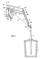
- a steel pan 1 and a diving lance 2 can be seen in the rest position, that is, in the raised position.
- the immersion lance 2 is connected to the device according to the invention via a fixed triangle 11.
- a bracket 3 is rotatably arranged via, for example, ball bearings.
- a hydraulically actuated cylinder 13 is also attached to the console 3 and causes the immersion lance 2 to be raised or lowered. When the immersion lance 2 is in the rest position, the cylinder piston rod 14 is in the extended position.
- An arm 4 is provided on the console 3 itself via an axis 15b, which arm is connected at its upper end to a second arm 5 via a further axis 15g.
- the diving lance holder 11 is articulated via an axis 15j.
- a guide arm 7 engages the piston rod 14 at one end via an axis 15c and is connected to the arm 5 at its other end via a further axis 15h. It should be noted here that the guide arm 7 is absolutely parallel to the arm 4.
- a second guide arm 6 connects the arm 4 to the guide arm 7 via two axes 15d and 15e. The guide arm 6 is also arranged parallel to the arm 5. In order to avoid a possible deviation of the diving lance 2 during the lowering or lifting from the vertical axis, it is necessary that the centers of the axes 15b, 15c and 15j are on an imaginary line 8.
- the two axes 15c and 15e could be designed as a single one, whereby the condition that the guide arm 6 is parallel to the arm 5 must still be fulfilled. This will of course shift the point of attack 15d on the arm 4. For design reasons, however retain the alternative shown in the figures.
- a guide which essentially consists of two guide rods 9 and 10 which are connected to one another via an axis 15f.
- the guide rod 9 is connected at its end opposite the axis 15f to the bracket 3 via an axis 15a and the guide rod 10 is connected to the rope lance holder 11 via an axis 15i.
- the axes 15f and 15g are connected to one another via a connecting member 17. It should also be emphasized that the imaginary lines between the axes 15f and lSg and between the axes 15i and 15j are parallel to the cylinder 13 or the piston rod 14.
- an adaptation device 16 is preferably provided comprising a set screw as a further fastening.
- the rotation of the console 3 with the entire device about the axis 12 can be achieved by a device known per se, for. B. via hydraulic cylinder or electric motor with gear.
- the position of the immersion lance 2 can be displayed continuously, for example via an angle sensor in the axis 15a or 15b.
- Figure 2 shows the diving lance 2 in the working position, i.e. inserted into the steel pan 1. It should be noted here that the piston rod 14 has moved into the cylinder 13. However, the piston rod 14 could easily be brought into any position between the rest and working positions.
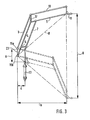
- FIG. 3 shows a schematic representation of the arrangement between the hydraulic cylinder 13 and the immersion lance holder 11.
- the vertical connecting line 23 between the two axes 1Sa and 15b is assumed as the reference line.
- the ratio of the distance a between the hydraulic cylinder 13 and the reference line 23 to the distance b between the lance holder 11 and the reference line 23 is equal to the ratio of the stroke A of the hydraulic cylinder 13 to the stroke B of the submersible lance holder 11
- the optimal conditions between the individual values specified and the force of the hydraulic cylinder can be determined.
- FIG. 4 shows a schematic illustration of the influence of a horizontal displacement of the hydraulic cylinder 13 on the immersion lance holder 11, which is shown only as a line in this figure.
- a displacement of the cylinder 13 from position 13a to position 13b means an increase in the distance to the reference line 23 from a to a le .
- this displacement means a displacement of the distance to the reference line 23 from b to b l .
- the ratio a to a 1 is equal to the ratio b to b 1 .
Abstract
Description
Die vorliegende Erfindung betrifft eine Vorrichtung zum Einblasen von Substanzen in eine Stahlschmelze , insbesondere eine Halterungsund Führungsvorrichtung einer Taucnlanze durch welche die Subscanzen mit Hilfe eines Trägergases in die Stahlschmelze eingebracht wird.The present invention relates to a device for blowing substances into a molten steel, in particular a holding and guiding device of a dew lance through which the subscans are introduced into the molten steel with the aid of a carrier gas.
Es ist seit Jahrzehnten bekannt, Eisenschmelzen dadurch zu entschwefeln, dass mit Hilfe geeigneter Vorrichtungen Substanzen beigesetzt werden, die in der Lage sind, bei hohen Temperaturen und unter reduzierenden Bedingungen mit dem in den Schmelzen enthaltenen Schwefel Verbindungen einzugehen, welche sich in den über den Schmelzen vorhandenen Schmelzschichten absetzen. Solche Produkte sind beispielsweise CaSi, CaC2 oder Gemische aus Ca0 und CaF2. Diese Substanzen werden in Granulatform mit Hilfe eines Trägergases, vorzugsweise Argon, und einer in die Stahlschmelze eingeführten Tauchlanze in dosierten Mengen eingebracht. Ein solches Verfahren und Vorrichtung zum Dosieren werden beispielsweise in den beiden luxemburgischen Patenten 80 692 und 82 977 beschrieben.It has been known for decades to desulfurize iron melts by using suitable devices to add substances which are able to form compounds at high temperatures and under reducing conditions with the sulfur contained in the melts, which compounds are found in the above the melts remove existing enamel layers. Such products are, for example, CaSi, CaC 2 or mixtures of Ca0 and CaF 2 . These substances are introduced in granular form with the aid of a carrier gas, preferably argon, and an immersion lance introduced into the molten steel in metered amounts. Such a method and device for dosing are described for example in the two Luxembourg patents 80 692 and 82 977.
Bei allen bekannten Anlagen wird die Tauchlanze über eine Einrichtung in die Stahlschmelze getaucht bzw. herausgezogen , welche eine senkrecht angeordnete Lafette umfasst die als Führung einer von einem elektrischen Hubwerk gesenkten bzw. gehobenen Tauchlanzen-Halterung ausgebildet ist. Die Lafette an sich ist so angeordnet, dass die Tauchlanze mittig in die Stahlschmelze eingeführt werden kann.In all known systems, the immersion lance is immersed or drawn out into the molten steel by means of a device which comprises a vertically arranged mount which is designed as a guide for an immersion lance holder which is lowered or raised by an electrical lifting mechanism. The carriage itself is arranged so that the immersion lance can be inserted in the middle of the molten steel.
Sämtliche bekannte Einrichtungen besitzen unter anderen den Nachteil, dass sie eine äusserst aufwendige Konstruktion aufweisen müssen, um eine einigermassen exakte Führung gewährleisten zu können. Desweiteren ' ergeben sich durch die lineare Bewegung der Tauchlanzen-Halterung auf der Lafette Toleranzen, welche ein robustes, schwingungsfreies Führen der Tauchlanze nicht gewährleisten. Schwingungen bzw. Schläge an der Tauchlanze werden hervorgerufen durch die im Bad während dem Einblasvorgang bedingten chemischen Reaktionen und übertragen sich bei einer unfachgemässen Führung auf die gesamte Trägerkonstruktion sowie über die Fundamentbefestigungen auf die Hallenkonstruktion.All known devices have the disadvantage, among other things, that they must have an extremely complex construction in order to be able to guarantee a reasonably exact guidance. Furthermore, the linear movement of the immersion lance holder on the carriage results in tolerances which do not guarantee robust, vibration-free guidance of the immersion lance. Vibrations or impacts on the immersion lance are caused by the chemical reactions in the bath during the blowing process and are transferred to the entire support structure as well as to the hall structure if the guide is not properly guided.
Der vorliegenden Erfindung liegt die Aufgabe zugrunde eine Einrichtung vorzuschlagen, welche in der Lage ist, neben einer exakten Führung der Tauchlanze in die Stahlschmelze eine äusserst weitgehende Robustheit vorzuzeigen, welche die durch die chemischen Reaktionen hervorgerufenen Schwingungen aufnimmt.The present invention is based on the object of proposing a device which, in addition to precisely guiding the immersion lance into the molten steel, is able to demonstrate an extremely extensive robustness which absorbs the vibrations caused by the chemical reactions.
Erfindungsgemäss wird das Ziel erreicht durch eine Vorrichtung zum Einblasen von Substanzen in eine Stahlschmelze, insbesondere eine Halterungs. und Führungsvorrichtung einer Tauchlanze durch welche die Substanzen mit Hilfe eines Trägergases in die Stahlschmelze eingebracht werden.According to the invention, the aim is achieved by a device for blowing substances into a molten steel, in particular a holder. and guide device of a submersible lance through which the substances are introduced into the molten steel with the aid of a carrier gas.
Vorzugsweise wird das Heben bzw. Senken der Tauchlanze durch einen an der Konsole senkrecht angeordneten hydraulisch betätigten Zylinder erreicht.The lifting or lowering of the immersion lance is preferably achieved by a hydraulically operated cylinder arranged vertically on the console.
Desweiteren kann die gesamte Vorrichtung um eine senkrecht innerhalb der Konsole angeordnete Achse horizontal geschwenkt werden. Zu diesem Schwenkvorgang ist vorzugsweise ebenfalls ein horizontal angeordneter hydraulisch betätigter Zylinder vorgesehen.Furthermore, the entire device can be pivoted horizontally about an axis arranged vertically within the console. A horizontally arranged hydraulically actuated cylinder is preferably also provided for this pivoting process.
Zur Erläuterung der erfindungsgemässen Vorrichtung und ihrer Betriebsweise wird auf die Zeichnungen und deren Beschreibung verwiesen. Es zeigen :
- Figur 1, eine schematische Seitenansicht einer bevorzugten Ausführung der erfindungsgemässen Vorrichtung in gehobener Stellung ;
Figur 2, eine schematische Seitenansicht der-Vorrichtung in gesenkter Stellung ;Figur 3, eine schematische Seitenansicht, welche die Verhältnisse der Vorrichtung zwischen Senken und Heben darstellt ;- Figur 4, eine schematische Seitenansicht der Vorrichtung welche den Einfluss eines horizontalen Verstellens des Senk- bzw. Hubzylinders darstellt.
- Figure 1 is a schematic side view of a preferred embodiment of the device according to the invention in the raised position;
- Figure 2 is a schematic side view of the device in the lowered position;
- Figure 3 is a schematic side view showing the relationship of the device between lowering and lifting;
- Figure 4 is a schematic side view of the device which illustrates the influence of a horizontal adjustment of the lowering or lifting cylinder.
In Figur 1 ist eine Stahlpfanne 1 und eine Tauchlanze 2 in Ruhestellung das heisst in gehobener Stellung zu erkennen. Die Tauchlanze 2 ist über ein feststehendes Dreieck 11 mit der erfindungsgemässen Vorrichtung verbunden.In Figure 1, a steel pan 1 and a
An einer senkrechten Achse 12 ist eine Konsole 3 über beispielsweise Kugellager drehbar angeordnet. An der Konsole 3 ist ebenfalls ein hydraulisch betätigter Zylinder 13 angebracht, welcher das Heben bzw. Senken der Tauchlanze 2 bewirkt. In Ruhestellung der Tauchlanze 2 befindet sich die Zylinder-Kolbenstange 14 in ausgefahrener Position.On a
An der Konsole 3 selbst ist über eine Achse 15b ein Arm 4 vorgesehen, welcher an seinem oberen Ende über eine weitere Achse 15g mit einem zweiten Arm 5 verbunden ist. Am anderen Ende des Armes 5 ist die Tauchlanzen-Halterung 11 über eine Achse 15j gelenkig angeordnet.An arm 4 is provided on the
Ein Leitarm 7 greift an einem seiner Enden über eine Achse 15c an die Kolbenstange 14 an und ist an seinem anderen Ende über eine weitere Achse 15h mit dem Arm 5 verbunden. Hierbei ist zu beachten, dass der Leitarm 7 absolut parallel zum Arm 4 ist. Ein zweiter Leitarm 6 verbindet über zwei Achsen 15d und 15e den Arm 4 mit dem Leitarm 7. Der Leitarm 6 ist ebenfalls parallel zu dem Arm 5 angeordnet. Um eine eventuelle Abweichung der Tauchlanze 2 während dem Senken bzw. Heben von der senkrechten Achse zu vermeiden, ist es notwendig, dass die Zentren der Achsen 15b, 15c und 15j sich auf einer imaginären Linie 8 befinden.A guide arm 7 engages the
An sich könnten die beiden Achsen 15c und 15e als eine einzige ausgeführt werden, wobei die Bedingung weiterhin erfüllt sein muss, dass der Leitarm 6 parallel zum Arm 5 ist. Hierdurch wird sich natürlich der Angriffspunkt 15d am Arm 4 verschieben. Aus konstruktiven Gründen wurde jedoch die in den Figuren dargestellten Alternative zurückbehalten.As such, the two
Damit die Tauchlanze. 2 in ihrer absolut senkrechten Anordnung beim Heben bzw. Senken verbleibt , ist es empfehlenswert, eine Führung anzubringen welche im wesentlichen aus zwei Führungsstangen 9 und 10 welche über eine Achse 15f miteinander verbunden sind, besteht. Hierbei ist die Führungsstange 9 an ihrem der Achse 15f entgegengesetzten Ende über eine Achse 15a mit der Konsole 3 verbunden und die Führungsstange 10 über eine Achse 15i mit der Taucnlanzen-Halterung 11.So that the diving lance. 2 remains in its absolutely vertical arrangement when lifting or lowering, it is advisable to attach a guide which essentially consists of two
Um eine absolute Parallelität zu gewährleisten, werden die Achsen 15f und 15g über ein Verbindungsglied 17 miteinander verbunden. Es sei noch hervorgehoben, dass die gedachten Linien zwischen den Achsen 15f und lSg und zwischen den Achsen 15i und 15j parallel zum Zylinder 13 bzw. der Kolbenstange 14 sind.In order to ensure absolute parallelism, the
Um eventuelle Herstellungstoleranzen auszugleichen, kann der Zylinder 13 in seiner Aufhängung 18 verstellt und anschliessend in der gewünschten Lage blockiert werden. Aus demselben Grund ist eine Anpassungsvorrichtung 16 vorzugsweise eine Stellschraube umfassend als weitere Befestigung vorgesehen.In order to compensate for any manufacturing tolerances, the
Die Drehung der Konsole 3 mit der gesamten Vorrichtung um die Achse 12 kann durch eine an sich bekannte Vorrichtung erreicht werden, so z. B. über Hydraulikzylinder oder Elektromotor mit Getriebe.The rotation of the
Desweiteren kann die Stellung der Tauchlanze 2 beispielsweise über einen Winkelgeber in der Achse 15a oder 15b kontinuierlich angezeigt werden.Furthermore, the position of the
Die Figur 2 zeigt die Tauchlanze 2 in Arbeitsstellung d.h. in die Stahlpfanne 1 eingeführt. Hierbei ist zu beachten, dass die Kolbenstange 14 in den Zylinder 13 eingefahren ist. Jedoch könnte die Kolbenstange 14 ohne weiteres in jede beliebige Stellung zwischen Ruhe-und Arbeitsstellung gebracht werden.Figure 2 shows the
Figur 3 zeigt in schematischer Darstellung die anordnungsgemässen Verhältnisse zwischem dem Hydraulikzylinder 13 und der Tauchlanzen-Halterung 11. Als Referenzlinie sei die vertikale Verbindungslinie 23 zwischem den beiden Achsen 1Sa und 15b angenommen. Das Verhältnis des Abstandes a des Hydraulikzylinders 13 gegenüber der Referenzlinie 23 zum Abstand b der Lanzen-Halterung 11 gegenüber der Referenzlinie 23 ist gleich dem Verhältnis des Hubes A des Hydraulikzylinders 13 zum Hub B der Tauchlanzen-Halterung 11. Aus dem Grunde können für jede bestimmte Anlage die optimalen Bedingungen zwischen den einzelnen angegebenen Werten und der Kraft des Hydraulikzylinders ermittelt werden.FIG. 3 shows a schematic representation of the arrangement between the
Figur 4 zeigt in schematischer Darstellung den Einfluss einer waagerechten Verschiebung des Hydraulikzylinders 13 auf die Tauchlanzen-Halterung 11, welche auf dieser Figur nur als Linie dargestellt ist.FIG. 4 shows a schematic illustration of the influence of a horizontal displacement of the
Ein Versetzen des Zylinders 13 von Position 13a nach Position 13b bedeutet eine Vergrösserung des Abstandes zur Referenzlinie 23 von a zu ale Dieses Versetzen bedeutet für die Lanzenführung 11 eine Verschiebung des Abstandes zur Referenzlinie 23 von b zu bl. Das Verhältnis a zu a1 ist gleich dem Verhältnis b zu b1.A displacement of the
Claims (8)
Priority Applications (1)
| Application Number | Priority Date | Filing Date | Title |
|---|---|---|---|
| AT82100134T ATE8665T1 (en) | 1981-01-26 | 1982-01-11 | DEVICE FOR INJECTING SUBSTANCES INTO MELTED STEEL. |
Applications Claiming Priority (2)
| Application Number | Priority Date | Filing Date | Title |
|---|---|---|---|
| LU83090 | 1981-01-26 | ||
| LU83090A LU83090A1 (en) | 1981-01-26 | 1981-01-26 | DEVICE FOR INJECTING PRODUCTS INTO THE STEEL MELT |
Publications (3)
| Publication Number | Publication Date |
|---|---|
| EP0056944A2 true EP0056944A2 (en) | 1982-08-04 |
| EP0056944A3 EP0056944A3 (en) | 1982-08-18 |
| EP0056944B1 EP0056944B1 (en) | 1984-07-25 |
Family
ID=19729573
Family Applications (1)
| Application Number | Title | Priority Date | Filing Date |
|---|---|---|---|
| EP82100134A Expired EP0056944B1 (en) | 1981-01-26 | 1982-01-11 | Installation for injecting materials into a steel melt |
Country Status (5)
| Country | Link |
|---|---|
| EP (1) | EP0056944B1 (en) |
| AT (1) | ATE8665T1 (en) |
| AU (1) | AU7929282A (en) |
| DE (1) | DE3260409D1 (en) |
| LU (1) | LU83090A1 (en) |
Cited By (1)
| Publication number | Priority date | Publication date | Assignee | Title |
|---|---|---|---|---|
| CN102756119A (en) * | 2012-07-14 | 2012-10-31 | 马鞍山市博威液压机械制造有限责任公司 | Pole telescopic type hydraulic skimmer |
Citations (6)
| Publication number | Priority date | Publication date | Assignee | Title |
|---|---|---|---|---|
| US3063699A (en) * | 1960-12-01 | 1962-11-13 | Robert C Read | Mobile apparatus for lancing molten mixtures |
| US3342471A (en) * | 1964-06-22 | 1967-09-19 | Kaiser Ind Corp | Oxygen lance assembly |
| US3358985A (en) * | 1964-04-17 | 1967-12-19 | Nat Steel Corp | Apparatus for conveying fluid toward a region of high temperature |
| US3891196A (en) * | 1974-01-21 | 1975-06-24 | Thyssen Niederrhein Ag | Apparatus for treating a melt |
| AT336900B (en) * | 1974-04-04 | 1977-05-25 | Vmw Ranshofen Berndorf Ag | DEVICE FOR INTRODUCING GASES IN LIQUIDS, IN PARTICULAR MELTS |
| EP0013550A1 (en) * | 1978-12-21 | 1980-07-23 | Arbed S.A. | Process and apparatus for the desulphurisation of molten ferrous metals |
-
1981
- 1981-01-26 LU LU83090A patent/LU83090A1/en unknown
-
1982
- 1982-01-08 AU AU79292/82A patent/AU7929282A/en not_active Abandoned
- 1982-01-11 EP EP82100134A patent/EP0056944B1/en not_active Expired
- 1982-01-11 DE DE8282100134T patent/DE3260409D1/en not_active Expired
- 1982-01-11 AT AT82100134T patent/ATE8665T1/en not_active IP Right Cessation
Patent Citations (6)
| Publication number | Priority date | Publication date | Assignee | Title |
|---|---|---|---|---|
| US3063699A (en) * | 1960-12-01 | 1962-11-13 | Robert C Read | Mobile apparatus for lancing molten mixtures |
| US3358985A (en) * | 1964-04-17 | 1967-12-19 | Nat Steel Corp | Apparatus for conveying fluid toward a region of high temperature |
| US3342471A (en) * | 1964-06-22 | 1967-09-19 | Kaiser Ind Corp | Oxygen lance assembly |
| US3891196A (en) * | 1974-01-21 | 1975-06-24 | Thyssen Niederrhein Ag | Apparatus for treating a melt |
| AT336900B (en) * | 1974-04-04 | 1977-05-25 | Vmw Ranshofen Berndorf Ag | DEVICE FOR INTRODUCING GASES IN LIQUIDS, IN PARTICULAR MELTS |
| EP0013550A1 (en) * | 1978-12-21 | 1980-07-23 | Arbed S.A. | Process and apparatus for the desulphurisation of molten ferrous metals |
Cited By (2)
| Publication number | Priority date | Publication date | Assignee | Title |
|---|---|---|---|---|
| CN102756119A (en) * | 2012-07-14 | 2012-10-31 | 马鞍山市博威液压机械制造有限责任公司 | Pole telescopic type hydraulic skimmer |
| CN102756119B (en) * | 2012-07-14 | 2014-06-11 | 马鞍山市博威液压机械制造有限责任公司 | Pole telescopic type hydraulic skimmer |
Also Published As
| Publication number | Publication date |
|---|---|
| EP0056944A3 (en) | 1982-08-18 |
| AU7929282A (en) | 1982-08-05 |
| LU83090A1 (en) | 1982-09-10 |
| DE3260409D1 (en) | 1984-08-30 |
| EP0056944B1 (en) | 1984-07-25 |
| ATE8665T1 (en) | 1984-08-15 |
Similar Documents
| Publication | Publication Date | Title |
|---|---|---|
| DE2544525B2 (en) | Mobildrehkan | |
| EP0814052A1 (en) | Mobile working platform | |
| DE3721673C2 (en) | Device on the cab of a crane | |
| DE3139490A1 (en) | UNIVERSAL ROBOT | |
| DE2821113A1 (en) | METHOD AND DEVICE FOR MACHINE ADJUSTMENT OF THE INCLINATION OF A ROCK DRILLING DEVICE | |
| DE3220744A1 (en) | Melting and casting plant for vacuum or protective gas operation with at least two chambers | |
| EP0112540A1 (en) | Installation for guiding and changing immersion lances | |
| EP0056944B1 (en) | Installation for injecting materials into a steel melt | |
| DE10026098A1 (en) | Device for the automatic removal of objects from containers | |
| DE2509805A1 (en) | TUBE HOLE DRILLING OR PLUGGING MACHINE FOR MANHOLE, IN PARTICULAR BIG FURNACES | |
| EP0056942B1 (en) | Installation for the holding and changing of immersion lances | |
| DE2419359A1 (en) | SUPPORT PLATFORM FOR LOADS | |
| DE19620986C1 (en) | Suspension device for travelling stirrer | |
| DE3149889C2 (en) | Device for the actuation of manual transmissions for experimental purposes | |
| DE2700284A1 (en) | DEVICE FOR TRANSPORTING PARTICULAR SMALL OBJECTS IN ALL DIRECTIONS | |
| DE3147127A1 (en) | Apparatus for operating electrolysers employing pre-baked anodes | |
| DE3026711C2 (en) | Drive device for the mixing drum of a transport concrete mixer during the loading process | |
| DE3231024A1 (en) | Release device for aircraft external loads | |
| DE2158484B2 (en) | Elastic support for a tiltable driver's cab of a truck | |
| DE3505435C2 (en) | ||
| EP0006224B1 (en) | Device for introducing from the top a dummy bar into a continuous-casting plant | |
| DE2307183C3 (en) | Pedal assembly, especially for armored vehicles | |
| EP0284808A2 (en) | Electric-discharge machine | |
| DE3827410A1 (en) | Coordinate measuring machine | |
| DE3416628A1 (en) | TRANSMISSION REMOTE CONTROL FOR COMMERCIAL VEHICLES |
Legal Events
| Date | Code | Title | Description |
|---|---|---|---|
| PUAI | Public reference made under article 153(3) epc to a published international application that has entered the european phase |
Free format text: ORIGINAL CODE: 0009012 |
|
| PUAL | Search report despatched |
Free format text: ORIGINAL CODE: 0009013 |
|
| AK | Designated contracting states |
Designated state(s): AT BE DE FR GB IT NL |
|
| AK | Designated contracting states |
Designated state(s): AT BE DE FR GB IT NL |
|
| 17P | Request for examination filed |
Effective date: 19821115 |
|
| ITF | It: translation for a ep patent filed |
Owner name: MODIANO & ASSOCIATI S.R.L. |
|
| GRAA | (expected) grant |
Free format text: ORIGINAL CODE: 0009210 |
|
| AK | Designated contracting states |
Designated state(s): AT BE DE FR GB IT NL |
|
| REF | Corresponds to: |
Ref document number: 8665 Country of ref document: AT Date of ref document: 19840815 Kind code of ref document: T |
|
| REF | Corresponds to: |
Ref document number: 3260409 Country of ref document: DE Date of ref document: 19840830 |
|
| ET | Fr: translation filed | ||
| PLBE | No opposition filed within time limit |
Free format text: ORIGINAL CODE: 0009261 |
|
| STAA | Information on the status of an ep patent application or granted ep patent |
Free format text: STATUS: NO OPPOSITION FILED WITHIN TIME LIMIT |
|
| 26N | No opposition filed | ||
| ITTA | It: last paid annual fee | ||
| PGFP | Annual fee paid to national office [announced via postgrant information from national office to epo] |
Ref country code: FR Payment date: 19921204 Year of fee payment: 12 |
|
| PGFP | Annual fee paid to national office [announced via postgrant information from national office to epo] |
Ref country code: DE Payment date: 19921215 Year of fee payment: 12 |
|
| PGFP | Annual fee paid to national office [announced via postgrant information from national office to epo] |
Ref country code: GB Payment date: 19930108 Year of fee payment: 12 |
|
| PGFP | Annual fee paid to national office [announced via postgrant information from national office to epo] |
Ref country code: AT Payment date: 19930131 Year of fee payment: 12 Ref country code: NL Payment date: 19930131 Year of fee payment: 12 |
|
| PGFP | Annual fee paid to national office [announced via postgrant information from national office to epo] |
Ref country code: BE Payment date: 19930215 Year of fee payment: 12 |
|
| PG25 | Lapsed in a contracting state [announced via postgrant information from national office to epo] |
Ref country code: AT Effective date: 19940111 Ref country code: GB Effective date: 19940111 |
|
| PG25 | Lapsed in a contracting state [announced via postgrant information from national office to epo] |
Ref country code: BE Effective date: 19940131 |
|
| BERE | Be: lapsed |
Owner name: PAUL WURTH S.A. Effective date: 19940131 |
|
| PG25 | Lapsed in a contracting state [announced via postgrant information from national office to epo] |
Ref country code: NL Effective date: 19940801 |
|
| GBPC | Gb: european patent ceased through non-payment of renewal fee |
Effective date: 19940111 |
|
| NLV4 | Nl: lapsed or anulled due to non-payment of the annual fee | ||
| PG25 | Lapsed in a contracting state [announced via postgrant information from national office to epo] |
Ref country code: FR Effective date: 19940930 |
|
| PG25 | Lapsed in a contracting state [announced via postgrant information from national office to epo] |
Ref country code: DE Effective date: 19941001 |
|
| REG | Reference to a national code |
Ref country code: FR Ref legal event code: ST |