EP0053970A1 - Means for the directional connection of tubular scaffolding elements - Google Patents
Means for the directional connection of tubular scaffolding elements Download PDFInfo
- Publication number
- EP0053970A1 EP0053970A1 EP81401879A EP81401879A EP0053970A1 EP 0053970 A1 EP0053970 A1 EP 0053970A1 EP 81401879 A EP81401879 A EP 81401879A EP 81401879 A EP81401879 A EP 81401879A EP 0053970 A1 EP0053970 A1 EP 0053970A1
- Authority
- EP
- European Patent Office
- Prior art keywords
- flange
- radial
- ring
- arm
- key
- Prior art date
- Legal status (The legal status is an assumption and is not a legal conclusion. Google has not performed a legal analysis and makes no representation as to the accuracy of the status listed.)
- Granted
Links
Images


Classifications
-
- E—FIXED CONSTRUCTIONS
- E04—BUILDING
- E04G—SCAFFOLDING; FORMS; SHUTTERING; BUILDING IMPLEMENTS OR AIDS, OR THEIR USE; HANDLING BUILDING MATERIALS ON THE SITE; REPAIRING, BREAKING-UP OR OTHER WORK ON EXISTING BUILDINGS
- E04G7/00—Connections between parts of the scaffold
- E04G7/30—Scaffolding bars or members with non-detachably fixed coupling elements
- E04G7/302—Scaffolding bars or members with non-detachably fixed coupling elements for connecting crossing or intersecting bars or members
- E04G7/306—Scaffolding bars or members with non-detachably fixed coupling elements for connecting crossing or intersecting bars or members the added coupling elements are fixed at several bars or members to connect
- E04G7/307—Scaffolding bars or members with non-detachably fixed coupling elements for connecting crossing or intersecting bars or members the added coupling elements are fixed at several bars or members to connect with tying means for connecting the bars or members
-
- E—FIXED CONSTRUCTIONS
- E04—BUILDING
- E04G—SCAFFOLDING; FORMS; SHUTTERING; BUILDING IMPLEMENTS OR AIDS, OR THEIR USE; HANDLING BUILDING MATERIALS ON THE SITE; REPAIRING, BREAKING-UP OR OTHER WORK ON EXISTING BUILDINGS
- E04G7/00—Connections between parts of the scaffold
- E04G7/30—Scaffolding bars or members with non-detachably fixed coupling elements
- E04G7/32—Scaffolding bars or members with non-detachably fixed coupling elements with coupling elements using wedges
-
- Y—GENERAL TAGGING OF NEW TECHNOLOGICAL DEVELOPMENTS; GENERAL TAGGING OF CROSS-SECTIONAL TECHNOLOGIES SPANNING OVER SEVERAL SECTIONS OF THE IPC; TECHNICAL SUBJECTS COVERED BY FORMER USPC CROSS-REFERENCE ART COLLECTIONS [XRACs] AND DIGESTS
- Y10—TECHNICAL SUBJECTS COVERED BY FORMER USPC
- Y10T—TECHNICAL SUBJECTS COVERED BY FORMER US CLASSIFICATION
- Y10T403/00—Joints and connections
- Y10T403/30—Laterally related members connected by latch means, e.g., scaffold connectors
Definitions
- the present invention relates to a directional assembly device between the elements, in particular tubular, of a scaffolding. More particularly, it relates to such a device adapted to connect fixedly, rigidly and in a determined direction, horizontal elements, such as crosspieces, beams, beams and diagonals, on vertical elements, such as uprights and posts, in order to form a knot. where the forces transmitted by the horizontal elements arrive at a common point located in the center of the vertical elements and without producing any moment of gyration on them.
- the directional assembly device between the tubular elements, of a scaffolding for example which is the subject of the present invention, is designed so as to eliminate the aforementioned drawbacks of the known assembly devices, by ensuring stability directional determined to the horizontal elements with respect to the vertical elements and vice versa, both in a horizontal plane and in a vertical plane, this directional stability being obtained from the start of assembly without requiring, for example, checking the squareness of the elements between them at the location of the nodes and / or play, during assembly, on the orientation of these elements before permanently locking them in position by acting on the keyways.
- such an assembly device between the horizontal and vertical elements of a tubular scaffolding is constituted by a ring carrying four radial arms, at right angles to one another , engaged on a vertical element, each arm being adapted to engage in a flange, integral with the end of the corresponding horizontal element and provided with bosses intended to bear on the ring, on either side of the arm considered, in order to provide this horizontal element with an exact direction in the extension of this arm, this flange being blocked on the latter by the forced insertion of a key in diametrically opposite openings, the end of which horizontal element is provided behind the flange, this key passing through, between these openings, a corresponding rectangular hole located in the engaged arm of the ring.
- each flange has a central bore, adapted to allow the partial fitting of the corresponding end of the element which carries it fixed by welding, this flange being provided, on the side opposite to its support bosses, with two diametrically opposite notches and corresponding to the rectangular key engagement openings at the end of the element, the bottom of these notches being adapted to serve as support for the face of the key which pushes this flange towards said assembly ring , when the other opposite face of this force-fitted key comes into contact with the outside width side of the hole in the radial arm engaged in this flange.
- each flange is provided so that its lateral bosses respectively bear on the corresponding sides of the radial arms situated on either side of the arm on which this flange is engaged, thereby providing the latter with a more substantial support seat on the ring and, consequently, an exact orientation in the extension of the engaged arm.
- the present invention provides another flange design, integral with the corresponding end of this cross member, this flange carrying lateral bosses, adapted to bear on the corresponding side of the bosses of the flanges of the mounted elements and comprising two diametrically opposite front projections, designed to engage respectively on the top and the bottom of the arm in question and provided with openings d 'Key engagement, similar to those of the ends of the other elements and arranged to cooperate in the same way with the rectangular hole in the arm.
- the assembly ring is provided, between its radial arms, with intermediate external ribs, the peripheral edge of which is designed to receive the bosses of each flange in support and provide the latter ci, as well as the horizontal element which carries it, a direction of fixing exactly in the axial extension of the radial arm which is engaged in this flange.
- each rib part between two arms can be provided, optionally, with a cylindrical hole suitable for the forced introduction of a conical pin for fixing a yoke end of the diagonal or triangulation bar.
- the assembly ring is in the form of a star, each branch of which constitutes a radial arm provided with a radial V-shaped recess and lateral bosses at this recess, designed in the form of steps and adapted to receive the support from the front end of said flange or yoke engaged on this arm and secured to the corresponding radial tubular element, these support steps being provided on the two faces, upper and lower , of each branch or arm and over a width and a. sufficient thickness, determined so as to ensure a substantial seat at the end of said flange and directional stability to the radial tubular element, both in a vertical plane and in a horizontal plane, during the keying operation of the 'assembly.
- each branch is provided on its lower face with a single step-shaped boss, while its upper face has two successive bosses forming two steps, this arrangement being designed to allow a certain movement in the vertical plane to the radial tubular element during engagement and cause automatic tilting in the depressed position of the captive key carried by the flange or yoke of this element.
- each flange consists of two L-shaped elements fixed together by the edge of their small wing, the edge of their large wing being adapted to the shape of the corresponding step of the ring to come into abutment. stable on the latter.
- one of the L-shaped elements has a flat key penetration recess closed on its four sides, while, in the other element, the corresponding recess opens into the small wing, in order to allow the introduction of the tip end of the key provided slightly swollen and make it captive of this element when the flange formed by these two elements will be fixed in manufacture on the end of the radial tubular element.
- the flange element having the recess opening into its small wing is provided with an internal cavity corresponding to the bulge of the tip end of the captive key and allowing the latter to be retracted during the 'engagement of the flange on a branch of the ring, this flange element being engaged on the steps of the upper face of this branch.
- the device for assembling tubular elements consists of a ring 1 provided with four radial arms 2, arranged at right angles to each other. other, this ring 1 being engaged on a vertical tubular element 3 and each arm being adapted to engage in a flange 4 (shown in section in FIG. 1), integral with the end of a horizontal tubular element 5 (shown dotted for easier understanding).
- This flange 4 is provided with lateral bosses 6, designed to bear on the body of the ring 1, or on the corresponding side of the radial arms 2 (as shown in FIG. 1) located on either side of the arm fitted in the flange end of the horizontal tubular element 5 considered.
- This flange is locked in the support position by means of a key (not shown) engaged in the diametrically opposite openings 7,8 made in the end of the horizontal element 5 behind the flange 4, this key crossing between these openings 7,8 a rectangular hole 9 with which each radial arm 2 is provided.
- the ring 1 has a flared bore at its two opposite ends 10,11 and adapted for its fixing by welding on the vertical tubular element 3, or for its positioning in fixed position, although pivoting, on this element 3 by means of a frustoconical ring (not shown), welded on the latter and whose upper end, of smaller diameter, can engage in the lower flared end 11 of the ring 1.
- the flange 4 has a central bore 12, adapted to allow the partial fitting of the end of the tubular element 5 and the fixing by welding of the flange on the latter.
- This flange further comprises, on the side opposite to its bosses 6, that is to say on the side of the element 5, two notches 13, diametrically opposite and corresponding to the rectangular openings 7,8 for key fitting and , thereby, to the rectangular hole 9 of the radial arm 2.
- the bottom of these notches is adapted to serve as a support for the face of the key which pushes the flange 4 towards the ring 1, when the other opposite face of this key is in contact with the outer edge 14 of the rectangular hole 9.
- This flange 15 fixed identically to that of the other flanges 4 at the end of a tubular element 16, is provided with lateral bosses 17, adapted to bear on the side of the bosses 6 of the other flanges 4, and comprises two diametrically opposite front projections 18, 19, framing the top and the bottom of the radial arm 2 engaged in it, and provided with key engagement openings 20 (shown in dotted lines in FIG. 1) similar and of the same arrangement as those of ends of other elements 5.
- the assembly ring 1 is provided, between its radial arms 2, with angular external ribs 21, the edges of which serve to support the lateral bosses 22 of the flanges carried by tubular elements 23.
- these flanges are designed in the same way as the flanges 4 (of FIG. 1), except that their bosses 22 are less apart laterally and less prominent than the bosses 6 of these flanges.
- This assembly arrangement makes it possible to mount four horizontal elements perpendicular to each other on the same ring, without their identical flanges interfering with each other.
- each support rib 21 has a cylindrical hole 24, suitable for the forced introduction of a conical pin for fixing a yoke end of the diagonal or triangulation bar.
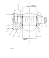
- the ring 31, shown in FIGS. 4 and 5, engaged and fixed on a vertical tubular element 32 is in the form of a star with four branches 33 each of which constitutes a radial arm adapted to receive the engagement of a flange or yoke 34, shown in FIGS. 6 to 8, the assembly being blocked, as can be seen in better in FIG. 9, by means of a flat key 35.
- Each branch 33 of the ring is provided with a V-shaped radial recess 36, opening out by its flaring on the outer wall of the tube 32.
- Each branch 33 comprises also, on either side of its recess 36, lateral bosses 37, 38, 39, designed in the form of steps and adapted to receive the support of the front ends 40, 41 of the flange 34, integral with the element radial tubular 42.
- these support steps are t provided on the two upper 43 and lower 44 faces of each branch 33, over a thickness and a sufficient and determined width to ensure a substantial seat at the corresponding ends 40, 41 of the flange 34 and a directional stability to the radial tubular element 42, both in a vertical plane and in a horizontal plane, during the key locking operation 35,
- the ring 31, as best seen in Figure 5, is fixed to the vertical tubular element 32 at several radial points provided by the intermediate sectors 45,46,47,48 to the radial recesses 36 of the branches 33 of this ring.
- the bosses or steps of flange support provided on each branch 33 are distributed so that there are two steps 37,38 on the upper face 43 and a single step 39 on the lower face 44 of this branch, this arrangement being adopted to allow the radial tubular element 42, during engagement, a certain movement in the plane vertical and cause the automatic keying of the captive key 35 into the recess 36 of the branch 33 and its penetration following in the lower recess of the flange 34.
- each flange or yoke 34 consists of two L-shaped elements 49.50 fixed together by the edge of their small wing 51, the edge of their large wing being adapted to the shape of the corresponding step 37,39 of the branch 33, to come into firm and stable support on these steps.
- the lower element 50 comprises a recess 52 for penetrating the end of the key tip 35, closed on its four sides, while the upper element 49 comprises a recess 53 opening into the small wing 51, in order to allow the introduction of the key 35, the tip end of which is swollen laterally, and making it captive when the flange 34 formed by these two elements will be fixed during manufacture to the end of the radial tubular element 42.
- the upper element 49 further comprises an internal cavity 54 corresponding to its recess 52 and having a width sufficient to accommodate the point bulge of the key and retract it when the flange engages on the branch 33 chosen from the ring 31.
Abstract
Un tel dispositif comprend une bague (31) à bras radiaux (33) fixée sur un élément tubulaire vertical (32), une bride ou chape (34) adaptée pour être engagée sur un bras radial et une clavette (35) de verrouillage de l'ensemble. Dans ce dispositif, ladite bague (31) est sous forme d'une étoile dont chaque branche constitue un bras radial (33) pourvu d'un évidement radial (36) en V et de bossages latéraux (37, 38, 39) à cet évidement, conçus sous forme de gradins et adaptés pour recevoir l' appui de l'extrémité frontale de ladite bride ou chape engagée sur ce bras et solidaire de l'élément tubulaire radial (42) correspondant, ces gradins d'appui étant prévus sur les deux faces, supérieure (43) et inférieure (44), de chaque branche ou bras et sur une largeur et une épaisseur suffisante, déterminée de façon à assurer une assise importante à l'extrémité de ladite bride et une stabilité directionnelle à l'élément tubulaire radial, aussi bien dans un plan vertical que dans un plan horizontal, lors de l'opération de clavetage de l'assemblage.Such a device comprises a ring (31) with radial arms (33) fixed on a vertical tubular element (32), a flange or yoke (34) adapted to be engaged on a radial arm and a key (35) for locking the 'together. In this device, said ring (31) is in the form of a star, each branch of which constitutes a radial arm (33) provided with a V-shaped radial recess (36) and lateral bosses (37, 38, 39) at this point. recess, designed in the form of steps and adapted to receive support from the front end of said flange or yoke engaged on this arm and integral with the corresponding radial tubular element (42), these support steps being provided on the two faces, upper (43) and lower (44), of each branch or arm and over a sufficient width and thickness, determined so as to ensure a substantial seat at the end of said flange and directional stability to the element radial tubular, both in a vertical plane and in a horizontal plane, during the keying operation of the assembly.
Description
La présente invention concerne un dispositif d'assemblage directionnel entre les éléments, notamment tubulaires, d'un échafaudage. Plus particulièrement, elle concerne un tel dipositif adapté pour relier fixement, rigidement et suivant une direction déterminée, des éléments horizontaux, tels que traverses, lisses, longrines et diagonales, sur des éléments verticaux, tels que montants et poteaux, afin de former un noeud où les efforts transmis par les éléments horizontaux arrivent en un point commun situé au centre des éléments verticaux et sans produire sur ceux-ci un quelconque moment de giration.The present invention relates to a directional assembly device between the elements, in particular tubular, of a scaffolding. More particularly, it relates to such a device adapted to connect fixedly, rigidly and in a determined direction, horizontal elements, such as crosspieces, beams, beams and diagonals, on vertical elements, such as uprights and posts, in order to form a knot. where the forces transmitted by the horizontal elements arrive at a common point located in the center of the vertical elements and without producing any moment of gyration on them.
Dans la technique de construction des échafaudages tubulaires, on connaît de nombreux types d'assemblages sous forme, par exemple, de colliers ouvrants, fermés et verrouillés sur les tubes par boulons ou clavettes, et montés par paires de manière pivotante d'un collier sur l'autre, ce qui provoque un déport dans la transmission des efforts aux noeuds d'assemblage et, par là, des moments de giration sur les tubes assemblés. D'autres assemblages connus utilisent des emmanchements par coins ou clavettes, solidaires de l'extrémité des éléments horizontaux, s'engageant dans des logements radiaux correspondants de manchons solidaires des éléments verticaux. Des assemblages connus plus récemment dans la technique utilisent, en lieu et place de ces manchons, des disques circulaires pourvus d'ouvertures radiales, sur lesquels sont enclenchées des chapes fendues, solidaires des extrémités des éléments horizontaux ou diagonaux et traversées, ainsi que les ouvertures correspondantes des disques, par des clavettes qui forcent ces chapes à s'appuyer par leur extrémité frontale sur l'extérieur de la paroi des éléments verticaux, afin de fournir un assemblage bloqué. Les deux derniers types d'assemblages qui viennent d'être définis tendent à supprimer les moments de giration qui étaient l'un des inconvénients majeurs des assemblages antérieurs par colliers, mais ne fournissent pas, pour autant, une stabilité directionnelle aux éléments horizontaux lors de leur montage, ce qui peut être considéré comme un défaut important par les utilisateurs et/ou les monteurs d'échafaudages, car ils sont contraints, de ce fait, de vérifier l'équerrage des éléments entre eux à l'emplacement des noeuds et de jouer en cours d'assemblage, par exemple, sur les appuis au sol ou en façade des constructions pour lesquelles ces échafaudages sont nécessaires.In the technique of constructing tubular scaffolds, numerous types of assemblies are known in the form, for example, of opening collars, closed and locked on the tubes by bolts or keys, and pivotally mounted in pairs by a collar on the other, which causes an offset in the transmission of forces to the assembly nodes and, thereby, moments of gyration on the assembled tubes. Other known assemblies use shanks by wedges or keys, integral with the end of the horizontal elements, engaging in corresponding radial housings with sleeves integral with the vertical elements. Known assemblies more recently in the art use, instead of these sleeves, circular discs provided with radial openings, on which are split clevis, integral with the ends of the horizontal or diagonal and crossed elements, as well as the corresponding openings of the discs, by keys which force these yokes to bear by their front end on the outside of the wall of the vertical elements, in order to provide a blocked assembly. The last two types of assemblies which have just been defined tend to eliminate the moments of gyration which were one of the major drawbacks of previous assemblies by collars, but do not however provide directional stability to the horizontal elements during their assembly, which can be considered as a major defect by users and / or scaffolders, because they are forced, therefore, to check the squareness of the elements between them at the location of the nodes and play during assembly, for example, on the supports on the ground or on the facade of constructions for which these scaffolds are necessary.
En conséquence, le dispositif d'assemblage directionnel entre les éléments tubulaires, d'un échafaudage par exemple, faisant l'objet de la présente invention, est conçu de façon à éliminer les inconvénients précités des dispositifs d'assemblage connus, en assurant une stabilité directionnelle déterminée aux éléments horizontaux par rapport aux éléments verticaux et inversement, aussi bien dans un plan horizontal que dans un plan vertical, cette stabilité directionnelle étant obtenue dès le début du montage sans nécessiter, par exemple, la vérification de l'équerrage des éléments entre eux à l'emplacement des noeuds et/ou de jouer, en cours d'assemblage, sur l'orientation de ces éléments avant de les bloquer définitivement en position en agissant sur les clavetages.Consequently, the directional assembly device between the tubular elements, of a scaffolding for example, which is the subject of the present invention, is designed so as to eliminate the aforementioned drawbacks of the known assembly devices, by ensuring stability directional determined to the horizontal elements with respect to the vertical elements and vice versa, both in a horizontal plane and in a vertical plane, this directional stability being obtained from the start of assembly without requiring, for example, checking the squareness of the elements between them at the location of the nodes and / or play, during assembly, on the orientation of these elements before permanently locking them in position by acting on the keyways.
Selon l'invention, dans un mode de réalisation, un tel dispositif d'assemblage entre les éléments horizontaux et verticaux d' un échafaudage tubulaire est constitué par une bague portant quatre bras radiaux, d'équerre l'un par rapport à l'autre, engagée sur un élément vertical, chaque bras étant adapté pour s' engager dans une bride, solidaire de l'extrémité de l'élément horizontal correspondant et pourvue de bossages prévus pour prendre appui sur la bague, de part et d'autre du bras considéré, afin de fournir à cet élément horizontal une direction exacte dans le prolongement de ce bras, cette bride se trouvant bloquée sur ce dernier par l'introduction à force d'une clavette dans des ouvertures diamétralement opposées, dont l'extrémité de l'élément horizontal est pourvue en arrière de la bride, cette clavette traversant, entre ces ouvertures, un trou rectangulaire correspondant situé dans le bras engagé de la bague. Par ailleurs, chaque bride comporte un alésage central, adapté pour permettre l'emmanchement partiel de l'extrémité correspondante de l'élément qui la porte fixée par soudure, cette bride étant pourvue, du côté opposé à ses bossages d'appui, de deux encoches diamétralement opposées et correspondant aux ouvertures rectangulaires d'engagement de clavette de l'extrémité de l'élément, le fond de ces encoches étant adapté pour servir d'appui à la face de la clavette qui repousse cette bride vers ladite bague d'assemblage, quand l'autre face opposée de cette clavette emmanchée à force entre en contact avec le côté largeur extérieur du trou du bras radial engagé dans cette bride. De plus, les ouvertures diamétralement opposées de l'extrémité considérée de l'élément horizontal et situées en correspondance avec les encoches de la bride sont de dimensions différentes, l'ouverture supérieure, ou côté engagement de la pointe de la clavette, ayant une largeur ainsi qu'une longueur supérieures à celles de l'ouverture inférieure, mais sa largeur étant toutefois correspondante à celle du fond de chaque encoche. En outre, chaque bride est prévue de manière que ses bossages latéraux prennent respectivement appui sur les côtés correspondants des bras radiaux situés de part et d'autre du bras sur lequel cette bride est engagée, en fournissant ainsi à celle-ci une assise d'appui plus conséquente sur la bague et, par suite, une orientation exacte dans le prolongement du bras engagé.According to the invention, in one embodiment, such an assembly device between the horizontal and vertical elements of a tubular scaffolding is constituted by a ring carrying four radial arms, at right angles to one another , engaged on a vertical element, each arm being adapted to engage in a flange, integral with the end of the corresponding horizontal element and provided with bosses intended to bear on the ring, on either side of the arm considered, in order to provide this horizontal element with an exact direction in the extension of this arm, this flange being blocked on the latter by the forced insertion of a key in diametrically opposite openings, the end of which horizontal element is provided behind the flange, this key passing through, between these openings, a corresponding rectangular hole located in the engaged arm of the ring. Furthermore, each flange has a central bore, adapted to allow the partial fitting of the corresponding end of the element which carries it fixed by welding, this flange being provided, on the side opposite to its support bosses, with two diametrically opposite notches and corresponding to the rectangular key engagement openings at the end of the element, the bottom of these notches being adapted to serve as support for the face of the key which pushes this flange towards said assembly ring , when the other opposite face of this force-fitted key comes into contact with the outside width side of the hole in the radial arm engaged in this flange. In addition, the diametrically opposite openings of the end considered of the horizontal element and located in correspondence with the notches of the flange are of different dimensions, the upper opening, or engagement side of the tip of the key, having a width as well as a length greater than those of the lower opening, but its width being however corresponding to that of the bottom of each notch. In addition, each flange is provided so that its lateral bosses respectively bear on the corresponding sides of the radial arms situated on either side of the arm on which this flange is engaged, thereby providing the latter with a more substantial support seat on the ring and, consequently, an exact orientation in the extension of the engaged arm.
On doit toutefois remarquer que, lorsqu'on utilise cette disposition d'assemblage, les bras radiaux sur lesquels s'appuient les bossages de la bride ne peuvent pas être utilisés pour l'engagement de brides identiques d'autres éléments horizontaux perpendiculaires à l'élément ou aux deux éléments opposés déjà fixés. Cependant, afin de pallier cela et lorsqu'il est nécessaire d'avoir un élément horizontal, par exemple, une traverse perpendiculaire aux élément montés, la présente invention prévoit une autre conception de bride, solidaire de l'extrémité correspondante de cette traverse, cette bride portant des bossages latéraux, adaptés pour prendre appui sur le côté correspondant des bossages des brides des éléments montés et comportant deux saillies avant diamétralement opposées, conçues pour s'engager respectivement sur le dessus et le dessous du bras considéré et pourvues d'ouvertures d'engagement de clavette, similaires à celles des extrémités des autres éléments et disposées de manière à coopérer de la même façon avec le trou rectangulaire du bras.However, it should be noted that, when this assembly arrangement is used, the radial arms on which the bosses of the flange rest cannot be used for the engagement of identical flanges of other horizontal elements perpendicular to the element or two opposite elements already fixed. However, in order to overcome this and when it is necessary to have a horizontal element, for example, a cross member perpendicular to the mounted members, the present invention provides another flange design, integral with the corresponding end of this cross member, this flange carrying lateral bosses, adapted to bear on the corresponding side of the bosses of the flanges of the mounted elements and comprising two diametrically opposite front projections, designed to engage respectively on the top and the bottom of the arm in question and provided with openings d 'Key engagement, similar to those of the ends of the other elements and arranged to cooperate in the same way with the rectangular hole in the arm.
Dans un autre mode de réalisation, conforme à l'invention, la bague d'assemblage est pourvue, entre ses bras radiaux, de nervures extérieures intermédiaires dont le bord périphérique est conçu pour recevoir en appui les bossages de chaque bride et fournir à celle-ci, ainsi qu'à l'élément horizontal qui la porte, une direction de fixation exactement dans le prolongement axial du bras radial qui se trouve engagé dans cette bride.In another embodiment, in accordance with the invention, the assembly ring is provided, between its radial arms, with intermediate external ribs, the peripheral edge of which is designed to receive the bosses of each flange in support and provide the latter ci, as well as the horizontal element which carries it, a direction of fixing exactly in the axial extension of the radial arm which is engaged in this flange.
A noter que ces nervures intermédiaires aux bras radiaux sont prévues sous forme de saillies angulaires, dont chaque bord extérieur est respectivement perpendiculaire à l'axe longitudinal du bras radial sur lequel il prend naissance, le bossage latéral correspondant de chaque bride étant adapté pour prendre appui sur ce bord à proximité du sommet de la saillie considérée. En outre, chaque partie de nervure entre deux bras peut être prévue, éventuellement, avec un trou cylindrique adapté pour l' introduction à force d'une broche conique de fixation d'une chape d'extrémité de barre diagonale ou de triangulation.Note that these intermediate ribs to the radial arms are provided in the form of angular projections, each outer edge of which is respectively perpendicular to the longitudinal axis of the radial arm on which it arises, the corresponding lateral boss of each flange being adapted to bear. on this edge near the top of the projection considered. In addition, each rib part between two arms can be provided, optionally, with a cylindrical hole suitable for the forced introduction of a conical pin for fixing a yoke end of the diagonal or triangulation bar.
Dans un autre mode encore de réalisation, conforme à l'invention, la bague d'assemblage est sous forme d'une étoile dont chaque branche constitue un bras radial pourvu d'un évidement radial en V et de bossages latéraux à cet évidement, conçus sous forme de gradins et adaptés pour recevoir l'appui de l'extrémité frontale de ladite bride ou chape engagée sur ce bras et solidaire de l'élément tubulaire radial correspondant, ces gradins d'appui étant prévus sur les deux faces, supérieure et inférieure, de chaque branche ou bras et sur une largeur et une . épaisseur suffisante, déterminée de façon à assurer une assise importante à l'extrémité de ladite bride et une stabilité directionnelle à l'élément tubulaire radial, aussi bien dans un plan vertical que dans un plan horizontal, lors de l'opération de clavetage de l'assemblage.In yet another embodiment, in accordance with the invention, the assembly ring is in the form of a star, each branch of which constitutes a radial arm provided with a radial V-shaped recess and lateral bosses at this recess, designed in the form of steps and adapted to receive the support from the front end of said flange or yoke engaged on this arm and secured to the corresponding radial tubular element, these support steps being provided on the two faces, upper and lower , of each branch or arm and over a width and a. sufficient thickness, determined so as to ensure a substantial seat at the end of said flange and directional stability to the radial tubular element, both in a vertical plane and in a horizontal plane, during the keying operation of the 'assembly.
De manière plus spécifique, ladite bague est adaptée pour être fixée sur l'élément tubulaire vertical en plusieurs points radiaux fournis par les secteurs intermédiaires aux évidements radiaux des branches de cette bague. De plus, chaque branche est pourvue sur sa face inférieure d'un seul bossage en forme de gradin, alors que sa face supérieure comporte deux bossages successifs formant deux gradins, cette disposition étant conçue pour permettre un certain débattement dans le plan vertical à l'élément tubulaire radial en cours d'enclenchement et provoquer le basculement automatique en position d'enfoncement de la clavette prisonnière portée par la bride ou chape de cet élément. A ce sujet, on doit noter que chaque bride est constituée de deux éléments en L fixés ensemble par l'arête de leur petite aile, l'arête de leur grande aile étant adaptée à la forme du gradin correspondant de la bague pour venir en appui stable sur ce dernier. Par ailleurs, dans chaque bride, l'un des éléments en L comporte un évidement de pénétration de clavette plate fermé sur ses quatre côtés, alors que, dans l'autre élément, l'évidement correspondant débouche dans la petite aile, afin de permettre l'introduction de l'extrémité de pointe de la clavette prévue légèrement renflée et la rendre prisonnière de cet élément lorsque la bride formée par ces deux éléments sera fixée en fabrication sur l'extrémité de l'élément tubulaire radial. A noter que L'élément de bride comportant l'évidement débouchant dans sa petite aile est pourvu d'une cavité intérieure correspondant au renflement de l'extrémité de pointe de la clavette prisonnière et permettant à celle-ci d'être escamotée lors de l'engagement de la bride sur une branche de la bague, cet élément de bride étant engagé sur les gradins de la face supérieure de cette branche.More specifically, said ring is adapted to be fixed on the vertical tubular element at several radial points supplied by the intermediate sectors to the radial recesses of the branches of this ring. In addition, each branch is provided on its lower face with a single step-shaped boss, while its upper face has two successive bosses forming two steps, this arrangement being designed to allow a certain movement in the vertical plane to the radial tubular element during engagement and cause automatic tilting in the depressed position of the captive key carried by the flange or yoke of this element. In this regard, it should be noted that each flange consists of two L-shaped elements fixed together by the edge of their small wing, the edge of their large wing being adapted to the shape of the corresponding step of the ring to come into abutment. stable on the latter. Furthermore, in each flange, one of the L-shaped elements has a flat key penetration recess closed on its four sides, while, in the other element, the corresponding recess opens into the small wing, in order to allow the introduction of the tip end of the key provided slightly swollen and make it captive of this element when the flange formed by these two elements will be fixed in manufacture on the end of the radial tubular element. Note that the flange element having the recess opening into its small wing is provided with an internal cavity corresponding to the bulge of the tip end of the captive key and allowing the latter to be retracted during the 'engagement of the flange on a branch of the ring, this flange element being engaged on the steps of the upper face of this branch.
D'autres caractéristiques de la présente invention apparaîtront de la description suivante des divers modes de réalisation du dispositif d'assemblage directionnel entre les éléments tubulaires d'un échafaudage, représentés a titre d'exemples non limitatifs dans les dessins ci-joints, dans lesquels :
- La figure 1 est une vue en plan et partiellement en coupe du dispositif d'assemblage conforme à la présente invention, selon un mode de réalisation ;
- la figure 2 est une vue en coupe partielle du dispositif représenté dans la figure 1, cette coupe étant prise suivant la ligne AA de cette figure ;
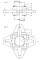
- la figure 3 est une vue en plan et partiellement en coupe du dispositif d'assemblage, selon un autre mode de réalisation ;
- la figure 4 est une vue en élévation d'une bague d'assemblage du dispositif, selon un autre mode de réalisation ;
- la figure 5 est une vue en plan de la bague représentée dans la figure 4 ;
- la figure 6 est une vue de dessus de la bride ou chape d' extrémité d'un élément tubulaire horizontal, conçue pour être engagée sur l'une des branches de la bague représentée dans les figures 4 et 5 ;
- la figure 7 est une vue en bout de la bride représentée dans la figure 6 ;
- la figure 8 est une vue de dessous de cette bride ;
- la figure 9 est une vue en élévation du dispositif d'assemblage, alors que la bride d'un élément tubulaire horizontal est en cours d'engagement sur la branche correspondante de la bague d'un élément tubulaire vertical, la clavette étant représentée partiellement engagée pour faciliter la compréhension.
- Figure 1 is a plan view and partially in section of the assembly device according to the present invention, according to one embodiment;
- Figure 2 is a partial sectional view of the device shown in Figure 1, this section being taken along line AA of this figure;
- Figure 3 is a plan view and partially in section of the assembly device, according to another embodiment;
- Figure 4 is an elevational view of an assembly ring of the device, according to another embodiment;
- Figure 5 is a plan view of the ring shown in Figure 4;
- Figure 6 is a top view of the end flange or yoke of a horizontal tubular member, designed to be engaged on one of the branches of the ring shown in Figures 4 and 5;
- Figure 7 is an end view of the flange shown in Figure 6;
- Figure 8 is a bottom view of this flange;
- Figure 9 is an elevational view of the assembly device, while the flange of a horizontal tubular member is being engaged on the corresponding branch of the ring of a vertical tubular member, the key being shown partially engaged to facilitate understanding.
Comme représenté plus particulièrement dans les figures 1 et 2, le dispositif d'assemblage d'éléments tubulaires conforme à la présente invention est constitué par une bague 1 pourvue de quatre bras radiaux 2, disposés à angle droit l'un par rapport à l'autre, cette bague 1 étant engagée sur un élément tubulaire vertical 3 et chaque bras étant adapté pour s'engager dans une bride 4 (figurée en coupe dans la figure 1), solidaire de l'extrémité d'un élément tubulaire horizontal 5 (représenté en pointillés pour faciliter la compréhension). Cette bride 4 est pourvue de bossages latéraux 6, prévus pour prendre appui sur le corps de la bague 1, ou sur le côté correspondant des bras radiaux 2 (comme représenté dans la figure 1) situés de part et d'autre du bras emmanché dans la bride d'extrémité de l'élément tubulaire horizontal 5 considéré. Cette bride est bloquée en position d'appui au moyen d'une clavette (non représentée) engagée dans les ouvertures 7,8 diamétralement opposées pratiquées dans l'extrémité de l'élément horizontal 5 en arrière de la bride 4, cette clavette traversant entre ces ouvertures 7,8 un trou rectangulaire 9 dont est pourvu chaque bras radial 2.As shown more particularly in FIGS. 1 and 2, the device for assembling tubular elements according to the present invention consists of a
Comme on peut le remarquer dans la figure 2, la bague 1 comporte un alésage évasé à ses deux extrémités 10,11 opposées et adapté pour sa fixation par soudure sur l'élément tubulaire vertical 3, ou pour sa mise en position fixe, bien que pivotante, sur cet élément 3 par l'intermédiaire d'une bague tronconique (non représentée), soudée sur ce dernier et dont l'extrémité supérieure, de plus petit diamètre, peut s'engager dans l'extrémité inférieure 11 évasée de la bague 1.As can be seen in Figure 2, the
Par ailleurs, comme le montre la figure 1, la bride 4 comporte un alésage central 12, adapté pour permettre l'emmanchement partiel de l'extrémité de l'élément tubulaire 5 et la fixation par soudure de la bride sur ce dernier. Cette bride comporte, en outre, du côté opposé à ses bossages 6, c'est-à-dire du côté de l'élément 5, deux encoches 13, diamétralement opposées et correspondant aux ouvertures rectangulaires 7,8 d'emmanchement de clavette et, par là, au trou rectangulaire 9 du bras radial 2. A noter que le fond de ces encoches est adapté pour servir d'appui à la face de la clavette qui repousse la bride 4 vers la bague 1, quand l'autre face opposée de cette clavette est en contact avec le bord extérieur 14 du trou rectangulaire 9.Furthermore, as shown in FIG. 1, the
Dans le mode de réalisation qui vient d'être décrit en relation avec les figures 1 et 2, on peut noter que les bras radiaux, sur lesquels s'appuient les bossages 6 des brides 4 (dont une est représentée en pointillés pour faciliter la compréhension), ne peuvent pas être utilisés pour l'engagement de brides identiques d'autres éléments tubulaires perpendiculaires aux éléments 5 déjà en place. Afin de pallier cet inconvénient, une autre conception de bride 15 est prévue. Cette bride 15, fixée de manière identique à celle des autres brides 4 à l'extrémité d'un élément tubulaire 16, est pourvue de bossages latéraux 17, adaptés pour prendre appui sur le côté des bossages 6 des autres brides 4, et comporte deux saillies avant 18,19 diamétralement opposées, encadrant le dessus et le dessous du bras radial 2 engagé en elle, et pourvues d'ouvertures d'engagement de clavette 20 (représentée en pointillés dans la figure 1) similaires et de même disposition que celles des extrémités des autres éléments 5.In the embodiment which has just been described in relation to FIGS. 1 and 2, it can be noted that the radial arms, on which the
Dans un autre mode de réalisation de la présente invention, représenté dans la figure 3, la bague d'assemblage 1 est pourvue, entre ses bras radiaux 2, de nervures extérieures 21 angulaires, dont les bords servent d'appui aux bossages latéraux 22 des brides portées par des éléments tubulaires 23. A noter que ces brides sont conçues de la même manière que les brides 4 (de la figure 1), si ce n'est que leurs bossages 22 sont moins écartés latéralement et moins proéminents que les bossages 6 de ces brides. Cette disposition d'assemblage permet de monter quatre éléments horizontaux perpendiculaires entre eux sur une même bague, sans que leurs brides identiques se gênent entre elles. On doit remarquer, en outre, que chaque nervure d'appui 21 comporte un trou cylindrique 24, adapté pour l'introduction à force d'une broche conique de fixation d'une chape d'extrémité de barre diagonale ou de triangulation.In another embodiment of the present invention, represented in FIG. 3, the
Dans un autre mode encore de réalisation du dispositif d'assemblage selon l'invention et comme on le voit dans les figures 4 à 9, la bague 31, représentée dans les figures 4 et 5, engagée et fixée sur un élément tubulaire vertical 32, est sous forme d'une étoile à quatre branches 33 dont chacune constitue un bras radial adapté pour recevoir l'engagement d'une bride ou chape 34, représentée dans les figures 6 à 8, l'assemblage étant bloqué, comme on le voit au mieux dans la figure 9, au moyen d'une clavette plate 35. Chaque branche 33 de la bague est pourvue d'un évidement radial 36 en forme de V, débouchant par son évasement sur la paroi extérieure du tube 32. Chaque branche 33 comporte également, de part et d'autre de son évidement 36, des bossages latéraux 37,38, 39, conçus sous forme de gradins et adaptés pour recevoir l'appui des extrémités frontales 40,41 de la bride 34, solidaire de l'élément tubulaire radial 42. Comme représenté au mieux dans la figure 9, ces gradins d'appui sont prévus sur les deux faces supérieure 43 et inférieure 44 de chaque branche 33, sur une épaisseur et une largeur suffisante et déterminée pour assurer une assise importante aux extrémités 40,41 correspondantes de la bride 34 et une stabilité directionnelle à l'élément tubulaire radial 42, aussi bien dans un plan vertical que dans un plan horizontal, lors de l'opération de blocage de la clavette 35,In yet another embodiment of the assembly device according to the invention and as seen in FIGS. 4 to 9, the
A noter que la bague 31, comme on le voit au mieux dans la figure 5, est fixée sur l'élément tubulaire vertical 32 en plusieurs points radiaux fournis par les secteurs intermédiaires 45,46,47,48 aux évidements radiaux 36 des branches 33 de cette bague.Note that the
Par ailleurs, comme on le remarque en particulier dans les figures 4 et 9, les bossages ou gradins d'appui de bride prévus sur chaque branche 33 sont distribués de manière qu'il existe deux gradins 37,38 sur la face supérieure 43 et un seul gradin 39 sur la face inférieure 44 de cette branche, cette disposition étant adoptée pour permettre à l'élément tubulaire radial 42, en cours d'enclenchement, un certain débattement dans le plan vertical et provoquer l'enfoncement pour ainsi dire automatique de la clavette prisonnière 35 dans l'évidement 36 de la branche 33 et sa pénétration en suivant dans l'évidement inférieur de la bride 34.Furthermore, as noted in particular in FIGS. 4 and 9, the bosses or steps of flange support provided on each
En outre, comme représenté dans les figures 6 à 9, chaque bride ou chape 34 est constituée de deux éléments 49,50 en forme de L fixés ensemble par l'arête de leur petite aile 51, l'arête de leur grande aile étant adaptée à la forme du gradin 37,39 correspondant de la branche 33, pour venir en appui ferme et stable sur ces gradins. L'élément inférieur 50 comporte un évidement 52 de pénétration de l'extrémité de pointe de clavette 35, fermé sur ses quatre côtés, alors que l'élément supérieur 49 comporte un évidement 53 débouchant dans la petite aile 51, afin de permettre l'introduction de la clavette 35, dont l'extrémité de pointe est renflée latéralement, et la rendre prisonnière lorsque la bride 34 constituée par ces deux éléments sera fixée en fabrication sur l'extrémité de l'élément tubulaire radial 42. A noter que l'élément supérieur 49 comporte, en outre, une cavité intérieure 54 correspondant à son évidement 52 et ayant une largeur suffisante pour loger le renflement de pointe de la clavette et l'escamoter lors de l'engagement de la bride sur la branche 33 choisie de la bague 31.In addition, as shown in Figures 6 to 9, each flange or
Claims (14)
Priority Applications (1)
| Application Number | Priority Date | Filing Date | Title |
|---|---|---|---|
| AT81401879T ATE18785T1 (en) | 1980-12-04 | 1981-11-27 | DEVICE FOR THE DIRECTIONAL CONNECTION OF PARTICULARLY TUBULAR FRAMEWORK ELEMENTS. |
Applications Claiming Priority (4)
| Application Number | Priority Date | Filing Date | Title |
|---|---|---|---|
| FR8025734 | 1980-12-04 | ||
| FR8025734A FR2495672A1 (en) | 1980-12-04 | 1980-12-04 | Nodal joint ring for tubular scaffolding - has radial arms with slots for tapered keys to secure tubes |
| FR8120117A FR2515238A1 (en) | 1981-10-27 | 1981-10-27 | Nodal joint ring for tubular scaffolding - has radial arms with slots for tapered keys to secure tubes |
| FR8120117 | 1981-10-27 |
Publications (2)
| Publication Number | Publication Date |
|---|---|
| EP0053970A1 true EP0053970A1 (en) | 1982-06-16 |
| EP0053970B1 EP0053970B1 (en) | 1986-03-26 |
Family
ID=26222103
Family Applications (1)
| Application Number | Title | Priority Date | Filing Date |
|---|---|---|---|
| EP81401879A Expired EP0053970B1 (en) | 1980-12-04 | 1981-11-27 | Means for the directional connection of tubular scaffolding elements |
Country Status (8)
| Country | Link |
|---|---|
| US (1) | US4530616A (en) |
| EP (1) | EP0053970B1 (en) |
| BR (1) | BR8107883A (en) |
| CA (1) | CA1204803A (en) |
| DE (1) | DE3174216D1 (en) |
| ES (1) | ES8300370A1 (en) |
| IT (1) | IT1168565B (en) |
| OA (1) | OA06961A (en) |
Cited By (7)
| Publication number | Priority date | Publication date | Assignee | Title |
|---|---|---|---|---|
| FR2553456A1 (en) * | 1983-10-18 | 1985-04-19 | Roux Marcel | Device for directional assembly between horizontal and vertical tubular elements of a scaffold |
| EP0147496A1 (en) * | 1984-01-05 | 1985-07-10 | Gerhard Dobersch | Connection device for counter braces to posts of a modular scaffold |
| GB2151275A (en) * | 1983-12-13 | 1985-07-17 | Ruth Langer | Dismantable lattice-work construction |
| EP0376430A1 (en) * | 1988-12-28 | 1990-07-04 | Tatsuo Ono | Support system |
| GB2257227A (en) * | 1991-07-01 | 1993-01-06 | Sgb Holdings Ltd | Connecting construction for pipes,e.g. scaffolding |
| EP0990748A1 (en) * | 1998-09-29 | 2000-04-05 | plettac AG | Scaffold standard with improved stress bearing capacity |
| CN105863247A (en) * | 2016-05-20 | 2016-08-17 | 江苏业强脚手架科技发展有限公司 | Direct-plug type scaffold with locking block |
Families Citing this family (8)
| Publication number | Priority date | Publication date | Assignee | Title |
|---|---|---|---|---|
| FR2577964B1 (en) * | 1985-02-27 | 1987-03-27 | Cegedur | SCAFFOLDING KNOT OR SIMILAR STRUCTURE AND ASSEMBLY METHOD |
| ES2078833B1 (en) * | 1992-08-06 | 1996-08-16 | Castillo Cabello Eugenio Del | IMPROVEMENTS INTRODUCED IN STAIRS FOR CONSTRUCTION SCAFFOLDS |
| CA2201535C (en) * | 1997-04-02 | 2006-09-19 | Aluma Systems Corp. | Scaffolding connector |
| CA2634573C (en) * | 2008-06-10 | 2011-05-24 | Peter J. Rogers | Modular scaffold system |
| DE102011001796A1 (en) | 2011-04-05 | 2012-10-11 | Wilhelm Layher Verwaltungs-Gmbh | scaffolding post |
| WO2012163340A1 (en) * | 2011-06-01 | 2012-12-06 | Wilhelm Layher Verwaltungs-Gmbh | Arrangement of a scaffolding component and of a vertical scaffolding element |
| GB2502339B (en) | 2012-05-25 | 2018-02-07 | Cosmetic Warriors Ltd | Solid cosmetic composition |
| US9835188B2 (en) * | 2013-03-14 | 2017-12-05 | Titan Formwork Systems Llc | Universal wedge clamp |
Citations (5)
| Publication number | Priority date | Publication date | Assignee | Title |
|---|---|---|---|---|
| GB1278243A (en) * | 1968-09-24 | 1972-06-21 | Alfred Victor Elson | Mounting arrangements for scaffolding |
| FR2247601A1 (en) * | 1973-10-10 | 1975-05-09 | Sgb Group Ltd | |
| GB1408566A (en) * | 1971-09-17 | 1975-10-01 | Evans & Sons Ltd C | Couplings for use in scaffold structures for coupling an upright member to a transom or ledger member |
| FR2288199A1 (en) * | 1974-10-16 | 1976-05-14 | Layher Eberhard | TUBULAR SCAFFOLDING SYSTEM, ESPECIALLY FOR CONSTRUCTION |
| FR2450925A1 (en) * | 1979-03-08 | 1980-10-03 | Evans & Sons Ltd C | IMPROVED CONNECTION FOR SCAFFOLDING |
Family Cites Families (1)
| Publication number | Priority date | Publication date | Assignee | Title |
|---|---|---|---|---|
| NL7701060A (en) * | 1977-02-02 | 1978-08-04 | Ipa Scaffolding Nederland B V | BUILDING SCAFFOLDING AS WELL AS SUPPORTING NOCKS RINGING ELEMENT FOR THE STANDS OF SUCH SCAFFOLDING. |
-
1981
- 1981-11-27 DE DE8181401879T patent/DE3174216D1/en not_active Expired
- 1981-11-27 EP EP81401879A patent/EP0053970B1/en not_active Expired
- 1981-12-04 IT IT84984/81A patent/IT1168565B/en active
- 1981-12-04 OA OA57558A patent/OA06961A/en unknown
- 1981-12-04 ES ES507746A patent/ES8300370A1/en not_active Expired
- 1981-12-04 CA CA000391523A patent/CA1204803A/en not_active Expired
- 1981-12-04 BR BR8107883A patent/BR8107883A/en unknown
-
1984
- 1984-03-02 US US06/585,434 patent/US4530616A/en not_active Expired - Fee Related
Patent Citations (5)
| Publication number | Priority date | Publication date | Assignee | Title |
|---|---|---|---|---|
| GB1278243A (en) * | 1968-09-24 | 1972-06-21 | Alfred Victor Elson | Mounting arrangements for scaffolding |
| GB1408566A (en) * | 1971-09-17 | 1975-10-01 | Evans & Sons Ltd C | Couplings for use in scaffold structures for coupling an upright member to a transom or ledger member |
| FR2247601A1 (en) * | 1973-10-10 | 1975-05-09 | Sgb Group Ltd | |
| FR2288199A1 (en) * | 1974-10-16 | 1976-05-14 | Layher Eberhard | TUBULAR SCAFFOLDING SYSTEM, ESPECIALLY FOR CONSTRUCTION |
| FR2450925A1 (en) * | 1979-03-08 | 1980-10-03 | Evans & Sons Ltd C | IMPROVED CONNECTION FOR SCAFFOLDING |
Cited By (9)
| Publication number | Priority date | Publication date | Assignee | Title |
|---|---|---|---|---|
| FR2553456A1 (en) * | 1983-10-18 | 1985-04-19 | Roux Marcel | Device for directional assembly between horizontal and vertical tubular elements of a scaffold |
| GB2151275A (en) * | 1983-12-13 | 1985-07-17 | Ruth Langer | Dismantable lattice-work construction |
| EP0147496A1 (en) * | 1984-01-05 | 1985-07-10 | Gerhard Dobersch | Connection device for counter braces to posts of a modular scaffold |
| EP0376430A1 (en) * | 1988-12-28 | 1990-07-04 | Tatsuo Ono | Support system |
| GR890100856A (en) * | 1988-12-28 | 1991-03-15 | Tatsuo Ono | Process for the junction of support brackets and support system |
| GB2257227A (en) * | 1991-07-01 | 1993-01-06 | Sgb Holdings Ltd | Connecting construction for pipes,e.g. scaffolding |
| GB2257227B (en) * | 1991-07-01 | 1994-08-17 | Sgb Holdings Ltd | Connecting construction for pipes,e.g.scaffolding |
| EP0990748A1 (en) * | 1998-09-29 | 2000-04-05 | plettac AG | Scaffold standard with improved stress bearing capacity |
| CN105863247A (en) * | 2016-05-20 | 2016-08-17 | 江苏业强脚手架科技发展有限公司 | Direct-plug type scaffold with locking block |
Also Published As
| Publication number | Publication date |
|---|---|
| BR8107883A (en) | 1982-09-08 |
| EP0053970B1 (en) | 1986-03-26 |
| ES507746A0 (en) | 1982-11-01 |
| IT8184984A0 (en) | 1981-12-04 |
| DE3174216D1 (en) | 1986-04-30 |
| US4530616A (en) | 1985-07-23 |
| IT1168565B (en) | 1987-05-20 |
| OA06961A (en) | 1983-07-31 |
| ES8300370A1 (en) | 1982-11-01 |
| CA1204803A (en) | 1986-05-20 |
Similar Documents
| Publication | Publication Date | Title |
|---|---|---|
| EP0053970B1 (en) | Means for the directional connection of tubular scaffolding elements | |
| EP0236185B1 (en) | Apparatus for fastening a head rest to a vehicle seat | |
| CH635160A5 (en) | CONNECTION FOR BUILDING SCAFFOLDS. | |
| EP0530114A1 (en) | Dismountable assembly device for metallic framework elements | |
| EP0974546A1 (en) | Assembly device for metallic lattice members | |
| FR2513290A1 (en) | TUBULAR TYPE SCAFFOLDS, METHOD OF MOUNTING AND HORIZONTAL CROSSINGS OF THESE SCAFFOLDS | |
| EP0098784B1 (en) | Resilient mounting system for two elements | |
| EP2767499B1 (en) | Splinting device for connecting two strut members and assembly comprising two strut members and such splinting devices | |
| FR2621342A1 (en) | SCREW WITH TRIANGULAR ELEMENTS | |
| FR2467940A1 (en) | FITTING FOR JOINING MATTS AND CROSSERS OF A SCAFFOLDING OR THE LIKE | |
| EP0527086A1 (en) | Arrangement for connecting or assembling the end of a cross member to an upright an seaffolding system including these cross members provided with such arrangement on both ends | |
| EP0008555A1 (en) | Assembly device for producing frame-works and light metallic structures | |
| EP0500459B1 (en) | Three-dimensional tubular structure | |
| FR2495672A1 (en) | Nodal joint ring for tubular scaffolding - has radial arms with slots for tapered keys to secure tubes | |
| FR2461841A1 (en) | Pinned connection shelf bracket to box section post - has D-section pin in tapered D-shape bracket flange window and in inclined post slot hole | |
| FR2515238A1 (en) | Nodal joint ring for tubular scaffolding - has radial arms with slots for tapered keys to secure tubes | |
| FR2496741A3 (en) | Connector for tubular scaffolding - uses annular link collars surrounding vertical tubes to receive ends of horizontal tubes | |
| FR2571793A1 (en) | TUBE COUPLING DEVICE, PARTICULARLY SUITABLE FOR THE INSTALLATION OF PILES FOR SEA DRILLING PLATFORMS | |
| EP4026961B1 (en) | Assembly method between an aluminium end of a tubular post of a supporting tower and a steel protective ring | |
| FR3068091A1 (en) | HOLDING SYSTEM HAVING DECAL APPENDICES ANGULARLY | |
| EP0797715B1 (en) | Deformable structure | |
| EP1260462A1 (en) | Supporting frame for belt conveyor and belt conveyor comprising same | |
| FR2833028A1 (en) | INTERLOCKING ASSEMBLY FOR SCAFFOLDING | |
| FR2547845A1 (en) | Multidirectional traffic barrier | |
| FR2483994A3 (en) | Post to rail scaffolding coupling - allows angling of rail in plan and elevation using hollow rail end return secured in post cup by tapered pin |
Legal Events
| Date | Code | Title | Description |
|---|---|---|---|
| PUAI | Public reference made under article 153(3) epc to a published international application that has entered the european phase |
Free format text: ORIGINAL CODE: 0009012 |
|
| AK | Designated contracting states |
Designated state(s): AT DE GB NL SE |
|
| TCAT | At: translation of patent claims filed | ||
| TCNL | Nl: translation of patent claims filed | ||
| 17P | Request for examination filed |
Effective date: 19820805 |
|
| DET | De: translation of patent claims | ||
| GRAA | (expected) grant |
Free format text: ORIGINAL CODE: 0009210 |
|
| AK | Designated contracting states |
Kind code of ref document: B1 Designated state(s): AT DE GB NL SE |
|
| PG25 | Lapsed in a contracting state [announced via postgrant information from national office to epo] |
Ref country code: NL Effective date: 19860326 Ref country code: AT Effective date: 19860326 |
|
| REF | Corresponds to: |
Ref document number: 18785 Country of ref document: AT Date of ref document: 19860415 Kind code of ref document: T |
|
| PG25 | Lapsed in a contracting state [announced via postgrant information from national office to epo] |
Ref country code: SE Effective date: 19860331 |
|
| REF | Corresponds to: |
Ref document number: 3174216 Country of ref document: DE Date of ref document: 19860430 |
|
| NLV1 | Nl: lapsed or annulled due to failure to fulfill the requirements of art. 29p and 29m of the patents act | ||
| PLBE | No opposition filed within time limit |
Free format text: ORIGINAL CODE: 0009261 |
|
| STAA | Information on the status of an ep patent application or granted ep patent |
Free format text: STATUS: NO OPPOSITION FILED WITHIN TIME LIMIT |
|
| 26N | No opposition filed | ||
| PGFP | Annual fee paid to national office [announced via postgrant information from national office to epo] |
Ref country code: GB Payment date: 19891031 Year of fee payment: 9 |
|
| PGFP | Annual fee paid to national office [announced via postgrant information from national office to epo] |
Ref country code: DE Payment date: 19891111 Year of fee payment: 9 |
|
| PG25 | Lapsed in a contracting state [announced via postgrant information from national office to epo] |
Ref country code: GB Effective date: 19901127 |
|
| GBPC | Gb: european patent ceased through non-payment of renewal fee | ||
| PG25 | Lapsed in a contracting state [announced via postgrant information from national office to epo] |
Ref country code: DE Effective date: 19910801 |