EP0053728B1 - Apparatus for detecting defects of printing sheets - Google Patents
Apparatus for detecting defects of printing sheets Download PDFInfo
- Publication number
- EP0053728B1 EP0053728B1 EP81109448A EP81109448A EP0053728B1 EP 0053728 B1 EP0053728 B1 EP 0053728B1 EP 81109448 A EP81109448 A EP 81109448A EP 81109448 A EP81109448 A EP 81109448A EP 0053728 B1 EP0053728 B1 EP 0053728B1
- Authority
- EP
- European Patent Office
- Prior art keywords
- sheet
- detector
- printing
- printing sheet
- detection timing
- Prior art date
- Legal status (The legal status is an assumption and is not a legal conclusion. Google has not performed a legal analysis and makes no representation as to the accuracy of the status listed.)
- Expired
Links
Images
Classifications
-
- B—PERFORMING OPERATIONS; TRANSPORTING
- B65—CONVEYING; PACKING; STORING; HANDLING THIN OR FILAMENTARY MATERIAL
- B65H—HANDLING THIN OR FILAMENTARY MATERIAL, e.g. SHEETS, WEBS, CABLES
- B65H7/00—Controlling article feeding, separating, pile-advancing, or associated apparatus, to take account of incorrect feeding, absence of articles, or presence of faulty articles
- B65H7/02—Controlling article feeding, separating, pile-advancing, or associated apparatus, to take account of incorrect feeding, absence of articles, or presence of faulty articles by feelers or detectors
- B65H7/14—Controlling article feeding, separating, pile-advancing, or associated apparatus, to take account of incorrect feeding, absence of articles, or presence of faulty articles by feelers or detectors by photoelectric feelers or detectors
-
- B—PERFORMING OPERATIONS; TRANSPORTING
- B41—PRINTING; LINING MACHINES; TYPEWRITERS; STAMPS
- B41F—PRINTING MACHINES OR PRESSES
- B41F33/00—Indicating, counting, warning, control or safety devices
- B41F33/04—Tripping devices or stop-motions
- B41F33/14—Automatic control of tripping devices by feelers, photoelectric devices, pneumatic devices, or other detectors
-
- B—PERFORMING OPERATIONS; TRANSPORTING
- B65—CONVEYING; PACKING; STORING; HANDLING THIN OR FILAMENTARY MATERIAL
- B65H—HANDLING THIN OR FILAMENTARY MATERIAL, e.g. SHEETS, WEBS, CABLES
- B65H7/00—Controlling article feeding, separating, pile-advancing, or associated apparatus, to take account of incorrect feeding, absence of articles, or presence of faulty articles
- B65H7/02—Controlling article feeding, separating, pile-advancing, or associated apparatus, to take account of incorrect feeding, absence of articles, or presence of faulty articles by feelers or detectors
-
- B—PERFORMING OPERATIONS; TRANSPORTING
- B65—CONVEYING; PACKING; STORING; HANDLING THIN OR FILAMENTARY MATERIAL
- B65H—HANDLING THIN OR FILAMENTARY MATERIAL, e.g. SHEETS, WEBS, CABLES
- B65H7/00—Controlling article feeding, separating, pile-advancing, or associated apparatus, to take account of incorrect feeding, absence of articles, or presence of faulty articles
- B65H7/02—Controlling article feeding, separating, pile-advancing, or associated apparatus, to take account of incorrect feeding, absence of articles, or presence of faulty articles by feelers or detectors
- B65H7/06—Controlling article feeding, separating, pile-advancing, or associated apparatus, to take account of incorrect feeding, absence of articles, or presence of faulty articles by feelers or detectors responsive to presence of faulty articles or incorrect separation or feed
Definitions
- This invention relates to an apparatus for detecting defects at a side edge of printing sheet comprising a) a detector for detecting presence or absence of said printing sheet; b) a detection timing means for producing a detection timing signal and c) means for producing an output signal.
- a printing sheet 2 fed from a sheet feeder 1 is stopped by a front lay 3, and the position of the sheet is determined by the front lay and side lay, not shown, by being urged against the side lay 4.
- the sheet 2 is gripped by grippers of a swinger 5 to be transferred to an impression cylinder 6, and then printed with a first color by a blanket cylinder 8 which is supplied with the printing ink from a plate cylinder 7.
- the printed sheet is transferred to a second printing unit comprising identical rollers through an intermediate cylinder 9 to be printed with a second color.
- the printed sheet is transferred to a receiving cylinder 11 via a transfer cylinder 10 and then conveyed to a delivery device 13 by being gripped by grippers of a conveyor chain 12.
- a printing sheet 2 collides against front lays 3 to have its front edge corrected and is laterally urged against a side lay 4, not shown in Fig. 2, to correct its lateral position.
- a photoelectric detector located a little ahead of the front lays 3.
- the photoelectric detector comprises two light emitting elements 14 located beneath the sheet 2 near its opposite sides and two light receiving elements 15 disposed to oppose the light emitting elements 14.
- the feeding operation of the sheet feeder 1 is stopped while at the same time printing operation of a printing cylinder is prevented by displacing the same to an inoperative position, thus preventing improper printing.
- Such photoelectric detectors can also detect a state in which one or both front corners of the sheet are bent or folded back.
- the photoelectric detectors are generally located at positions substantially remote from both side edges of the sheet, they can not detect a state in which small front corners are bent or folded back.
- the bent or folded back states at the corners are liable to be formed when sheets are stacked into another stack or when automatic device for counting the number of sheets is used. Especially, as the sheet number counter sequentially turns up the corners of stacked sheets with a mechanical device, the chance of bending up the corners increases. Such corner bending up also occurs at the corners of the rear edge of the sheet. Further, the sheet often breaks or is formed with notches at intermediate points along side edges thereof.
- Figs., 3a, 3b and 3c show abnormal states along its side edge.
- arrows show the direction of movement of the sheet.
- Fig. 3a shows a small bent up or folded back portion at the front end of one side
- Fig. 3b shows a small bent up or folded back portion at the rear end of the same side
- Fig. 3c shows a small notch at an intermediate point of the same side.
- DE-A-2850 351 teaches a detector for detecting presence or absence of a printing sheet, having a detection timing means for producing a detection timing signal and means for producing an output signal.
- the known apparatus is used for counting the paper sheets passing into the printing press and also those passing out of it and derives an output signal from the difference between the two counting results, if said difference exceeds the predetermined value, which is the case if there is an accumulation of paper in the press.
- the detector provided in this known apparatus is only able to supply a counting signal, if a sheet passes by it.
- the detection timing means provided in this known apparatus ensure that the detector is switched on after the front edge of the sheet has passed by it and the detector is switched off, before the rear edge of the sheet has passed by it.
- the detector in the known apparatus is only suitable for supplying a counting signal when a sheet is present, so that an output signal can be produced when the counting result for the intake- side detector differs by more than a predetermined value from the counting result of the outlet-side detector.
- the known apparatus is not suitable for determining defects on the side edge of a printing sheet.
- the problem of the invention is to provide a simply constructed apparatus for determining defects on the side edge of travelling printing sheets.
- the detection apparatus shown in Fig. 4 comprises a detection sensor 20 positioned at the front end and at the lefthand side of the sheet 2 which is moved in the direction of an arrow.
- the sensor 20 is positioned a little above the sheet 2.
- the detection sensor 20 comprises a light projector which projects light downwardly and a light receiver which receives light reflected by the- surface of the sheet 2 and produces its output signal via a lead wire 21, the output signal being produced when the light receiver does not receive any light meaning that the front corner of the sheet is bent up.
- the sensor 20 is secured to one end of a supporting lever 22 secured by a screw 25 to the upper surface of a supporting block 24 slidably mounted on a rod 23.
- the rod 23 is provided transversely above the path of the paper sheet 2.
- the supporting block 24 is secured to the rod 23 by the screw 26 thus positioning the detection sensor 20.
- the sensor 20 is positioned so that it detects a corner bend larger than 18 mm.
- an identical detection sensor is mounted on the rod 23 to confront the opposite front corner of the sheet.
- the timing signal generator comprises a sector shaped detecting member 28 secured to a shaft 29 which is rotated in synchronism with a driving mechanism of a swinger so that the shaft 29 is rotated one revolution when the swinger makes one reciprocation, that is each sheet is printed.
- a similar sector shaped detecting member 30 is also rotatably mounted on the rotary shaft 29 to be able to overlap the detecting member 30 over any desired angle.
- the overlap angle of the two sector shaped members 28 and 30, that is the angle of the overlapped assembly can be adjusted by an arcuate slot 31a of the sector 30 and a fastening bolt 31 secured to the sector 28.
- the timing sensor 32 produces a timing signal while it faces the peripheries 28a and 30a and the generated timing signal is outputted through a lead wire 33.
- the relative position of the timing sensor 32 and the detecting members 28 and 30 is selected such that the timing signal is generated between an instant at which the front end of the sheet 2 passes by the detection sensor 20 as shown in Fig. 4 and an instant at which the rear end of the sheet 2 passes by the detection sensor 20.
- the front edge of the periphery 28a faces the timing sensor 32
- the rear edge of the periphery 30a faces the timing sensor 32
- a detection sensor 35 disposed at the right front corner of the sheet and comprising a light projector 35a and a light receiver 35b, and an initiation sensor 36 which is started to operate when a first sheet comes to engage a front register and thereafter continues to output an initiation signal until the printing operation is stopped. Accordingly, as soon as the printing operation is commenced, the initiation sensor 36 produces an initiation signal and when the sheet 2 passes by the detection sensors 20 and 35 the timing sensor 32 produces timing signals. In response to the initiation signal and the timing signals, an AND gate circuit 37 is enabled.
- the detection sensor 20 or 35 When there is a folded or bent portion or a notch on the left or right side edge of the sheet, the detection sensor 20 or 35 produces a detection signal which is applied to an amplifier 39 via an OR gate circuit 38 and the waveform of the output of the amplifier 39 is shaped by a waveform shaper 40, the output thereof being amplified by an amplifier 41 and then applied to an output device 42 via the AND gate circuit 37.
- the output device 42 When supplied with the detection signal, the output device 42 self-holds its operative state and as the operation of the sheet feeder 1 is stopped it renders inoperative or throws off various cylinders and rollers of the printing press to terminate the printing operation. Concurrently therewith an alarming device is operated to inform that the sheet is defective.
- Fig. 7 is a timing chart showing various signals of the control circuit, in which curve (a) shows the initiation signal, (b) the detection timing signal, (c), (d) and (e) the detection signal, the output signal of the AND gate circuit 37 and the output signal of the output device 42 respectively, which are produced when a bent up or folded portion presents at the fore end of the sheet.
- Curves (f), (g) and (h) show the detection signal, the output signal of the AND gate circuit 37, and the output signal of the output device 42, respectively when bent or folded portion is present at the rear end of the sheet, whereas curves (i), (j) and (k) represent the detection signal, the output signal of the AND gate circuit 37, and the output signal of the output device 42 when there is a defect, for example a notch, at an intermediate point along one side edge of the sheet.
- a reflected light detector was used as the detection sensor, it will be clear that a light detector that detects light transmitting through the sheet can also be used. Further, static capacitance type or ultra sonic type detection sensor may also be used.
- Fig. 8 shows the electric circuit of another embodiment of this invention in which a sheet 2 fed onto a metal feed plate 44 is correctly positioned by a front lay 3 and a side lay 4 (see Fig. 1).
- the tips of metal rods 45 are made to contact the left and right sides of the front end of the sheet 2. Accordingly, when there is a bent or folded portion or a notch at either one of the front corners of the sheet 2, the metal rod 45 will come into electrical contact with the metal feed plate 44.
- the metal rods 45 and the feed plate 44 constitute a detection sensor.
- an initiation switch 46 which is closed concurrently with the engagement of the first sheet against the front lay 3 and held in the closed state during the printing operation
- a timing switch 47 which comprises adjustable sector shaped detection members as shown in Fig. 5 and is held closed while the sector shaped detection members 28 and 30 pass by the detection sensor 45.
- a series circuit including the feed plate 44, metal rods 45, the initiation switch 46, and the timing switch 47 is closed across detection terminals D1 and D2.
- a source of supply 48 and a relay 49 are connected in series across the output side of the terminals D1 and D2.
- Fig. 9 shows another embodiment of this invention in which the voltage of an AC source is stepped down by a transformer 51 and then converted into a constant DC voltage by a rectifier 52.
- a circuit between detection terminals D1 and D2 is closed like the embodiment shown in Fig. 8 a voltage is established after a predetermined time determined by a time constant circuit made up of a capacitor C and a resistor R to apply a positive voltage to the base electrode of a transistor 53, thus turning on the same. Consequently, a transistor 54 is also turned on to energize a relay 55 for closing its contact 56 whereby a driving output appears on the output terminals 01 and 02.
- the detection sensors were provided on both sides of the front edge of the sheet, where a bent or folded portion or a notch occurs only along one side edge of the sheet, the detection sensor may be provided only on the left or right side of the sheet.
- the apparatus for detecting the defects of a printing sheet according to this invention can efficiently detect such small defects as a bent or folded portion and a notch at the side edge of the printing sheet, so it is possible to prevent beforehand formation of defective printed matter caused by such defects of the printing sheet. Further, as it is possible to prevent a defective printing sheet from entering into the printing press, defective printing of succeeding sheets can be effectively prevented. This also prevents wrapping up a defective sheet about a blanket cylinder, as well as damage of a blanket and printing press.
Landscapes
- Inking, Control Or Cleaning Of Printing Machines (AREA)
- Controlling Sheets Or Webs (AREA)
- Storage Of Web-Like Or Filamentary Materials (AREA)
- Investigating Materials By The Use Of Optical Means Adapted For Particular Applications (AREA)
Abstract
Description
- This invention relates to an apparatus for detecting defects at a side edge of printing sheet comprising a) a detector for detecting presence or absence of said printing sheet; b) a detection timing means for producing a detection timing signal and c) means for producing an output signal.
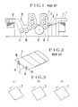
- Referring to Fig. 1 which shows a prior art sheet printing press, a
printing sheet 2 fed from a sheet feeder 1 is stopped by afront lay 3, and the position of the sheet is determined by the front lay and side lay, not shown, by being urged against the side lay 4. Then thesheet 2 is gripped by grippers of aswinger 5 to be transferred to animpression cylinder 6, and then printed with a first color by ablanket cylinder 8 which is supplied with the printing ink from aplate cylinder 7. Then the printed sheet is transferred to a second printing unit comprising identical rollers through anintermediate cylinder 9 to be printed with a second color. After printed with a plurality of colors, the printed sheet is transferred to a receivingcylinder 11 via atransfer cylinder 10 and then conveyed to adelivery device 13 by being gripped by grippers of aconveyor chain 12. - As shown in Fig. 2, a
printing sheet 2 collides againstfront lays 3 to have its front edge corrected and is laterally urged against a side lay 4, not shown in Fig. 2, to correct its lateral position. Usually, an incorrectly fed sheet is detected by a photoelectric detector, located a little ahead of thefront lays 3. The photoelectric detector comprises twolight emitting elements 14 located beneath thesheet 2 near its opposite sides and two light receivingelements 15 disposed to oppose thelight emitting elements 14. With this arrangement, since the light emitted by thelight emitting elements 14 reaches thelight receiving elements 15 by passing through thesheet 2, when two superposed sheets are delivered simultaneously such improper sheet feeding is detected from the fact that the quantity of light transmitted is reduced. When the front edge of thesheet 2 does not reach thefront lays 3, the light would be directly received by thelight receiving elements 15 thus enabling to detect an improperly supplied sheet. Upon detection of such an improperly fed sheet, the feeding operation of the sheet feeder 1 is stopped while at the same time printing operation of a printing cylinder is prevented by displacing the same to an inoperative position, thus preventing improper printing. - Such photoelectric detectors can also detect a state in which one or both front corners of the sheet are bent or folded back. However, since the photoelectric detectors are generally located at positions substantially remote from both side edges of the sheet, they can not detect a state in which small front corners are bent or folded back. Even when three or more detectors are provided for a printing press, since the detectors are located apart from the side edges of the sheet, it is also impossible to detect small bent or folded back states at the corner.
- The bent or folded back states at the corners are liable to be formed when sheets are stacked into another stack or when automatic device for counting the number of sheets is used. Especially, as the sheet number counter sequentially turns up the corners of stacked sheets with a mechanical device, the chance of bending up the corners increases. Such corner bending up also occurs at the corners of the rear edge of the sheet. Further, the sheet often breaks or is formed with notches at intermediate points along side edges thereof.
- Figs., 3a, 3b and 3c show abnormal states along its side edge. In these Figures, arrows show the direction of movement of the sheet. Fig. 3a shows a small bent up or folded back portion at the front end of one side, Fig. 3b shows a small bent up or folded back portion at the rear end of the same side, and Fig. 3c shows a small notch at an intermediate point of the same side.
- Since these abnormal states can not be detected by the prior art photoelectric detectors of the type described above, such defective sheets would be printed thus forming defective printed sheets. Consequently it is necessary to examine printed sheets with eyes so as to check whether they contain defective printed sheets or not. This is not only troublesome but also defective printed sheets must be discarded. In an offset printing press the folded back portion applies a local excessive pressure to the blanket so that such local excessive pressure results in non-uniform printings for all succeeding sheets unless the blanket is substituted by a new one.
- DE-A-2850 351 teaches a detector for detecting presence or absence of a printing sheet, having a detection timing means for producing a detection timing signal and means for producing an output signal.
- The known apparatus is used for counting the paper sheets passing into the printing press and also those passing out of it and derives an output signal from the difference between the two counting results, if said difference exceeds the predetermined value, which is the case if there is an accumulation of paper in the press. Thus, the detector provided in this known apparatus is only able to supply a counting signal, if a sheet passes by it. The detection timing means provided in this known apparatus ensure that the detector is switched on after the front edge of the sheet has passed by it and the detector is switched off, before the rear edge of the sheet has passed by it. Thus, the detector in the known apparatus is only suitable for supplying a counting signal when a sheet is present, so that an output signal can be produced when the counting result for the intake- side detector differs by more than a predetermined value from the counting result of the outlet-side detector. The known apparatus is not suitable for determining defects on the side edge of a printing sheet.
- Thus, the problem of the invention is to provide a simply constructed apparatus for determining defects on the side edge of travelling printing sheets.
- This problem is solved by the combination of the measures of the characterizing part of the new claim 1, namely by the fact that
- said detector is provided at one side of a front edge of a correctly fed printing sheet,
- said detection timing means is arranged to produce said detection timing signal starting at an instant at which the front end of a normal correctly fed printing sheet passes by said detector and ending at an instant at which the rear end of a normal correctly fed printing sheet passes by said detector and
- said means for producing said output signal is arranged to produce that output signal when said detector detects absence of said printing sheets while said detection timing signal is being produced.
- In the accompanying drawings:
- Fig. 1 is a diagrammatic side view of a prior art sheet printing press;
- Fig. 2 is a perspective view showing prior art photoelectric detectors when a sheet of printing paper is correctly positioned by front and side lays;
- Figs. 3a, 3b and 3c are perspective views showing various types of defective states of the sheet;
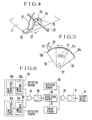
- Fig. 4 is a perspective view showing one embodiment of the apparatus for detecting defects along a side edge of a printing sheet embodying the invention;
- Fig. 5 is a front view showing a timing signal generator;
- Fig. 6 is a block diagram showing the control circuit;
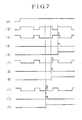
- Fig. 7 is a timing chart showing various signals of the circuit shown in Fig. 6;
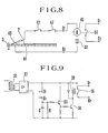
- Fig. 8 is a connection diagram showing another embodiment according to this invention; and
- Fig. 9 is a connection diagram showing still another embodiment of this invention.
- In Fig. 4, it is assumed that a
printing sheet 2 has been positioned at a correct position by a front lay and a side lay shown in Fig. 1. The detection apparatus shown in Fig. 4 comprises adetection sensor 20 positioned at the front end and at the lefthand side of thesheet 2 which is moved in the direction of an arrow. Thesensor 20 is positioned a little above thesheet 2. Thedetection sensor 20 comprises a light projector which projects light downwardly and a light receiver which receives light reflected by the- surface of thesheet 2 and produces its output signal via alead wire 21, the output signal being produced when the light receiver does not receive any light meaning that the front corner of the sheet is bent up. Thesensor 20 is secured to one end of a supportinglever 22 secured by ascrew 25 to the upper surface of a supportingblock 24 slidably mounted on arod 23. Therod 23 is provided transversely above the path of thepaper sheet 2. After adjusting the lateral position and the height of thedetection sensor 20, the supportingblock 24 is secured to therod 23 by thescrew 26 thus positioning thedetection sensor 20. Usually, when about 20 mm of a corner of thesheet 2 is bent the bent portion enters into the printing area, thus resulting in a defective printed matter. For this reason, according to this invention, thesensor 20 is positioned so that it detects a corner bend larger than 18 mm. Although not shown, an identical detection sensor is mounted on therod 23 to confront the opposite front corner of the sheet. - As shown in Fig. 5, the timing signal generator comprises a sector shaped detecting
member 28 secured to ashaft 29 which is rotated in synchronism with a driving mechanism of a swinger so that theshaft 29 is rotated one revolution when the swinger makes one reciprocation, that is each sheet is printed. A similar sector shaped detectingmember 30 is also rotatably mounted on therotary shaft 29 to be able to overlap the detectingmember 30 over any desired angle. The overlap angle of the two sector shapedmembers arcuate slot 31a of thesector 30 and afastening bolt 31 secured to thesector 28. Atiming sensor 32 in the form of a proximity switch, for example, is provided to confront theperipheries members members timing sensor 32 produces a timing signal while it faces theperipheries lead wire 33. The relative position of thetiming sensor 32 and the detectingmembers sheet 2 passes by thedetection sensor 20 as shown in Fig. 4 and an instant at which the rear end of thesheet 2 passes by thedetection sensor 20. More particularly, when the front end of thesheet 2 confronts thedetection sensor 20 the front edge of theperiphery 28a faces thetiming sensor 32, while when the rear end of thesheet 2 faces thedetection sensor 20, the rear edge of theperiphery 30a faces thetiming sensor 32. - The operation of various signals will now be described. In the block diagram shown in Fig. 6, there are provided a detection sensor 35 disposed at the right front corner of the sheet and comprising a
light projector 35a and alight receiver 35b, and aninitiation sensor 36 which is started to operate when a first sheet comes to engage a front register and thereafter continues to output an initiation signal until the printing operation is stopped. Accordingly, as soon as the printing operation is commenced, theinitiation sensor 36 produces an initiation signal and when thesheet 2 passes by thedetection sensors 20 and 35 thetiming sensor 32 produces timing signals. In response to the initiation signal and the timing signals, an ANDgate circuit 37 is enabled. When there is a folded or bent portion or a notch on the left or right side edge of the sheet, thedetection sensor 20 or 35 produces a detection signal which is applied to anamplifier 39 via anOR gate circuit 38 and the waveform of the output of theamplifier 39 is shaped by awaveform shaper 40, the output thereof being amplified by anamplifier 41 and then applied to anoutput device 42 via the ANDgate circuit 37. When supplied with the detection signal, theoutput device 42 self-holds its operative state and as the operation of the sheet feeder 1 is stopped it renders inoperative or throws off various cylinders and rollers of the printing press to terminate the printing operation. Concurrently therewith an alarming device is operated to inform that the sheet is defective. - Fig. 7 is a timing chart showing various signals of the control circuit, in which curve (a) shows the initiation signal, (b) the detection timing signal, (c), (d) and (e) the detection signal, the output signal of the AND
gate circuit 37 and the output signal of theoutput device 42 respectively, which are produced when a bent up or folded portion presents at the fore end of the sheet. Curves (f), (g) and (h) show the detection signal, the output signal of the ANDgate circuit 37, and the output signal of theoutput device 42, respectively when bent or folded portion is present at the rear end of the sheet, whereas curves (i), (j) and (k) represent the detection signal, the output signal of the ANDgate circuit 37, and the output signal of theoutput device 42 when there is a defect, for example a notch, at an intermediate point along one side edge of the sheet. - When there is a bent or folded portion at the front end of the third sheet, as shown by curve (c), a detection signal of this defect is produced an output at time t1 so that the AND
gate circuit 37 immediately produces to operate theoutput device 42. In the same manner, when there is a bent or folded portion at the rear end of the second sheet, a detection signal of this defect is produced at time t2 as shown by curve (f), and where a notch is present at an intermediate point of one side edge of the second sheet a detection signal is produced at time t3 as shown by curve (i). In each case, the ANDgate circuit 37 immediately produces an output to operate theoutput device 42. - Although in the foregoing embodiment a reflected light detector was used as the detection sensor, it will be clear that a light detector that detects light transmitting through the sheet can also be used. Further, static capacitance type or ultra sonic type detection sensor may also be used.
- Fig. 8 shows the electric circuit of another embodiment of this invention in which a
sheet 2 fed onto ametal feed plate 44 is correctly positioned by afront lay 3 and a side lay 4 (see Fig. 1). When thesheet 2 is held in the correct position, the tips ofmetal rods 45 are made to contact the left and right sides of the front end of thesheet 2. Accordingly, when there is a bent or folded portion or a notch at either one of the front corners of thesheet 2, themetal rod 45 will come into electrical contact with themetal feed plate 44. Thus, themetal rods 45 and thefeed plate 44 constitute a detection sensor. There are also provided aninitiation switch 46 which is closed concurrently with the engagement of the first sheet against thefront lay 3 and held in the closed state during the printing operation, and atiming switch 47 which comprises adjustable sector shaped detection members as shown in Fig. 5 and is held closed while the sector shapeddetection members detection sensor 45. A series circuit including thefeed plate 44,metal rods 45, theinitiation switch 46, and thetiming switch 47 is closed across detection terminals D1 and D2. A source ofsupply 48 and arelay 49 are connected in series across the output side of the terminals D1 and D2. When a bent or folded portion at the corner or a notch along the side edge of the sheet is detected when it passes by the metal rods, bothswitches relay 49 is energized to close itscontact 50 with the result that an operation output signal appears acrossoutput terminals - Fig. 9 shows another embodiment of this invention in which the voltage of an AC source is stepped down by a
transformer 51 and then converted into a constant DC voltage by arectifier 52. When a circuit between detection terminals D1 and D2 is closed like the embodiment shown in Fig. 8 a voltage is established after a predetermined time determined by a time constant circuit made up of a capacitor C and a resistor R to apply a positive voltage to the base electrode of atransistor 53, thus turning on the same. Consequently, atransistor 54 is also turned on to energize arelay 55 for closing itscontact 56 whereby a driving output appears on theoutput terminals - Although in the foregoing embodiments the detection sensors were provided on both sides of the front edge of the sheet, where a bent or folded portion or a notch occurs only along one side edge of the sheet, the detection sensor may be provided only on the left or right side of the sheet.
- As above described, the apparatus for detecting the defects of a printing sheet according to this invention can efficiently detect such small defects as a bent or folded portion and a notch at the side edge of the printing sheet, so it is possible to prevent beforehand formation of defective printed matter caused by such defects of the printing sheet. Further, as it is possible to prevent a defective printing sheet from entering into the printing press, defective printing of succeeding sheets can be effectively prevented. This also prevents wrapping up a defective sheet about a blanket cylinder, as well as damage of a blanket and printing press.
Claims (6)
characterized in that
Priority Applications (1)
| Application Number | Priority Date | Filing Date | Title |
|---|---|---|---|
| AT81109448T ATE18379T1 (en) | 1980-12-05 | 1981-10-31 | FACILITIES TO INDICATE ERRORS ON PRINT SHEETS. |
Applications Claiming Priority (2)
| Application Number | Priority Date | Filing Date | Title |
|---|---|---|---|
| JP55172212A JPS5851827B2 (en) | 1980-12-05 | 1980-12-05 | Printing paper side edge detection device |
| JP172212/80 | 1980-12-05 |
Publications (2)
| Publication Number | Publication Date |
|---|---|
| EP0053728A1 EP0053728A1 (en) | 1982-06-16 |
| EP0053728B1 true EP0053728B1 (en) | 1986-03-05 |
Family
ID=15937665
Family Applications (1)
| Application Number | Title | Priority Date | Filing Date |
|---|---|---|---|
| EP81109448A Expired EP0053728B1 (en) | 1980-12-05 | 1981-10-31 | Apparatus for detecting defects of printing sheets |
Country Status (5)
| Country | Link |
|---|---|
| US (1) | US4480546A (en) |
| EP (1) | EP0053728B1 (en) |
| JP (1) | JPS5851827B2 (en) |
| AT (1) | ATE18379T1 (en) |
| DE (1) | DE3174002D1 (en) |
Families Citing this family (11)
| Publication number | Priority date | Publication date | Assignee | Title |
|---|---|---|---|---|
| ES8402225A1 (en) * | 1982-05-29 | 1984-01-16 | Heidelberger Druckmasch Ag | Device for controlling sheets fed to the feed table of a printing press. |
| JPS63312840A (en) * | 1987-06-12 | 1988-12-21 | エアテック・コンパニ−・インコ−ポレ−テッド | Offset preventive device for printer |
| EP0317655B1 (en) * | 1987-11-24 | 1991-04-24 | Komori Corporation | Abnormal-paper sensing apparatus in a printing machine |
| JPH0437545A (en) * | 1990-06-01 | 1992-02-07 | Komori Corp | Cylinder setting control of intaglio printer and its device |
| JPH083419Y2 (en) * | 1990-10-08 | 1996-01-31 | 株式会社小森コーポレーション | Signature inspection device |
| DE19707658A1 (en) * | 1997-02-26 | 1998-09-03 | Heidelberger Druckmasch Ag | Inclined sensor |
| US6480293B1 (en) | 1999-11-24 | 2002-11-12 | Xerox Corporation | Encoding of requests for status in document assembly trees |
| US7411603B2 (en) * | 2005-03-29 | 2008-08-12 | Hewlett-Packard Development Company, L.P. | Light guide |
| EP2489514B1 (en) | 2011-02-16 | 2016-02-03 | Komori Corporation | Method and apparatus for detecting folded corner of sheet in sheet-fed printing press |
| JP2015077727A (en) * | 2013-10-17 | 2015-04-23 | 大日本印刷株式会社 | Inspection equipment and inspection method |
| US11285744B2 (en) | 2018-04-30 | 2022-03-29 | Hewlett-Packard Development Company, L.P. | Detecting artefacts on printable substrates |
Family Cites Families (15)
| Publication number | Priority date | Publication date | Assignee | Title |
|---|---|---|---|---|
| FR786014A (en) * | 1934-03-01 | 1935-08-24 | Faber & Schleicher A G | Method and control device for automatic feeder |
| US2151570A (en) * | 1936-02-27 | 1939-03-21 | Gen Electric | Control system |
| US3232547A (en) * | 1962-08-03 | 1966-02-01 | Hurletron Inc | Edge monitor device |
| US3312829A (en) * | 1963-02-27 | 1967-04-04 | Automatic Elect Lab | Photoelectric analog-to-digital converter arrangement |
| US3528094A (en) * | 1968-03-22 | 1970-09-08 | Binks Ind Inc | Flaw detector for discontinuous sheet lengths |
| CH549820A (en) * | 1968-09-27 | 1974-05-31 | Agfa Gevaert Ag | METHOD AND DEVICE FOR AUTOMATICALLY DETECTING THE BARS DIVIDING UP A FILM STRIP INTO IMAGE FIELDS. |
| DE2202851C3 (en) * | 1972-01-21 | 1981-04-23 | Weitmann & Konrad GmbH & Co KG, 7023 Echterdingen | Control device for automatic print adjustment and later infeed and feed control in sheet-guiding printing machines |
| US4237378A (en) * | 1977-12-28 | 1980-12-02 | Brandt-Pra, Inc. | Photoelectric apparatus for document counting and overlap detection |
| JPS5526156A (en) * | 1978-08-14 | 1980-02-25 | Ricoh Co Ltd | Sheet condition detecting method |
| DE2850351A1 (en) * | 1978-11-20 | 1980-05-22 | Baeuerle Gmbh Mathias | Opto-electronic device controlling paper movement in photocopier - has mirror reflecting IR beam back across path travelled by paper |
| CH626460A5 (en) * | 1978-12-01 | 1981-11-13 | Radioelectrique Comp Ind | |
| DE2856705C2 (en) * | 1978-12-29 | 1986-03-20 | Agfa-Gevaert Ag, 5090 Leverkusen | Device for detecting defective splices on film strips |
| US4268746A (en) * | 1979-10-25 | 1981-05-19 | Westinghouse Electric Corp. | Document feed jam detector for a document reading apparatus |
| JPS5717084A (en) * | 1980-01-31 | 1982-01-28 | Nippon Seiko Kk | Pattern reading device |
| US4317138A (en) * | 1980-02-11 | 1982-02-23 | Exxon Research & Engineering Co. | Method and apparatus for facsimile sheet handling |
-
1980
- 1980-12-05 JP JP55172212A patent/JPS5851827B2/en not_active Expired
-
1981
- 1981-10-31 DE DE8181109448T patent/DE3174002D1/en not_active Expired
- 1981-10-31 AT AT81109448T patent/ATE18379T1/en active
- 1981-10-31 EP EP81109448A patent/EP0053728B1/en not_active Expired
- 1981-11-05 US US06/318,342 patent/US4480546A/en not_active Expired - Lifetime
Also Published As
| Publication number | Publication date |
|---|---|
| JPS5851827B2 (en) | 1983-11-18 |
| DE3174002D1 (en) | 1986-04-10 |
| US4480546A (en) | 1984-11-06 |
| JPS5795463A (en) | 1982-06-14 |
| ATE18379T1 (en) | 1986-03-15 |
| EP0053728A1 (en) | 1982-06-16 |
Similar Documents
| Publication | Publication Date | Title |
|---|---|---|
| CA1196351A (en) | Device for monitoring the sheet transport at the feeder of printing presses | |
| US5947469A (en) | Device for laterally aligning sheets in a feeder of a sheet-fed rotary printing press | |
| US4480546A (en) | Apparatus for detecting defects of printing sheets using adjustable length rotatable sector | |
| CA1283427C (en) | Monitoring device for overlapped stream sheet feed to printing machines | |
| CA2032037C (en) | Device for the feedback control of sheet feeding in sheet-processing machines, particularly printing presses | |
| US4428041A (en) | Device for preventing irregular supplying of printing sheets for printing machine | |
| US6283471B1 (en) | Method and device for controlling sheet feed to a sheet-processing machine | |
| US6510793B1 (en) | Imaging apparatus and printing plate mounting surface for use in an imaging apparatus having printing plate registration detection | |
| JP3553766B2 (en) | Printing paper supply and transport device for printing press | |
| CA2397218A1 (en) | Device and method for detecting paper sheets | |
| US3176981A (en) | Sheet detector | |
| US10112314B2 (en) | Post-processing apparatus and image forming apparatus for correcting deviation of punching position | |
| JP2825811B2 (en) | Control method of print sheet in assembly machine | |
| US5267728A (en) | Means for monitoring the side lays and masking or excess draw of a sheet-fed rotary press | |
| US6241243B1 (en) | Method of and apparatus for detecting abnormal paper feeding | |
| JP2624604B2 (en) | Apparatus for monitoring paper movement near the paper gauge of sheet-fed offset printing machines | |
| JP2002308468A (en) | Method for controlling paper sheet feeding to printing machine | |
| JP3127982B2 (en) | Abnormal paper detection device for printing press | |
| JPH0356615B2 (en) | ||
| CA1224966A (en) | Device for checking the lateral sheet position as well as for interrupting the sheet feed in the case of incorrect lateral sheet position | |
| JPH09142699A (en) | Document double feed detection device and image detection method for image reading device | |
| US2867794A (en) | Printing press sheet registry indicator | |
| EP0317655B1 (en) | Abnormal-paper sensing apparatus in a printing machine | |
| JP2003182883A (en) | Sheet monitoring method, apparatus therefor, and folder equipped with the same | |
| JPH06263288A (en) | Double-sheet detection device |
Legal Events
| Date | Code | Title | Description |
|---|---|---|---|
| PUAI | Public reference made under article 153(3) epc to a published international application that has entered the european phase |
Free format text: ORIGINAL CODE: 0009012 |
|
| AK | Designated contracting states |
Designated state(s): AT CH DE FR GB IT LI SE |
|
| 17P | Request for examination filed |
Effective date: 19820719 |
|
| GRAA | (expected) grant |
Free format text: ORIGINAL CODE: 0009210 |
|
| ITF | It: translation for a ep patent filed | ||
| AK | Designated contracting states |
Kind code of ref document: B1 Designated state(s): AT CH DE FR GB IT LI SE |
|
| REF | Corresponds to: |
Ref document number: 18379 Country of ref document: AT Date of ref document: 19860315 Kind code of ref document: T |
|
| REF | Corresponds to: |
Ref document number: 3174002 Country of ref document: DE Date of ref document: 19860410 |
|
| ET | Fr: translation filed | ||
| PLBI | Opposition filed |
Free format text: ORIGINAL CODE: 0009260 |
|
| 26 | Opposition filed |
Opponent name: GAO GESELLSCHAFT FUER AUTOMATION UND ORGANISATION Effective date: 19861203 Opponent name: HEIDELBERGER DRUCKMASCHINEN AG Effective date: 19861204 |
|
| REG | Reference to a national code |
Ref country code: CH Ref legal event code: PFA Free format text: KOMORI CORPORATION |
|
| ITPR | It: changes in ownership of a european patent |
Owner name: TRASFORMAZIONE SOCIETARIA;KOMORI PRINTING MACHINER |
|
| REG | Reference to a national code |
Ref country code: FR Ref legal event code: CD |
|
| RAP2 | Party data changed (patent owner data changed or rights of a patent transferred) |
Owner name: KOMORI CORPORATION |
|
| ITTA | It: last paid annual fee | ||
| PLBN | Opposition rejected |
Free format text: ORIGINAL CODE: 0009273 |
|
| STAA | Information on the status of an ep patent application or granted ep patent |
Free format text: STATUS: OPPOSITION REJECTED |
|
| 27O | Opposition rejected |
Effective date: 19910925 |
|
| PGFP | Annual fee paid to national office [announced via postgrant information from national office to epo] |
Ref country code: GB Payment date: 19940804 Year of fee payment: 14 |
|
| PGFP | Annual fee paid to national office [announced via postgrant information from national office to epo] |
Ref country code: FR Payment date: 19940816 Year of fee payment: 14 Ref country code: CH Payment date: 19940816 Year of fee payment: 14 |
|
| PGFP | Annual fee paid to national office [announced via postgrant information from national office to epo] |
Ref country code: AT Payment date: 19940826 Year of fee payment: 14 |
|
| PGFP | Annual fee paid to national office [announced via postgrant information from national office to epo] |
Ref country code: SE Payment date: 19940915 Year of fee payment: 14 |
|
| PGFP | Annual fee paid to national office [announced via postgrant information from national office to epo] |
Ref country code: DE Payment date: 19941207 Year of fee payment: 14 |
|
| EAL | Se: european patent in force in sweden |
Ref document number: 81109448.1 |
|
| PG25 | Lapsed in a contracting state [announced via postgrant information from national office to epo] |
Ref country code: LI Effective date: 19951031 Ref country code: GB Effective date: 19951031 Ref country code: CH Effective date: 19951031 Ref country code: AT Effective date: 19951031 |
|
| PG25 | Lapsed in a contracting state [announced via postgrant information from national office to epo] |
Ref country code: SE Effective date: 19951101 |
|
| REG | Reference to a national code |
Ref country code: CH Ref legal event code: PL |
|
| GBPC | Gb: european patent ceased through non-payment of renewal fee |
Effective date: 19951031 |
|
| PG25 | Lapsed in a contracting state [announced via postgrant information from national office to epo] |
Ref country code: FR Effective date: 19960628 |
|
| PG25 | Lapsed in a contracting state [announced via postgrant information from national office to epo] |
Ref country code: DE Effective date: 19960702 |
|
| EUG | Se: european patent has lapsed |
Ref document number: 81109448.1 |
|
| REG | Reference to a national code |
Ref country code: FR Ref legal event code: ST |
|
| APAH | Appeal reference modified |
Free format text: ORIGINAL CODE: EPIDOSCREFNO |