EP0053284A1 - Safety steering column for automobiles - Google Patents
Safety steering column for automobiles Download PDFInfo
- Publication number
- EP0053284A1 EP0053284A1 EP81109082A EP81109082A EP0053284A1 EP 0053284 A1 EP0053284 A1 EP 0053284A1 EP 81109082 A EP81109082 A EP 81109082A EP 81109082 A EP81109082 A EP 81109082A EP 0053284 A1 EP0053284 A1 EP 0053284A1
- Authority
- EP
- European Patent Office
- Prior art keywords
- strands
- steering column
- safety
- fiber
- sleeve
- Prior art date
- Legal status (The legal status is an assumption and is not a legal conclusion. Google has not performed a legal analysis and makes no representation as to the accuracy of the status listed.)
- Granted
Links
Images

Classifications
-
- B—PERFORMING OPERATIONS; TRANSPORTING
- B62—LAND VEHICLES FOR TRAVELLING OTHERWISE THAN ON RAILS
- B62D—MOTOR VEHICLES; TRAILERS
- B62D1/00—Steering controls, i.e. means for initiating a change of direction of the vehicle
- B62D1/02—Steering controls, i.e. means for initiating a change of direction of the vehicle vehicle-mounted
- B62D1/16—Steering columns
- B62D1/18—Steering columns yieldable or adjustable, e.g. tiltable
- B62D1/19—Steering columns yieldable or adjustable, e.g. tiltable incorporating energy-absorbing arrangements, e.g. by being yieldable or collapsible
- B62D1/192—Yieldable or collapsible columns
-
- Y—GENERAL TAGGING OF NEW TECHNOLOGICAL DEVELOPMENTS; GENERAL TAGGING OF CROSS-SECTIONAL TECHNOLOGIES SPANNING OVER SEVERAL SECTIONS OF THE IPC; TECHNICAL SUBJECTS COVERED BY FORMER USPC CROSS-REFERENCE ART COLLECTIONS [XRACs] AND DIGESTS
- Y10—TECHNICAL SUBJECTS COVERED BY FORMER USPC
- Y10T—TECHNICAL SUBJECTS COVERED BY FORMER US CLASSIFICATION
- Y10T74/00—Machine element or mechanism
- Y10T74/20—Control lever and linkage systems
- Y10T74/20396—Hand operated
- Y10T74/20402—Flexible transmitter [e.g., Bowden cable]
- Y10T74/20456—Specific cable or sheath structure
Definitions
- the invention relates to a safety steering column for automobiles according to the preamble of claim 1.
- steering columns today Due to the existing safety regulations, steering columns today have to be designed in such a way that they transmit the torsional moments that occur when the automobile is in motion, with as little torsion as possible, but can deform lengthways in the event of an impact.
- the work taken up by the steering column during the deformation must be reversibly returned in the initial area of the deformation, the steering column remaining functional.
- the steering column may break if the longitudinal deformation increases. However, the force causing the break may not exceed a defined maximum value, since otherwise the driver of the automobile may be injured in the event of an accident.
- the second construction principle used in practice for safety steering columns uses the elastic and plastic properties of metallic materials.
- the safety steering columns here are made, at least in the Be2eLch, which are shortened in the event of an impact, from a metallic grid or corrugated tube.
- the grid and corrugated pipes must be manufactured extremely precisely, since the above-mentioned safety requirements are as precise as possible, i.e. must be complied with virtually without tolerances.
- the production of such safety tubes for steering columns is very difficult and expensive for these reasons.
- even lattice tubes have a very high weight so that the torsional forces occurring during steering movements can be transmitted with little torsion.
- the invention has for its object to provide a steering column with a safety sleeve designed as a grid tube, which is easy to manufacture and with which the safety requirements are met very easily and accurately.
- the steering column or at least the area referred to as the safety sleeve which is shortened in the event of an impact, is wound from fiber-reinforced plastic.
- the security sleeve is made according to a known method wound on a mandrel from one or more impregnated fiber strands, cured and then removed from the mandrel.
- the specific properties of fiber composite materials are used, in particular the directional load-bearing capacity of the winding body in accordance with the selected winding process and the design of the security sleeve also possible by the winding process with regard to very specific desired properties.
- safety steering columns can be produced in this way that precisely meet the above-mentioned properties, but are relatively light and can be produced inexpensively.
- the lattice strands of the lattice-tube-shaped security sleeve which are wound one above the other from individual fiber strands in several layers, preferably have an orientation angle of ⁇ 45 ° with respect to the longitudinal axis of the security sleeve.
- the fiber strands of the lattice strand running in the + 45 ° orientation and the fiber strands of the lattice strand running in the -45 ° orientation are wound one above the other in alternate layers, so that at these points the individual lattice strands are virtually interlocked he follows.
- the requirements for the rigidity of the safety pillar can be varied in a wide range, for. B. by the number of fiber strand layers in the individual lattice strands or by the choice of the width of the wound fiber strands and by the orientation angle which the wound lattice strands make with respect to the longitudinal axis of the security sleeve.
- the orientation of the fiber strands wound on a mandrel is basically freely selectable, but is expediently chosen in such a way that with optimum torsional rigidity and torsional strength the lowest possible longitudinal stiffness and longitudinal strength of the safety sleeve is achieved.
- This optimum is at an orientation angle of ⁇ 45 °, because only then are the individual lattice strands between the crossing points subjected to torsion under tension and compression, but with a longitudinal force on bending and shear.
- the safety sleeve therefore has a high stiffness for torsional forces and a low stiffness for longitudinal forces.
- the strength as well as the rigidity of the individual lattice strands is much greater when loaded in the longitudinal direction than with bending loads, where the breaking of the lattice strands is triggered by interlaminar shear fracture.
- This tendency towards the desired failure in the longitudinal direction can be increased in that with an open network winding of the safety sleeve, the shear areas between the grid strands running in + 45 orientation and in - 45 ° orientation are greatly reduced and thus at the crossing points when the safety sleeve is loaded longitudinally the desired early failure occurs.
- the ratio of height and width of the individual lattice strands can z. B. vary by choosing fiber strands with different widths in combination with the number of winding layers. Even with this possibility, the longitudinal stiffness of the safety sleeve can be changed without the torsional stiffness or strength being influenced too much, since the longitudinal strength of the individual lattice strands on tension and compression only depends on their cross-section, i.e. is independent of the ratio of height to width.
- the security sleeve can, for. B. have a circular cross-section, i.e. the individual fiber strands are wound on a round mandrel.
- the individual lattice strands of the security sleeve are slightly curved in this case, so that the torsional loads not only run in the longitudinal direction of the individual lattice strands, but also have a component perpendicular to the lattice bars. In order to avoid kinking of individual lattice strands in the case of extreme torsional loads, these can be dimensioned accordingly in the winding.
- the security sleeve is preferably wound on a mandrel with the cross section of a regular polygon, so that the security sleeve also has the cross section of a regular polygon.
- the fiber strands are deposited in such a way that the crossing points lie on the edges of the mandrel, that is to say on the polygon edges in the finished safety sleeve.
- the individual lattice strands between two crossing points are straight bars that are almost exclusively stressed in the longitudinal axis under torsional loads and are only at risk of kinking at significantly higher torsional loads than the slightly curved lattice bars of a security sleeve with a circular cross-section.
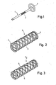
- FIG. 1 part of a steering device of an automobile is shown schematically.
- the steering device consists of a safety steering column 1, the upper end of which is connected to a hand steering wheel 2 and the lower end of which extends into a steering gear (not shown).
- the steering column In its central area, the steering column has a safety sleeve 3 made of fiber-reinforced plastic, which is designed as a lattice tube.
- the remaining parts of the steering column are of conventional construction and are connected coaxially to the safety sleeve 3 by means not shown here.
- FIG. 2 shows a security sleeve 3 1 with a circular cross section.
- the security sleeve is produced by winding fiber strands or rovings impregnated with a synthetic resin binder onto a winding mandrel with a circular cross section according to known techniques.
- the two end sides of the security sleeve are provided with a continuous edge 4 made of fiber-reinforced plastic, between which an open net-shaped structure in the form of a lattice tube extends. This space tube corresponds to a multiple winding pattern with no degree of progress.
- FIG. 4 shows a development of a part of the trellis pattern from intersecting fiber strands.
- each grid strand is composed of several, in this case four layers of flat, impregnated fiber strands 6.
- the longitudinal stiffness of the safety sleeve and thus the safety steering column can be varied by varying the cross section of the lattice strands without significantly influencing the torsional stiffness of the safety sleeve.
- the lattice strands 5 are composed of four layers of flat fiber strands 6, according to FIG. 6B the lattice strands 5 'are also composed of four layers of relatively narrow but strong fiber strands 6'.
- one half of the grid strands 5 runs at an angle ⁇ of + 45 ° with respect to the longitudinal axis 7 of the security sleeve, while the other half of the grid strands runs at an angle of -45 ° to the longitudinal axis 7.
- the safety sleeves are wound in such a way that the fiber strands of the lattice strands 5 with a positive orientation designated by 6 + in FIGS Alternate negative angle orientation.
- the stiffness of the safety sleeve and thus of the safety steering column can also be influenced by the number of layers and the cross section of the fiber strands at the crossing points.
- FIG. 5A four flat but relatively wide fiber strands 6 are used for the grid strands
- FIG. 5B likewise four, but relatively narrow and thick fiber strands 6 'are used for each grid strand.
- there is a relatively large shear area in the embodiment according to FIG. 5B a relatively small shear area, which is shown in dashed lines in this figure.
- a second embodiment of a security sleeve 3 2 which has a cross section of a regular Octagon.
- the security sleeve is wound from fiber strands on a mandrel also with an octagonal cross section, in such a way that the crossing points of the grid strands 5 come to rest on the edges of the mandrel.
- the crossing points 8 of the lattice strands each lie on a line that corresponds to an edge of the polygonal sleeve.
- the lattice strands between each two neighboring crossing points are straight and all of them run in one plane.
- FIG. 4 shows the load force F which occurs during normal operation of the longitudinal column and which acts in the longitudinal direction of the lattice strands.
- this loading force is approximately maintained, so that it also lies in the longitudinal axis of the straight lattice strands.
- the force F has a component perpendicular to the longitudinal axis of the grid strands due to the slightly curved profile of the grid strands 5.
- FIG. 4 the deformation of some lattice strands in the event of an automobile crash is shown in broken lines.
- a safety steering column according to the invention can be adapted to the safety requirements desired for each special case by a corresponding construction made of fiber-reinforced plastic and appropriate dimensioning.
- the manufacture of a steering column according to the invention is simple and inexpensive; in addition, the steering column is light in weight due to the material used.
Abstract
Eine Lenksäule (1) für Automobile, mit der die Sicherheitsanforderungen bei einem Aufprallunfall sehr einfach und genau erfüllt werden, besteht teilweise aus einer als Gitterrohr ausgebildeten Sicherheitshülse. Die Sicherheitshülse (3) ist dabei als Wickelkörper aus faserverstärktem Kunststoff mit Gittersträngen aus in kreuzweisen Lagen gewickelten mit Kunstharz getränkten Fasersträngen ausgebildet.A steering column (1) for automobiles, with which the safety requirements in the event of a collision can be met very easily and precisely, partially consists of a safety sleeve designed as a tubular grating. The safety sleeve (3) is designed as a winding body made of fiber-reinforced plastic with lattice strands made of fiber strands wound in crosswise layers and impregnated with synthetic resin.
Description
Die Erfindung bezieht sich auf eine Sicherheitslenksäule für Automobile gemäß dem Oberbegriff des Patentanspruches 1.The invention relates to a safety steering column for automobiles according to the preamble of claim 1.
Lenksäulen müssen heute aufgrund der bestehenden Sicherheitsvorschriften so gestaltet werden, daß sie die beim Fahrbetrieb des Automobils auftretenden Torsionsmomente möglichst verwindungsarm übertragen, sich bei einem Aufprallunfall jedoch in Längsrichtung verformen können. Die von der Lenksäule bei der Verformung aufgenommene Arbeit muß im Anfangsbereich der Verformung reversibel zurückgegeben werden, wobei die Lenksäule funktionsfähig bleiben muß. Bei größer werdender Längsverformung darf die Lenksäule brechen. Die den Bruch verursachende Kraft darf jedoch einen definierten Maximalwert nicht übersteigen, da sonst bei einem Aifprallunfall der Fahrer des Automobils verletzt werden kann.Due to the existing safety regulations, steering columns today have to be designed in such a way that they transmit the torsional moments that occur when the automobile is in motion, with as little torsion as possible, but can deform lengthways in the event of an impact. The work taken up by the steering column during the deformation must be reversibly returned in the initial area of the deformation, the steering column remaining functional. The steering column may break if the longitudinal deformation increases. However, the force causing the break may not exceed a defined maximum value, since otherwise the driver of the automobile may be injured in the event of an accident.
Die in der Praxis verwendeten Lösungen für Sicherheitslenksäulen basieren im wesentlichen auf zwei Prinzipien:
- Bei dem einen Prinzip ist die Sicherheitslenksäule aus zwei gegeneinander längs verschiebbaren, jedoch drehmomentformschlüssig verbundenen Teilen aufgebaut. Bei einem Aufprallunfall wird auf die beiden Lenksäulenteile eine gegeneinander gerichtete Längskraft ausgeübt, aufgrund der die beiden Teile sich relativ zueinander verschieben, so daß die Lenksäule insgesamt verkürzt wird. Ab einer gewissen Verkürzung werden die beiden Teile voneinander getrennt und sozusagen ausgeklinkt. Die Lenksäulenteile sind so konstruiert, daß sie nach dem Ausklinken aneinander vorbei oder in Art von Teleskoprohren ineinandergleiten.
- In one principle, the safety steering column is made up of two parts which can be moved longitudinally but are connected in a torque-locking manner. In the event of an impact, the two steering column parts are mutually opposed directed longitudinal force exerted, due to which the two parts move relative to each other, so that the steering column is shortened overall. After a certain shortening, the two parts are separated from each other and released, so to speak. The steering column parts are designed so that after they have been released they slide past one another or slide into one another in the manner of telescopic tubes.
Sicherheitslenksäulen nach diesem Prinzip erfordern eine aufwendige und daher teuere Konstruktion.Safety steering columns based on this principle require a complex and therefore expensive construction.
Bei dem zweiten in der Praxis verwendeten Konstruktionsprinzip für Sicherheitslenksäulen werden die elastischen und plastischen Eigenschaften metallischer Werkstoffe ausgenutzt. Die Sicherheitslenksäulen sind hier zumindest in den sich bei einem Aufprallunfall verkürzenden Be2eLch aus einem metallischen Gitter-oder Wellrohr gefertigt. Die Gitter- und Wellrohre müssen äußerst genau gefertigt werden, da die oben genannten Sicherheitsanforderungen möglichst exakt, d.h. quasi ohne Toleranzen eingehalten werden müssen. Die Fertigung derartiger Sicherheitsrohre für Lenksäulen ist aus diesen genannten Gründen sehr schwierig und aufwendig. Außerdem haben selbst Gitterrohre ein sehr hohes Gewicht, damit die bei Lenkbewegungen auftretenden Torsionskräfte verwindungsarm übertragen werden können.The second construction principle used in practice for safety steering columns uses the elastic and plastic properties of metallic materials. The safety steering columns here are made, at least in the Be2eLch, which are shortened in the event of an impact, from a metallic grid or corrugated tube. The grid and corrugated pipes must be manufactured extremely precisely, since the above-mentioned safety requirements are as precise as possible, i.e. must be complied with virtually without tolerances. The production of such safety tubes for steering columns is very difficult and expensive for these reasons. In addition, even lattice tubes have a very high weight so that the torsional forces occurring during steering movements can be transmitted with little torsion.
Der Erfindung liegt die Aufgabe zugrunde, eine Lenksäule mit einer als Gitterrohr ausgebildeten Sicherheitshülse anzugeben, die einfach zu fertigen ist und mit der die Sicherheitsanforderungen sehr einfach und genau erfüllt werden.The invention has for its object to provide a steering column with a safety sleeve designed as a grid tube, which is easy to manufacture and with which the safety requirements are met very easily and accurately.
Diese Aufgabe ist gemäß der Erfindung durch im Kennzeichen des Patentanspruches 1 angegebenen Merkmale gelöst. Gemäß der Erfindung wird demnach die Lenksäule oder zumindest der als Sicherheitshülse bezeichnete, sich bei einem Aufprallunfall verkürzende Bereich aus faserverstärktem Kunststoff gewickelt. Die Sicherheitshülse wird hierzu nach ansich bekanntem Verfahren auf einen Wickeldorn aus einem oder mehreren getränkten Fasersträngen gewickelt, ausgehärtet und anschließend vom Wickeldorn abgezogen. Bei der Fertigung dieses Wickelkörpers werden die spezifischen Eigenschaften von Faserverbundwerkstoffen ausgenützt, und zwar vor allem die entsprechend dem gewählten Wickelvorgang richtungsabhängige Belastbarkeit des Wickelkörpers und die ebenfalls durch den Wickelvorgang mögliche Auslegung der Sicherheitshülse hinsichtlich ganz bestimmter gewünschter Eigenschaften. In Kombination mit dem auf das Material abgestellten Fertigungsverfahren können auf diese Weise Sicherheitslenksäulen hergestellt werden, die die oben genannten geforderten Eigenschaften präzise erfüllen, dabei aber relativ leicht sind sowie kostengünstig produziert werden können.This object is achieved according to the invention by the features specified in the characterizing part of patent claim 1. According to the invention, the steering column or at least the area referred to as the safety sleeve, which is shortened in the event of an impact, is wound from fiber-reinforced plastic. For this purpose, the security sleeve is made according to a known method wound on a mandrel from one or more impregnated fiber strands, cured and then removed from the mandrel. In the manufacture of this winding body, the specific properties of fiber composite materials are used, in particular the directional load-bearing capacity of the winding body in accordance with the selected winding process and the design of the security sleeve also possible by the winding process with regard to very specific desired properties. In combination with the manufacturing process based on the material, safety steering columns can be produced in this way that precisely meet the above-mentioned properties, but are relatively light and can be produced inexpensively.
Die aus einzelnen Fasersträngen in mehreren Lagen übereinander gewickelten Gitterstränge der gitterrohrförmigen Sicherheitshülse weisen bevorzugt einen Orientierungswinkel gegenüber der Längsachse der Sicherheitshülse von - 45° auf. An den Kreu- zungspunkten der Gitterstränge sind die Faserstränge des in der +45°-Orientierung verlaufenden Gitterstranges und die Faserstränge des in der -45°-Orientierung verlaufenden Gitterstranges in abwechselnden Lagen übereinander gewickelt, so daß an diesen Punkten quasi eine Verzahnung der einzelnen Gitterstränge erfolgt.The lattice strands of the lattice-tube-shaped security sleeve, which are wound one above the other from individual fiber strands in several layers, preferably have an orientation angle of −45 ° with respect to the longitudinal axis of the security sleeve. At the crossing points of the lattice strands, the fiber strands of the lattice strand running in the + 45 ° orientation and the fiber strands of the lattice strand running in the -45 ° orientation are wound one above the other in alternate layers, so that at these points the individual lattice strands are virtually interlocked he follows.
Die Anforderungen an die Steifigkeit der Sicherheitssäule können in weiten Bereichen variiert werden, und zwar z. B. durch die Anzahl der Faserstranglagenbei den einzelnen Gittersträngen oder durch die Wahl der Breite der gewickelten Faserstränge sowie durch den Orientierungswinkel, den die gewickelten Gitterstränge gegenüber der Längsachse der Sicherheitshülse einnehmen.The requirements for the rigidity of the safety pillar can be varied in a wide range, for. B. by the number of fiber strand layers in the individual lattice strands or by the choice of the width of the wound fiber strands and by the orientation angle which the wound lattice strands make with respect to the longitudinal axis of the security sleeve.
Die Orientierung der auf einem Dorn aufgewickelten Faserstränge ist im Grunde frei wählbar, wird sinnvollerweise aber so gewählt, daß bei einer optimalen Torsionssteifigkeit und Torsionsfestigkeit eine möglichst niedrige Längssteifigkeit und Längsfestigkeit der Sicherheitshülse erreicht wird. Dieses Optimum liegt bei einem Orientierungswinkel von ±45°, weil nur dann die einzelnen Gitterstränge zwischen den Kreuzungspunkten bei Torsion auf Zug und Druck, bei einer Längskraft aber auf Biegung und Scherung beansprucht werden. Bei Torsionskräften hat die Sicherheitshülse demnach eine hohe, bei Längskräften eine niedrige Steifigkeit.The orientation of the fiber strands wound on a mandrel is basically freely selectable, but is expediently chosen in such a way that with optimum torsional rigidity and torsional strength the lowest possible longitudinal stiffness and longitudinal strength of the safety sleeve is achieved. This optimum is at an orientation angle of ± 45 °, because only then are the individual lattice strands between the crossing points subjected to torsion under tension and compression, but with a longitudinal force on bending and shear. The safety sleeve therefore has a high stiffness for torsional forces and a low stiffness for longitudinal forces.
Bei einer Abweichung des Orientierungswinkels von f 45° um einige Grad, maximal um ca. 10°, kann die Steifigkeit bei Längskräften unter Umständen noch gesenkt werden, ohne daß die Torsionssteifigkeit wesentlich geringer wird. Aus diesen Gründen kann im Einzelfalle eine solche Abweichung vom Orientierungswinkel von ± 45° sinnvoll sein.If the orientation angle deviates from f 45 ° by a few degrees, at most by approximately 10 °, the stiffness under longitudinal forces can be reduced under certain circumstances without the torsional stiffness becoming significantly lower. For these reasons, such a deviation from the orientation angle of ± 45 ° can make sense in individual cases.
Die Festigkeit sowie auch die Steifigkeit der einzelnen Gitterstränge ist bei Belastung in Längsrichtung sehr viel größer als bei Biegebelastung, wo das Aufbrechen der Gitterstränge durch interlaminaren Schubbruch ausgelöst wird. Diese Tendenz zum gewünschten Versagen in Längsrichtung kann dadurch erhöht werden, daß bei einer offenen Netzwicklung der Sicherheitshülse die Schubflächen zwischen den in +45-Orientierung und den in -45°-Orientierung verlaufenden Gittersträngen stark vermindert werden und somit an den Kreuzungspunkten bei Längsbelastung der Sicherheitshülse das gewünschte frühzeitige Versagen eintritt.The strength as well as the rigidity of the individual lattice strands is much greater when loaded in the longitudinal direction than with bending loads, where the breaking of the lattice strands is triggered by interlaminar shear fracture. This tendency towards the desired failure in the longitudinal direction can be increased in that with an open network winding of the safety sleeve, the shear areas between the grid strands running in + 45 orientation and in - 45 ° orientation are greatly reduced and thus at the crossing points when the safety sleeve is loaded longitudinally the desired early failure occurs.
Das Verhältnis von Höhe und Breite der einzelnen Gitterstränge kann an die gewünschten Anforderungen z. B. durch Wahl von Fasersträngen mit verschiedener Breite in Kombination mit der Zahl der Wickellagen variieren. Auch mit dieser Möglichkeit kann die Längssteifigkeit der Sicherheitshülse verändert werden, ohne daß die Torsionssteifigkeit bzw. Festigkeit allzu stark beeinflußtwird, da die Längsfestigkeit der einzelnen Gitterstränge auf Zug und Druck nur von deren Querschnitt abhängig, d.h. unabhängig vom Verhältnis Höhe zu Breite ist.The ratio of height and width of the individual lattice strands can z. B. vary by choosing fiber strands with different widths in combination with the number of winding layers. Even with this possibility, the longitudinal stiffness of the safety sleeve can be changed without the torsional stiffness or strength being influenced too much, since the longitudinal strength of the individual lattice strands on tension and compression only depends on their cross-section, i.e. is independent of the ratio of height to width.
Die Sicherheitshülse kann z. B. einen kreisförmigen Querschnitt aufweisen, d.h. die einzelnen Faserstränge werden auf einen runden Dorn aufgewickelt. Die einzelnen Gitterstränge der Sicherheitshülse sind in diesem Falle leicht gekrümmt, so daß die Torsionsbelastungen nicht nur in Längsrichtung der einzelnen Gitterstränge verlaufen, sondern auch eine Komponente senkrecht zu den Gitterstäben aufweisen. Um bei extremen Torsionsbelastungen ein Knicken einzelner Gitterstränge zu vermeiden, können diese bei der Wicklung entsprechend dimensioniert sein.The security sleeve can, for. B. have a circular cross-section, i.e. the individual fiber strands are wound on a round mandrel. The individual lattice strands of the security sleeve are slightly curved in this case, so that the torsional loads not only run in the longitudinal direction of the individual lattice strands, but also have a component perpendicular to the lattice bars. In order to avoid kinking of individual lattice strands in the case of extreme torsional loads, these can be dimensioned accordingly in the winding.
Vorzugsweise wird die Sicherheitshülse jedoch auf einem Dorn mit dem Querschnitt eines regelmäßigen Polygons gewickelt, so daß auch die Sicherheitshülse den Querschnitt eines regelmäßigen Polygons aufweist. Die Faserstränge werden bei der Wicklung so abgelegt, daß die Kreuzungspunkte auf den Kanten des Dornes liegen, das heißt bei der fertigen Sicherheitshülse auf den Polygonkanten liegen. Bei einer derartig gewickelten Sicherheitshülse sind die einzelnen Gitterstränge zwischen zwei Kreuzungspunkten gerade Stäbe, die bei Torsionsbelastung annähernd ausschließlich in der Längsachse beansprucht werden und erst bei wesentlich höheren Torsionsbelastungen knickgefährdet sind als die leichtgekrümmten Gitterstäbe einer Sicherheitshülse mit kreisförmigen Querschnitt.However, the security sleeve is preferably wound on a mandrel with the cross section of a regular polygon, so that the security sleeve also has the cross section of a regular polygon. During the winding, the fiber strands are deposited in such a way that the crossing points lie on the edges of the mandrel, that is to say on the polygon edges in the finished safety sleeve. With a security sleeve wound in this way, the individual lattice strands between two crossing points are straight bars that are almost exclusively stressed in the longitudinal axis under torsional loads and are only at risk of kinking at significantly higher torsional loads than the slightly curved lattice bars of a security sleeve with a circular cross-section.
Die Erfindung ist in zwei Ausführungsbeispielen anhand der Zeichnung näher erläutert. In der Zeichnung stellen dar:
- Figur 1 eine schematische Darstellung einer Sicherheitslenksäule gemäß der Erfindung mit einer, einen Teil der Lenksäule bildenden Sicherheitshülse aus faserverstärktem Kunststoff;
Figur 2 eine erste Ausführungsform einer Sicherheitshülse aus faserverstärktem Kunststoff für eine Sicherheitslenksäule gemäß der Erfindung;Figur 3 eine zweite Ausführungsform einer Sicherheitshülse aus faserverstärktem Kunststoff für eine Sicherheitslenksäule gemäß der Erfindung;Figur 4 einen Teil einer Abwicklung der Wand einer Sicherheitshülse gemäß der Erfindung;- Figuren 5A jeweils einen Querschnitt entsprechend u. 5B den Linien V-V in
Figur 4; - Figuren 6A jeweils einen Querschnitt längs den Linien u. 6B VI-VI in
Figur 4.
- Figure 1 is a schematic representation of a safety steering column according to the invention with a safety sleeve forming part of the steering column made of fiber-reinforced plastic;
- FIG. 2 shows a first embodiment of a safety sleeve made of fiber-reinforced plastic for a safety steering column according to the invention;
- FIG. 3 shows a second embodiment of a safety sleeve made of fiber-reinforced plastic for a safety steering column according to the invention;
- Figure 4 shows part of a development of the wall of a safety sleeve according to the invention;
- Figures 5A each have a cross section corresponding u. 5B the lines VV in Figure 4;
- Figures 6A each have a cross section along the lines u. 6B VI-VI in Figure 4.
In Figur 1 ist schematisch ein Teil einer Lenkeinrichtung eines Automobiles dargestellt. Die Lenkeinrichtung besteht aus einer Sicherheitslenksäule 1, deren oberes Ende mit einem Handlenkrad 2 verbunden ist und dessen unteres Ende in ein nicht dargestelltes Lenkgetriebe reicht. Die Lenksäule weist etwa in ihrem mittleren Bereich eine als Gitterrohr ausgebildete Sicherheitshülse 3 aus faserverstärktem Kunststoff auf. Die übrigen Teile der Lenksäule sind von herkömmlicher Bauart und mit hier nicht dargestellten Mitteln mit der Sicherheitshülse 3 koaxial verbunden.In Figure 1, part of a steering device of an automobile is shown schematically. The steering device consists of a safety steering column 1, the upper end of which is connected to a
In Figur 2 ist eine Sicherheitshülse 31 mit kreisförmigem Querschnitt dargestellt. Die Sicherheitshülse wird dadurch hergestellt, daß mit einem Kunstharz-Bindemittel getränkte Faserstränge bzw. Rovings auf einen im Querschnitt kreisförmigen Wickeldorn nach bekannten Techniken aufgewickelt werden. Die beiden Endseiten der Sicherheitshülse sind mit einem durchgehenden Rand 4 aus faserverstärktem Kunststoff versehen, zwischen denen sich eine offene netzförmige Struktur in Form eines Gitterrohres erstreckt. Dieses Gitterrohr entspricht einem Mehrfach-Wickelmuster ohne Fortschrittsgrad. In Figur 4 ist eine Abwicklung eines Teiles des Gitterrohrmusters aus sich überkreuzenden Fasersträngen dargestellt. Die Elemente des Gitterrohrs zwischen jeweils zwei Kreuzungspunkten werden mit Gittersträngen 5 bezeichnet. Aus den Figuren 6A und 6B ist zu entnehmen, daß jeder Gitterstrang aus mehreren, in diesem Falle vier Lagen von flachen getränkten Fasersträngen 6 zusammengesetzt ist. Entsprechend den Sicherheitsanforderungen kann die Längssteifigkeit der Sicherheitshülse und damit der Sicherheitslenksäule durch Variation des Querschnittes der Gitterstränge variiert werden, ohne daß dadurch wesentlich die Torsionssteifigkeit der Sicherheitshülse beeinflußtwird. Gemäß Figur 6A sind die Gitterstränge 5 aus vier Lagen flacher Faserstränge 6, gemäß Figur 6B die Gitterstränge 5' aus ebenfalls vier Lagen verhältnismäßig schmaler, jedoch starker Faserstränge 6' zusammengesetzt.FIG. 2 shows a
Wie aus Figur 4 hervorgeht, verläuft eine Hälfte der Gitterstränge 5 unter einem Winkel α von +45° in Bezug zu der Längsachse 7 der Sicherheitshülse, während die andere Hälfte der Gitterstränge unter einem Winkel von -45° zur Längsachse 7 verläuft. An den Kreuzungspunkten 8 der Gitterstränge mit positiver Winkelorientierung und der Gitteistränge mit negativer Winkelorientierung sind die Sicherheitshülsen so gewickelt, daß die in den Figuren 5A und 5B mit 6+ bezeichneten Faserstränge der Gitterstränge 5 mit positiver Orientierung mit den mit den Bezugszeichen 6_ bezeichneten Fasersträngen derGitterstränge mit negativer Winkelorientierung abwechseln. Auch an den Kreuzungspunkten kann die Steifigkeit der Sicherheitshülse und damit der Sicherheitslenksäule durch Anzahl der Lagen und den Querschnitt der Faserstränge beeinflußtwerden. Gemäß Figur 5A werden für die Gitterstränge jeweils vier flache, jedoch verhältnismäßig breite Faserstränge 6 verwendet, gemäß Figur 5B ebenfalls für jeden Gitterstrang vier, jedoch verhältnismäßig schmale und dicke Faserstränge 6' verwendet. Bei der Ausführung gemäß Fig.5A ergibt sich demnach eine verhältnismäßig große Schubfläche, bei der Ausführungsform gemäß Figur 5B eine relativ kleine Schubfläche, die in dieser Figur gestrichelt dargestellt ist.As can be seen from FIG. 4, one half of the
In Figur 3 ist eine zweite Ausführungsform einer Sicherheitshülse 32 dargestellt, die einen Querschnitt eines regelmäßigen Achteckes aufweist. Die Sicherheitshülse ist aus Fasersträngen auf einen Dorn mit ebenfalls achteckigem Querschnitt gewickelt, und zwar derart, daß die Kreuzungspunkte der Gitterstränge 5 auf den Kanten des Dornes zu liegen kommen. Bei der fertigen Sicherheitshülse liegen dann die Kreuzungspunkte 8 der Gitterstränge jeweils auf einer Linie, die einer Kante der mehreckigen Hülse entspricht. Die Gitterstränge zwischen jeweils zwei benachbarten Kreuzungspunkten sind gerade und sämtlich in einer Ebene verlaufende Stäbe.In Figure 3, a second embodiment of a
In-Figur 4 ist die bei normalem Betrieb der Längssäule auftretende Belastungskraft F dargestellt, die in Längsrichtung der Gitterstränge wirkt. Bei dem Ausführungsbeispiel gemäß der Figur 3 bleibt diese Belastungskraft annähernd erhalten, so daß sie ebenfalls in der Längsachse der geraden Gitterstränge liegt. Bei dem Ausführungsbeispiel gemäß Figur 2 hat die Kraft F aufgrund des leicht gekrümmten Verlaufes der Gitterstränge 5 noch eine Komponente senkrecht zu der Längsachse der Gitterstränge.FIG. 4 shows the load force F which occurs during normal operation of the longitudinal column and which acts in the longitudinal direction of the lattice strands. In the exemplary embodiment according to FIG. 3, this loading force is approximately maintained, so that it also lies in the longitudinal axis of the straight lattice strands. In the exemplary embodiment according to FIG. 2, the force F has a component perpendicular to the longitudinal axis of the grid strands due to the slightly curved profile of the
In Figur 4 ist gestrichelt für einige Gitterstränge deren Verformung bei einem Aufprallunfall des Automobils dargestellt.In FIG. 4, the deformation of some lattice strands in the event of an automobile crash is shown in broken lines.
Eine Sicherheitslenksäule gemäß der Erfindung kann durch entsprechende Konstruktion aus faserverstärkteM Kunststoff und entsprechende Dimensionierung an die für jeden speziellen Fall gewünschten Sicherheitsanforderungen angepaßt werden. Die Herstellung einer Lenksäule gemäß der Erfindung ist einfach und kostengünstig; außerdem hat die Lenksäule aufgrund des verwendeten Werkstoffes nur ein geringes Gewicht.A safety steering column according to the invention can be adapted to the safety requirements desired for each special case by a corresponding construction made of fiber-reinforced plastic and appropriate dimensioning. The manufacture of a steering column according to the invention is simple and inexpensive; in addition, the steering column is light in weight due to the material used.
Claims (5)
Applications Claiming Priority (2)
| Application Number | Priority Date | Filing Date | Title |
|---|---|---|---|
| DE3045141A DE3045141C2 (en) | 1980-11-29 | 1980-11-29 | Safety steering column for motor vehicles |
| DE3045141 | 1980-11-29 |
Publications (2)
| Publication Number | Publication Date |
|---|---|
| EP0053284A1 true EP0053284A1 (en) | 1982-06-09 |
| EP0053284B1 EP0053284B1 (en) | 1985-05-02 |
Family
ID=6117965
Family Applications (1)
| Application Number | Title | Priority Date | Filing Date |
|---|---|---|---|
| EP81109082A Expired EP0053284B1 (en) | 1980-11-29 | 1981-10-28 | Safety steering column for automobiles |
Country Status (4)
| Country | Link |
|---|---|
| US (1) | US4465301A (en) |
| EP (1) | EP0053284B1 (en) |
| JP (1) | JPS57114760A (en) |
| DE (1) | DE3045141C2 (en) |
Cited By (6)
| Publication number | Priority date | Publication date | Assignee | Title |
|---|---|---|---|---|
| EP0091671A2 (en) * | 1982-04-10 | 1983-10-19 | Audi Ag | Safety steering column for motor vehicles |
| FR2547259A1 (en) * | 1983-06-11 | 1984-12-14 | Messerschmitt Boelkow Blohm | SAFETY STEERING COLUMN OF PLASTIC MATERIALS FIBER-REINFORCED AND WRAPPED |
| EP0130009A1 (en) * | 1983-06-18 | 1985-01-02 | Ford Motor Company Limited | Energy absorption arrangement |
| FR2558105A1 (en) * | 1983-06-11 | 1985-07-19 | Messerschmitt Boelkow Blohm | TUBE, ESPECIALLY FOR A SAFETY STEERING COLUMN FOR MOTOR VEHICLES |
| EP0165394A1 (en) * | 1984-05-23 | 1985-12-27 | Messerschmitt-Bölkow-Blohm Gesellschaft mit beschränkter Haftung | Element for transmitting torques |
| DE102015100797A1 (en) | 2015-01-20 | 2016-07-21 | Ford-Werke Gmbh | plastic steering column |
Families Citing this family (15)
| Publication number | Priority date | Publication date | Assignee | Title |
|---|---|---|---|---|
| DE3049425C2 (en) * | 1980-12-30 | 1991-09-05 | Messerschmitt-Bölkow-Blohm GmbH, 8000 München | Impact protection component |
| JPS5981253A (en) * | 1982-11-02 | 1984-05-10 | Mitsubishi Electric Corp | Shock absorbing steering shaft |
| JPS6164581A (en) * | 1984-09-06 | 1986-04-02 | Toyota Motor Corp | Steering wheel made of fiber reinforced resin |
| DE3520251A1 (en) * | 1985-06-05 | 1986-12-11 | Metzeler Kautschuk GmbH, 8000 München | DEFORMABLE DRIVE SHAFT |
| DE3520252A1 (en) * | 1985-06-05 | 1986-12-11 | Metzeler Kautschuk GmbH, 8000 München | DRIVE SHAFT |
| DE3836685C1 (en) * | 1988-10-28 | 1990-01-25 | Audi Ag, 8070 Ingolstadt, De | Safety steering column for motor vehicles |
| DE3838594A1 (en) * | 1988-11-15 | 1990-05-17 | Kolbenschmidt Ag | INSTALLATION COMPONENT FOR ABSORPTION OF ENERGY |
| DE10000286A1 (en) * | 2000-01-07 | 2001-07-26 | Wagon Automotive Gmbh | Impact absorber |
| GB2368894B (en) * | 2000-11-14 | 2005-07-20 | Nastech Europ Ltd | Steering column assembly for a vehicle |
| US6692026B2 (en) * | 2001-09-13 | 2004-02-17 | Visteon Global Technologies, Inc. | Polymer composite steering column support housing and assembly |
| FR2857323B1 (en) * | 2003-07-11 | 2005-09-02 | Nacam | EVOLUTIVE POWER ABSORPTION DEVICE OF A STEERING COLUMN OF A MOTOR VEHICLE |
| US20050167963A1 (en) * | 2004-01-30 | 2005-08-04 | Mirjana Jurik | Energy absorbing steering column geometric sleeve |
| DE102016221462A1 (en) | 2016-11-02 | 2018-05-03 | Ford Global Technologies, Llc | Crumple element for a safety steering column |
| DE202017100169U1 (en) | 2016-11-02 | 2017-03-27 | Ford Global Technologies, Llc | Crumple element for a safety steering column |
| DE102016221461B4 (en) | 2016-11-02 | 2020-07-16 | Ford Global Technologies, Llc | Crumple element for a safety steering column |
Citations (4)
| Publication number | Priority date | Publication date | Assignee | Title |
|---|---|---|---|---|
| FR1020948A (en) * | 1950-06-26 | 1953-02-12 | Soft diection for automobiles | |
| DE1298010B (en) * | 1966-06-04 | 1969-06-19 | Volkswagenwerk Ag | Safety steering column for motor vehicles |
| DE2210809A1 (en) * | 1971-03-10 | 1972-09-14 | Societe Quillery, La Garenne Colom bes, Hauts de Seine (Frankreich) | Energy absorption device |
| DE2918280A1 (en) * | 1978-05-10 | 1979-11-22 | Textron Inc | SHOCK ABSORBING DEVICE |
Family Cites Families (10)
| Publication number | Priority date | Publication date | Assignee | Title |
|---|---|---|---|---|
| US3373629A (en) * | 1966-04-29 | 1968-03-19 | Gen Motors Corp | Steering column assembly |
| US3564688A (en) * | 1966-07-14 | 1971-02-23 | Koppy Tool Corp | Method for forming a shock absorbing structural member |
| US3495474A (en) * | 1966-11-24 | 1970-02-17 | Nissan Motor | Impact absorbing means for vehicles |
| US3482466A (en) * | 1967-01-24 | 1969-12-09 | Helmut Orlich | Torsion device for steering columns |
| US3508633A (en) * | 1967-05-17 | 1970-04-28 | Nissan Motor | Plastically deformable impact absorbing means for vehicles |
| JPS492728B1 (en) * | 1968-12-17 | 1974-01-22 | ||
| DE2150061C3 (en) * | 1971-10-07 | 1975-08-07 | Adam Opel Ag, 6090 Ruesselsheim | Plastically deformable deformation member made of sheet metal for safety steering of motor vehicles |
| US3983963A (en) * | 1972-09-22 | 1976-10-05 | Nissan Motor Co., Ltd. | Multifacially formed panel impact absorber |
| JPS5018248A (en) * | 1973-06-13 | 1975-02-26 | ||
| DE2738074A1 (en) * | 1976-05-26 | 1979-03-08 | Porsche Ag | DEFORMING LINK FOR A MOTOR VEHICLE |
-
1980
- 1980-11-29 DE DE3045141A patent/DE3045141C2/en not_active Expired
-
1981
- 1981-10-28 EP EP81109082A patent/EP0053284B1/en not_active Expired
- 1981-11-20 US US06/323,357 patent/US4465301A/en not_active Expired - Fee Related
- 1981-11-28 JP JP56189918A patent/JPS57114760A/en active Granted
Patent Citations (4)
| Publication number | Priority date | Publication date | Assignee | Title |
|---|---|---|---|---|
| FR1020948A (en) * | 1950-06-26 | 1953-02-12 | Soft diection for automobiles | |
| DE1298010B (en) * | 1966-06-04 | 1969-06-19 | Volkswagenwerk Ag | Safety steering column for motor vehicles |
| DE2210809A1 (en) * | 1971-03-10 | 1972-09-14 | Societe Quillery, La Garenne Colom bes, Hauts de Seine (Frankreich) | Energy absorption device |
| DE2918280A1 (en) * | 1978-05-10 | 1979-11-22 | Textron Inc | SHOCK ABSORBING DEVICE |
Cited By (9)
| Publication number | Priority date | Publication date | Assignee | Title |
|---|---|---|---|---|
| EP0091671A2 (en) * | 1982-04-10 | 1983-10-19 | Audi Ag | Safety steering column for motor vehicles |
| EP0091671A3 (en) * | 1982-04-10 | 1984-04-25 | Audi Nsu Auto Union Aktiengesellschaft | Safety steering column for motor vehicles |
| FR2547259A1 (en) * | 1983-06-11 | 1984-12-14 | Messerschmitt Boelkow Blohm | SAFETY STEERING COLUMN OF PLASTIC MATERIALS FIBER-REINFORCED AND WRAPPED |
| FR2558105A1 (en) * | 1983-06-11 | 1985-07-19 | Messerschmitt Boelkow Blohm | TUBE, ESPECIALLY FOR A SAFETY STEERING COLUMN FOR MOTOR VEHICLES |
| EP0130009A1 (en) * | 1983-06-18 | 1985-01-02 | Ford Motor Company Limited | Energy absorption arrangement |
| EP0165394A1 (en) * | 1984-05-23 | 1985-12-27 | Messerschmitt-Bölkow-Blohm Gesellschaft mit beschränkter Haftung | Element for transmitting torques |
| DE102015100797A1 (en) | 2015-01-20 | 2016-07-21 | Ford-Werke Gmbh | plastic steering column |
| US9919728B2 (en) | 2015-01-20 | 2018-03-20 | Ford-Werke Gmbh | Steering column made of plastic |
| DE102015100797B4 (en) * | 2015-01-20 | 2021-01-07 | Ford-Werke Gmbh | Plastic steering column |
Also Published As
| Publication number | Publication date |
|---|---|
| JPH0134183B2 (en) | 1989-07-18 |
| US4465301A (en) | 1984-08-14 |
| EP0053284B1 (en) | 1985-05-02 |
| DE3045141A1 (en) | 1982-06-24 |
| DE3045141C2 (en) | 1987-07-09 |
| JPS57114760A (en) | 1982-07-16 |
Similar Documents
| Publication | Publication Date | Title |
|---|---|---|
| DE3045141C2 (en) | Safety steering column for motor vehicles | |
| DE3049425C2 (en) | Impact protection component | |
| DE2611235C2 (en) | Rotor blades for rotary wing aircraft, in particular helicopters | |
| EP2082131B2 (en) | Mast for a wind turbine | |
| EP1948960B1 (en) | Leaf spring consisting of a fibre-composite material | |
| DE2942519C2 (en) | ||
| DE1755897A1 (en) | Rubber spring element for vehicle suspension or the like. | |
| DE2757965A1 (en) | THROTTLE TRANSMISSION ELEMENT AND METHOD FOR MANUFACTURING IT | |
| DE19955755C2 (en) | Motor vehicle with a reinforcement structure of a side longitudinal member | |
| DE3321198C1 (en) | Safety steering column made of wound fiber-reinforced plastics | |
| AT392525B (en) | LEAF SPRING MADE OF FIBER-PLASTIC COMPOSITE | |
| DE2614691C3 (en) | Caterpillar | |
| EP3723963B1 (en) | Method for producing a component, and component | |
| DE2907528C2 (en) | ||
| DE2212713B2 (en) | SAFETY STEERING COLUMN FOR VEHICLES, IN PARTICULAR MOTOR VEHICLES | |
| EP0108870A1 (en) | Bumper bearing part made of fibre-reinforced material for motor vehicles or the like | |
| DE3321197C2 (en) | Tube, in particular for a safety steering column for motor vehicles | |
| DE3419176C2 (en) | ||
| DE3146261C2 (en) | ||
| DE4425829C1 (en) | Helicopter structural element in sandwich form | |
| DE3302770A1 (en) | Energy-absorbing laminate | |
| DE2904439C2 (en) | ||
| DE2201952A1 (en) | IMPACT ABSORBING ELEMENT, IN PARTICULAR FOR MOTOR VEHICLES | |
| EP0033143A1 (en) | Process for manufacturing turnbuckles | |
| DE19604275C2 (en) | Method of manufacturing a component |
Legal Events
| Date | Code | Title | Description |
|---|---|---|---|
| PUAI | Public reference made under article 153(3) epc to a published international application that has entered the european phase |
Free format text: ORIGINAL CODE: 0009012 |
|
| AK | Designated contracting states |
Designated state(s): FR GB IT |
|
| 17P | Request for examination filed |
Effective date: 19820403 |
|
| ITF | It: translation for a ep patent filed |
Owner name: STUDIO JAUMANN |
|
| GRAA | (expected) grant |
Free format text: ORIGINAL CODE: 0009210 |
|
| AK | Designated contracting states |
Designated state(s): FR GB IT |
|
| ET | Fr: translation filed | ||
| PLBE | No opposition filed within time limit |
Free format text: ORIGINAL CODE: 0009261 |
|
| STAA | Information on the status of an ep patent application or granted ep patent |
Free format text: STATUS: NO OPPOSITION FILED WITHIN TIME LIMIT |
|
| 26N | No opposition filed | ||
| PGFP | Annual fee paid to national office [announced via postgrant information from national office to epo] |
Ref country code: GB Payment date: 19900924 Year of fee payment: 10 |
|
| PGFP | Annual fee paid to national office [announced via postgrant information from national office to epo] |
Ref country code: FR Payment date: 19901009 Year of fee payment: 10 |
|
| ITTA | It: last paid annual fee | ||
| PG25 | Lapsed in a contracting state [announced via postgrant information from national office to epo] |
Ref country code: GB Effective date: 19911028 |
|
| GBPC | Gb: european patent ceased through non-payment of renewal fee | ||
| PG25 | Lapsed in a contracting state [announced via postgrant information from national office to epo] |
Ref country code: FR Effective date: 19920630 |
|
| REG | Reference to a national code |
Ref country code: FR Ref legal event code: ST |