EP0052994A2 - Improvements in or relating to setting mechanisms especially for tools for carrying out routing and like operations - Google Patents
Improvements in or relating to setting mechanisms especially for tools for carrying out routing and like operations Download PDFInfo
- Publication number
- EP0052994A2 EP0052994A2 EP81305421A EP81305421A EP0052994A2 EP 0052994 A2 EP0052994 A2 EP 0052994A2 EP 81305421 A EP81305421 A EP 81305421A EP 81305421 A EP81305421 A EP 81305421A EP 0052994 A2 EP0052994 A2 EP 0052994A2
- Authority
- EP
- European Patent Office
- Prior art keywords
- collar
- tool
- post
- further characterised
- setting
- Prior art date
- Legal status (The legal status is an assumption and is not a legal conclusion. Google has not performed a legal analysis and makes no representation as to the accuracy of the status listed.)
- Withdrawn
Links
Images

Classifications
-
- B—PERFORMING OPERATIONS; TRANSPORTING
- B27—WORKING OR PRESERVING WOOD OR SIMILAR MATERIAL; NAILING OR STAPLING MACHINES IN GENERAL
- B27C—PLANING, DRILLING, MILLING, TURNING OR UNIVERSAL MACHINES FOR WOOD OR SIMILAR MATERIAL
- B27C5/00—Machines designed for producing special profiles or shaped work, e.g. by rotary cutters; Equipment therefor
- B27C5/10—Portable hand-operated wood-milling machines; Routers
-
- B—PERFORMING OPERATIONS; TRANSPORTING
- B23—MACHINE TOOLS; METAL-WORKING NOT OTHERWISE PROVIDED FOR
- B23Q—DETAILS, COMPONENTS, OR ACCESSORIES FOR MACHINE TOOLS, e.g. ARRANGEMENTS FOR COPYING OR CONTROLLING; MACHINE TOOLS IN GENERAL CHARACTERISED BY THE CONSTRUCTION OF PARTICULAR DETAILS OR COMPONENTS; COMBINATIONS OR ASSOCIATIONS OF METAL-WORKING MACHINES, NOT DIRECTED TO A PARTICULAR RESULT
- B23Q16/00—Equipment for precise positioning of tool or work into particular locations not otherwise provided for
- B23Q16/001—Stops, cams, or holders therefor
-
- Y—GENERAL TAGGING OF NEW TECHNOLOGICAL DEVELOPMENTS; GENERAL TAGGING OF CROSS-SECTIONAL TECHNOLOGIES SPANNING OVER SEVERAL SECTIONS OF THE IPC; TECHNICAL SUBJECTS COVERED BY FORMER USPC CROSS-REFERENCE ART COLLECTIONS [XRACs] AND DIGESTS
- Y10—TECHNICAL SUBJECTS COVERED BY FORMER USPC
- Y10T—TECHNICAL SUBJECTS COVERED BY FORMER US CLASSIFICATION
- Y10T408/00—Cutting by use of rotating axially moving tool
- Y10T408/96—Miscellaneous
- Y10T408/99—Adjustable stop
-
- Y—GENERAL TAGGING OF NEW TECHNOLOGICAL DEVELOPMENTS; GENERAL TAGGING OF CROSS-SECTIONAL TECHNOLOGIES SPANNING OVER SEVERAL SECTIONS OF THE IPC; TECHNICAL SUBJECTS COVERED BY FORMER USPC CROSS-REFERENCE ART COLLECTIONS [XRACs] AND DIGESTS
- Y10—TECHNICAL SUBJECTS COVERED BY FORMER USPC
- Y10T—TECHNICAL SUBJECTS COVERED BY FORMER US CLASSIFICATION
- Y10T409/00—Gear cutting, milling, or planing
- Y10T409/30—Milling
- Y10T409/306216—Randomly manipulated, work supported, or work following device
- Y10T409/306552—Randomly manipulated
- Y10T409/306608—End mill [e.g., router, etc.]
-
- Y—GENERAL TAGGING OF NEW TECHNOLOGICAL DEVELOPMENTS; GENERAL TAGGING OF CROSS-SECTIONAL TECHNOLOGIES SPANNING OVER SEVERAL SECTIONS OF THE IPC; TECHNICAL SUBJECTS COVERED BY FORMER USPC CROSS-REFERENCE ART COLLECTIONS [XRACs] AND DIGESTS
- Y10—TECHNICAL SUBJECTS COVERED BY FORMER USPC
- Y10T—TECHNICAL SUBJECTS COVERED BY FORMER US CLASSIFICATION
- Y10T409/00—Gear cutting, milling, or planing
- Y10T409/30—Milling
- Y10T409/306664—Milling including means to infeed rotary cutter toward work
- Y10T409/30672—Milling including means to infeed rotary cutter toward work with means to limit penetration into work
-
- Y—GENERAL TAGGING OF NEW TECHNOLOGICAL DEVELOPMENTS; GENERAL TAGGING OF CROSS-SECTIONAL TECHNOLOGIES SPANNING OVER SEVERAL SECTIONS OF THE IPC; TECHNICAL SUBJECTS COVERED BY FORMER USPC CROSS-REFERENCE ART COLLECTIONS [XRACs] AND DIGESTS
- Y10—TECHNICAL SUBJECTS COVERED BY FORMER USPC
- Y10T—TECHNICAL SUBJECTS COVERED BY FORMER US CLASSIFICATION
- Y10T409/00—Gear cutting, milling, or planing
- Y10T409/30—Milling
- Y10T409/30784—Milling including means to adustably position cutter
- Y10T409/307952—Linear adjustment
- Y10T409/308176—Linear adjustment with position indicator or limit means
-
- Y—GENERAL TAGGING OF NEW TECHNOLOGICAL DEVELOPMENTS; GENERAL TAGGING OF CROSS-SECTIONAL TECHNOLOGIES SPANNING OVER SEVERAL SECTIONS OF THE IPC; TECHNICAL SUBJECTS COVERED BY FORMER USPC CROSS-REFERENCE ART COLLECTIONS [XRACs] AND DIGESTS
- Y10—TECHNICAL SUBJECTS COVERED BY FORMER USPC
- Y10T—TECHNICAL SUBJECTS COVERED BY FORMER US CLASSIFICATION
- Y10T409/00—Gear cutting, milling, or planing
- Y10T409/30—Milling
- Y10T409/30784—Milling including means to adustably position cutter
- Y10T409/3084—Milling including means to adustably position cutter with position indicator or limit means
-
- Y—GENERAL TAGGING OF NEW TECHNOLOGICAL DEVELOPMENTS; GENERAL TAGGING OF CROSS-SECTIONAL TECHNOLOGIES SPANNING OVER SEVERAL SECTIONS OF THE IPC; TECHNICAL SUBJECTS COVERED BY FORMER USPC CROSS-REFERENCE ART COLLECTIONS [XRACs] AND DIGESTS
- Y10—TECHNICAL SUBJECTS COVERED BY FORMER USPC
- Y10T—TECHNICAL SUBJECTS COVERED BY FORMER US CLASSIFICATION
- Y10T409/00—Gear cutting, milling, or planing
- Y10T409/30—Milling
- Y10T409/308624—Milling with limit means to aid in positioning of cutter bit or work [e.g., gauge, stop, etc.]
Definitions
- This invention relates to tools or machines where the relative position of two components is required to be set quickly and accurately, and in particular, but not exclusively, to tools for carrying out routing and like operations, for example, grooving, rebating and slotting.
- Such tools may comprise a base plate of generally annular form from which pillars extend. On the pillars is mounted a structure movable towards and away from the base plate.
- the structure includes a driving motor, usually an electric motor, on whose output shaft is mounted a collet for receiving a tool bit of a configuration appropriate to the task to be performed. On moving the structure towards the base plate, the tool bit moves through the central aperture in the base plate and into engagement with the work piece.
- the tool is fitted with a depth gauge that is set by a user and determines the extent of the downward movement of the structure.
- the extent of the downward movement of the structure determines the extent of movement of the bit and it is clearly important that the user be able to set the gauge accurately, easily and quickly.
- a particular object of the invention is to provide a tool for carrying out routing and like operations including a depth stop which can be set quickly and accurately to a required setting.
- a tool or machine in which the relative position of two components is adjustable, the tool or machine including means for setting the relative position of the two components, the setting means being operable in a first mode to set the two components approximately to a desired setting and being operable in a second mode to adjust the approximate setting accurately to a required setting.
- a tool for carrying out routing and like operations including a depth stop having means for setting the stop, the setting means being operable in a first mode to set the two components approximately to a desired setting and being operable in a second mode to adjust the approximate setting accurately to a required setting.
- the tool includes a base plate and a depth stop comprising a post extending upwardly from the base plate, a support member movable along the post, means for releasably locking the support member in a selected one of a number of predetermined positions along the post, and a location member so mounted upon the support member as to be capable of movement relatively thereto in a direction along the length of the Post.
- the post includes a surface, for example a surface in the form of a toothed rack, and the support member being resiliently biassed into engagement with the surface for retaining the support member in one of the predetermined positions.
- the support member may be in the form of a collar having a bore one portion of whose surface is formed to engage one or more teeth on the rack to lock the collar in one of the predetermined positions.
- the collar may be of generally cylindrical form, the curved surface of the collar being screw-threaded. A second collar whose bore is screw-threaded is screwed over the first mentioned collar.
- a scale which operates with a fiducial mark may be provided enabling a user to set the depth stop to a required position.
- the scale is mounted so as to move vertically with the first-mentioned collar yet not to rotate with it.
- the tool shown is of the "plunge" type having a base plate 1 of generally annular form. From the base, pillars 2 extend upwardly and carry a housing 3 containing an electric drive motor, controls and safety switches therefor. On the output shaft of the motor is a collet 4 for receiving a tool bit. Extending sideways from the housing 3 are handles 5 by means of which a user manipulates the tool.
- the tool is used in conventional manner, the user first locates it in position and then by pressing down on the handles 5 moves the housing 3 towards the base plate 1 and in so doing brings a bit in the chuck into engagement with a work piece (not shown).
- Springs 2a round the pillars 2 return the housing to its original position when the pressure is released.
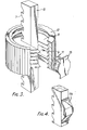
- Fig. 2 is a vertical section of the depth stop. Extending upwardly from the base plate 1 is a column 6 of rectangular transverse cross-section. One face of the column is formed as a rack with teeth 7 contoured as shown. The column 6 extends upwardly into a suitable recess in the housing 3.
- Movable along the length of the column 6 is a support member in the form of a collar 8 with a bore 9 of rectangular shape but whose dimensions are larger than those of the rack portion of the column by an extent sufficient to allow teeth 10 formed on a portion of the bore 9 to be engaged with and disengaged from the teeth 7. Disengagement is effected by moving the collar 8 to the left as seen in Fig. 2 against the action of a spring 11 acting between a face of the column and a plastics pad 15 which is pressed against a part of the bore 9. ,
- the collar 8 is of generally cylindrical shape, the curved outer surface being screw-threaded to receive a second collar 12 whose axial depth exceeds that of the collar 8.
- the base 13 of the scale 14 Resting upon the upper (as seen in Fig. 2) end of the collar 12 is the base 13 of the scale 14 that extends upwardly adjacent the column 6 from the base 13.
- the scale 14 carries markings indicating the extent by which the housing 3 can be moved towards the plate 1 before the upper surface of the base 13 comes into contact with the housing 3 and stops the movement.
- Adjustment of the depth stop is thus a two stage operation.
- the user sets the stop to approximately the correct position using the "coarse” adjustment provided by the toothed rack.
- the pad 15 acts to prevent vibration from the motor rotating the collar 12 away from the set position.
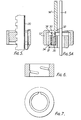
- Fig. 4 shows an alternative spring 11A which may be used in place of the spring 11 and pad 15 shown in Figs. 2 and 3.
- the scale rests on the top of the collar 12.
- Alternative arrangements would be to fix the scale to the collar 8 or to mount the scale in the collar 12 so that it moves vertically with the collar but does not rotate with it.
- An embodiment incorporating the latter arrangement is shown in Fig. 5.
- a single leaf spring 20 incorporating a scale is used in place of the spring 11, pad 15 and scale 14 shown in Figs. 2 and 3.
- Further alternative arrangements would be to Provide the scale in the form of a drum and fix the drum to the collar 12 or to omit the scale altogether.
- a scale 14' is provided with a flanged pedestal 30, semi-circular in plan, from which a lug 32 depends.
- a collar 12' is provided corresponding to the collar 12 described above but having an inwardly projecting circumferential flange 34 at its upper end to mate with the flanged periphery of the pedestal 30.
- a collar 8' is provided corresponding to the collar 8 described above but having a bore 34 therein in axial alignment with the lug 32.
- a helical compression spring 36 tapered at its upper end, is located in the bore 34 and about the lug 32. The action of the spring 36 is to retain the scale 14' from rotation with the outer collar 12' but to resiliently bias the pedestal against the flange 34 so that the scale moves vertically with the collar.
- the collar 12, instead of having a multi-turn thread as shown in Fig. 2 may have just a single turn as shown in Figs. 6 and 7 as this facilitates production of the collar.
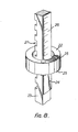
- FIG. B Another embodiment of the invention is illustrated in Fig. B.
- a single collar 22 is provided.
- a column 23 corresponds to the column 6 of Fig. 2 but the rack 27 formed on the column has a curved outer surface matching the bore of the collar 22 which has a deep screw thread and the teeth of the rack are inclined to match the pitch of the screw threaded bore.
- a leaf spring 24, which is held in fixed axial relationship with the collar 22 by torques 25 and has a scale 26 marked thereon is stressed between the adjacent surfaces of the collar and the rack and biases the collar 22 into threaded engagement with the rack.
- stop mechanism has been described in relation to a router, it will be appreciated that the mechanism could be used on many other tools, for example a drill stand, for height adjustment of a lawn mower/rake/brush, for positioning a rip fence on a band saw, bench saw, circular saw, as a depth stop on a circular saw or as a spreading control for a fertiliser spreader.
Abstract
A tool or machine in which the relative portion of two components is adjustable has setting means operable in a first mode to set the two components approximately to a desired setting and in a second mode to adjust the approximate setting accurately to a required setting. A tool for routing has a base plate (1) and a depth stop comprising a post (6) extending upwardly from the base plate, a first collar (8) movable along the post, a screw thread on the outer surface of the first collar, and a second collar (12) whose bore is screw-threaded screwed over the first collar. The post (6) includes a surface in the form of a toothed rack, the first collar has a bore one portion of whose surface is formed to engage one or more teeth (7) on the rack to lock the first collar (8) in a selected one of a number of predetermined positions along the post and a spring (11) resiliently biases the first collar into engagement with the toothed rack. A scale (14) operating with a fiducial mark is provided.
Description
- This invention relates to tools or machines where the relative position of two components is required to be set quickly and accurately, and in particular, but not exclusively, to tools for carrying out routing and like operations, for example, grooving, rebating and slotting.
- Such tools may comprise a base plate of generally annular form from which pillars extend. On the pillars is mounted a structure movable towards and away from the base plate. The structure includes a driving motor, usually an electric motor, on whose output shaft is mounted a collet for receiving a tool bit of a configuration appropriate to the task to be performed. On moving the structure towards the base plate, the tool bit moves through the central aperture in the base plate and into engagement with the work piece.
- The tool is fitted with a depth gauge that is set by a user and determines the extent of the downward movement of the structure. The extent of the downward movement of the structure determines the extent of movement of the bit and it is clearly important that the user be able to set the gauge accurately, easily and quickly.
- It is an object of the invention to provide a tool or machine in which the relative position of two components can be set quickly and accurately. A particular object of the invention is to provide a tool for carrying out routing and like operations including a depth stop which can be set quickly and accurately to a required setting.
- According to one aspect of the invention there is provided a tool or machine in which the relative position of two components is adjustable, the tool or machine including means for setting the relative position of the two components, the setting means being operable in a first mode to set the two components approximately to a desired setting and being operable in a second mode to adjust the approximate setting accurately to a required setting.
- According to another aspect of the invention there is provided a tool for carrying out routing and like operations, the tool including a depth stop having means for setting the stop, the setting means being operable in a first mode to set the two components approximately to a desired setting and being operable in a second mode to adjust the approximate setting accurately to a required setting.
- In one embodiment of the invention, the tool includes a base plate and a depth stop comprising a post extending upwardly from the base plate, a support member movable along the post, means for releasably locking the support member in a selected one of a number of predetermined positions along the post, and a location member so mounted upon the support member as to be capable of movement relatively thereto in a direction along the length of the Post.
- Preferably the post includes a surface, for example a surface in the form of a toothed rack, and the support member being resiliently biassed into engagement with the surface for retaining the support member in one of the predetermined positions. Where the surface is in the form of a toothed rack, the support member may be in the form of a collar having a bore one portion of whose surface is formed to engage one or more teeth on the rack to lock the collar in one of the predetermined positions. In this embodiment, the collar may be of generally cylindrical form, the curved surface of the collar being screw-threaded. A second collar whose bore is screw-threaded is screwed over the first mentioned collar.
- A scale which operates with a fiducial mark may be provided enabling a user to set the depth stop to a required position. Preferably, the scale is mounted so as to move vertically with the first-mentioned collar yet not to rotate with it.
- By way of example only, certain illustrative embodiments of the invention will now be described in greater detail with reference to the accompanying drawings of which :-
- Fig. 1 is a perspective view of the first embodiment,
- Fig. 2 is a vertical section of a part of the embodiment,
- Fig. 3 is a perspective partly exploded view of the embodiment of Fig. 2,
- Fig. 4 is a perspective view showing a modification to the embodiment of Figs. 2 and 3,
- Fig. 5 is a vertical section showing another modification to the embodiment of Figs. 2 and 3,
- Fig. 5A is a vertical section taken at right angles to the section of Fig. 5 and showing another modification to the embodiment of Figs. 2 and 3,
- Fig. 6 is a vertical section of one member which may be incorporated in the embodiments of the invention,
- Fig. 7 is a plan view of the member of Fig. 6, and
- Fig. 8 is a perspective view showing another embodiment of the invention.
- Referring first to Fig. 1, the tool shown is of the "plunge" type having a
base plate 1 of generally annular form. From the base, pillars 2 extend upwardly and carry ahousing 3 containing an electric drive motor, controls and safety switches therefor. On the output shaft of the motor is a collet 4 for receiving a tool bit. Extending sideways from thehousing 3 are handles 5 by means of which a user manipulates the tool. - The tool is used in conventional manner, the user first locates it in position and then by pressing down on the
handles 5 moves thehousing 3 towards thebase plate 1 and in so doing brings a bit in the chuck into engagement with a work piece (not shown). Springs 2a round the pillars 2 return the housing to its original position when the pressure is released. - The extent of the movement of the
housing 3 towards thebase plate 1 is preset by the user by means of adepth stop 6 andscale 14 fitted between the base plate and the housing. The depth stop will now be described with reference to Figs. 2 and 3. - Fig. 2 is a vertical section of the depth stop. Extending upwardly from the
base plate 1 is acolumn 6 of rectangular transverse cross-section. One face of the column is formed as a rack with teeth 7 contoured as shown. Thecolumn 6 extends upwardly into a suitable recess in thehousing 3. - Movable along the length of the
column 6 is a support member in the form of acollar 8 with abore 9 of rectangular shape but whose dimensions are larger than those of the rack portion of the column by an extent sufficient to allowteeth 10 formed on a portion of thebore 9 to be engaged with and disengaged from the teeth 7. Disengagement is effected by moving thecollar 8 to the left as seen in Fig. 2 against the action of a spring 11 acting between a face of the column and aplastics pad 15 which is pressed against a part of thebore 9. , - The
collar 8 is of generally cylindrical shape, the curved outer surface being screw-threaded to receive asecond collar 12 whose axial depth exceeds that of thecollar 8. - Resting upon the upper (as seen in Fig. 2) end of the
collar 12 is thebase 13 of thescale 14 that extends upwardly adjacent thecolumn 6 from thebase 13. Thescale 14 carries markings indicating the extent by which thehousing 3 can be moved towards theplate 1 before the upper surface of thebase 13 comes into contact with thehousing 3 and stops the movement. - Adjustment of the depth stop is thus a two stage operation. First, the user sets the stop to approximately the correct position using the "coarse" adjustment provided by the toothed rack. Second, by using the "fine" adjustment provided by the
second collar 12 an accurate positioning of the stop is obtained. - The user first shifts
collar 8 to the left as seen in Fig. 2 to disengage theteeth 10 on the collar to be disengaged from the teeth 7 of the rack and then, with the teeth held disengaged, the assembly comprising thecollars collar 12 relatively to thecollar 8, the former can be brought accurately into the required position. - The depth is now set and the tool ready for use.
- The
pad 15 acts to prevent vibration from the motor rotating thecollar 12 away from the set position. - Fig. 4 shows an
alternative spring 11A which may be used in place of the spring 11 andpad 15 shown in Figs. 2 and 3. - In the embodiment shown in Figs. 2 and 3, the scale rests on the top of the
collar 12. Alternative arrangements would be to fix the scale to thecollar 8 or to mount the scale in thecollar 12 so that it moves vertically with the collar but does not rotate with it. An embodiment incorporating the latter arrangement is shown in Fig. 5. Asingle leaf spring 20 incorporating a scale is used in place of the spring 11,pad 15 andscale 14 shown in Figs. 2 and 3. Further alternative arrangements would be to Provide the scale in the form of a drum and fix the drum to thecollar 12 or to omit the scale altogether. - Another arrangement in which the scale is mounted in the outer collar so that it moves vertically with the collar but does not rotate with it is shown in Fig: 5A. In the arrangement shown in Fig. 5A, a scale 14' is provided with a
flanged pedestal 30, semi-circular in plan, from which alug 32 depends. A collar 12' is provided corresponding to thecollar 12 described above but having an inwardly projectingcircumferential flange 34 at its upper end to mate with the flanged periphery of thepedestal 30. A collar 8' is provided corresponding to thecollar 8 described above but having abore 34 therein in axial alignment with thelug 32. Ahelical compression spring 36, tapered at its upper end, is located in thebore 34 and about thelug 32. The action of thespring 36 is to retain the scale 14' from rotation with the outer collar 12' but to resiliently bias the pedestal against theflange 34 so that the scale moves vertically with the collar. - The
collar 12, instead of having a multi-turn thread as shown in Fig. 2 may have just a single turn as shown in Figs. 6 and 7 as this facilitates production of the collar. - Another embodiment of the invention is illustrated in Fig. B. In this embodiment a
single collar 22 is provided. Acolumn 23 corresponds to thecolumn 6 of Fig. 2 but therack 27 formed on the column has a curved outer surface matching the bore of thecollar 22 which has a deep screw thread and the teeth of the rack are inclined to match the pitch of the screw threaded bore. Aleaf spring 24, which is held in fixed axial relationship with thecollar 22 bytorques 25 and has ascale 26 marked thereon is stressed between the adjacent surfaces of the collar and the rack and biases thecollar 22 into threaded engagement with the rack. - In order to set the depth stop of Fig. 2 the user pressed the
collar 22 against the bias of thespring 24 and slides the collar along the rack to approximately the correct position. Then, by rotating thecollar 22, but not thescale 26, an accurate positioning of the stop is obtained. - While the stop mechanism has been described in relation to a router, it will be appreciated that the mechanism could be used on many other tools, for example a drill stand, for height adjustment of a lawn mower/rake/brush, for positioning a rip fence on a band saw, bench saw, circular saw, as a depth stop on a circular saw or as a spreading control for a fertiliser spreader.
Claims (10)
1. A tool or machine in which the relative position of two components (3, 6) is adjustable, the tool or machine including means (8, 12) for setting the relative position of the two components, characterised in that the setting means (8, 12) are operable in a first mode to set the two components approximately to a desired setting and are operable in a second mode to adjust the approximate setting accurately to a required setting.
2. A tool as claimed in claim 1 further characterised in that the tool is a tool for carrying out routing and like operations and the two components are respectively a depth stop (6) and a component co-operating with the depth stop (3).
3. A tool as claimed in claim 2 further characterised in that the depth stop and setting means comprise a post (6), a support member (8) movable along the post, means (7, 10, 11) for releasably locking the support member in a selected'one of a number of predetermined positions along the post, and a location member (12) so mounted upon the support member (8) as to be capable of movement relatively thereto in a direction along the length of the post (6).
4. A tool as claimed in claim 3 further characterised in that the tool includes a base plate (1) and the post (6) extends upwardly from the base plate.
5. A tool as claimed in claim 3 or 4 further characterised in that the support member (8) is resiliently biassed into engagement with a surface of the post for retaining the support member in one of the predetermined positions.
6. A tool as claimed in claim 5 further characterised in that the surface is in the form of a toothed rack.
7. A tool as claimed in claim 6 further characterised in that the support member is in the form of a collar (8) having a bore (9) one portion (10) of whose surface is formed to engage one or more teeth (7) on the rack to lock the collar in one of the predetermined positions.
8. A tool as claimed in claim 7 further characterised in that the collar (8) is of generally cylindrical form, the curved surface of the collar is screw-threaded, and a second collar (12) constituting the location member and whose bore is screw-threaded is screwed over the first mentioned collar.
9. A tool as claimed in any preceding claim further characterised in that a scale (14) which operates with a fiducial mark is provided to enable a user to set the depth stop (6) to a required position.
10. A tool as claimed in claims 8 and 9 further characterised in that the scale (14) is mounted so as to move vertically with the first-mentioned collar (8) yet not to rotate with it.
Applications Claiming Priority (2)
| Application Number | Priority Date | Filing Date | Title |
|---|---|---|---|
| GB8037648 | 1980-11-24 | ||
| GB8037648 | 1980-11-24 |
Publications (2)
| Publication Number | Publication Date |
|---|---|
| EP0052994A2 true EP0052994A2 (en) | 1982-06-02 |
| EP0052994A3 EP0052994A3 (en) | 1983-08-17 |
Family
ID=10517523
Family Applications (1)
| Application Number | Title | Priority Date | Filing Date |
|---|---|---|---|
| EP81305421A Withdrawn EP0052994A3 (en) | 1980-11-24 | 1981-11-17 | Improvements in or relating to setting mechanisms especially for tools for carrying out routing and like operations |
Country Status (3)
| Country | Link |
|---|---|
| US (1) | US4445811A (en) |
| EP (1) | EP0052994A3 (en) |
| CA (1) | CA1170149A (en) |
Cited By (3)
| Publication number | Priority date | Publication date | Assignee | Title |
|---|---|---|---|---|
| JPS62173904U (en) * | 1986-04-25 | 1987-11-05 | ||
| JPH0269203A (en) * | 1988-09-02 | 1990-03-08 | Hitachi Koki Co Ltd | Regulating mechanism of depth of cut of portable electric router |
| GB2445257A (en) * | 2006-12-22 | 2008-07-02 | Bosch Gmbh Robert | Router with device for indicating position of housing |
Families Citing this family (48)
| Publication number | Priority date | Publication date | Assignee | Title |
|---|---|---|---|---|
| DE3314419C2 (en) * | 1983-04-21 | 1985-09-12 | Festo-Maschinenfabrik Gottlieb Stoll, 7300 Esslingen | Router with dust extraction |
| US4562872A (en) * | 1984-12-13 | 1986-01-07 | Makita Electric Works, Ltd. | Locking system in a portable electric router |
| US4770573A (en) * | 1986-10-15 | 1988-09-13 | Ryobi Ltd. | Cutting depth adjusting mechanism of a router |
| DE3824200C1 (en) * | 1988-07-16 | 1993-08-26 | Robert Bosch Gmbh, 7000 Stuttgart, De | |
| US4938642A (en) * | 1988-09-02 | 1990-07-03 | Hitachi Koki Company, Limited | Portable electric router |
| US5191921A (en) * | 1991-10-18 | 1993-03-09 | Ryobi Motor Products Corp. | Adjustable depth of cut stop mechanism for a plunge type router |
| DE4139759A1 (en) * | 1991-12-03 | 1993-06-09 | Robert Bosch Gmbh, 7000 Stuttgart, De | UP MILL |
| US5207253A (en) * | 1992-03-20 | 1993-05-04 | Ryobi Motor Products, Corp | Plunge router |
| US5310296A (en) * | 1993-05-18 | 1994-05-10 | Ryobi Motor Products | Plunge router with an elastically mounted bushing |
| US5577868A (en) * | 1995-06-29 | 1996-11-26 | Chen; Ruey Z. | Depth stop for a drill press |
| US5590989A (en) * | 1996-02-15 | 1997-01-07 | Mulvihill; Ralph | Flexible router height-adjustment mechanism |
| US5613813A (en) * | 1996-03-12 | 1997-03-25 | Ryobi North America, Inc. | Router adjustment ring |
| US5784789A (en) * | 1996-09-18 | 1998-07-28 | Vargas; Joseph J. | Rotary trim saw |
| US5967708A (en) * | 1998-03-12 | 1999-10-19 | Framatome Technologies, Inc. | Reactor vessel head tool positioning device |
| US5988241A (en) * | 1998-11-16 | 1999-11-23 | Porter-Cable Corporation | Ergonomic router handles |
| US6079915A (en) * | 1998-11-16 | 2000-06-27 | Porter-Cable Corporation | Plunge router depth stop system |
| US5998897A (en) * | 1998-11-16 | 1999-12-07 | Porter-Cable Corporation | Router chuck mounting system |
| US6139229A (en) * | 1998-11-16 | 2000-10-31 | Porter-Cable Corporation | Plunge router fine depth adjustment system |
| US6065912A (en) * | 1998-11-16 | 2000-05-23 | Porter-Cable Corporation | Router switching system |
| US6113323A (en) * | 1998-11-16 | 2000-09-05 | Porter-Cable Corporation | Plunge router sub-base alignment |
| US6261036B1 (en) | 1998-11-16 | 2001-07-17 | Porter-Cable Corporation | Plunge router locking system |
| US6488455B1 (en) | 2000-07-28 | 2002-12-03 | S-B Power Tool Company | Plunge base router |
| US8087437B2 (en) * | 2000-08-11 | 2012-01-03 | Techtronic Power Tools Technology Limited | Router |
| EP1238767B1 (en) * | 2000-08-11 | 2006-10-18 | Milwaukee Electric Tool Corporation | Router |
| US7451791B2 (en) * | 2002-10-15 | 2008-11-18 | Black & Decker Inc. | Handle assembly |
| US7316528B2 (en) * | 2002-10-15 | 2008-01-08 | Black & Decker Inc. | Ergonomic router assembly |
| US7073993B2 (en) * | 2002-10-15 | 2006-07-11 | Porter-Cable Corporation | Switch assembly |
| US7334614B2 (en) | 2002-10-15 | 2008-02-26 | Black & Decker Inc. | Depth adjustment mechanism |
| US7334613B2 (en) * | 2002-10-15 | 2008-02-26 | Black & Decker Inc. | Router base securing mechanism |
| US20060191597A1 (en) * | 2002-10-15 | 2006-08-31 | Black & Decker Inc. | Handle assembly |
| US6986369B1 (en) | 2002-11-12 | 2006-01-17 | Porter-Cable Corporation | Router height adjustment apparatus |
| US7089979B2 (en) | 2003-05-01 | 2006-08-15 | Black & Decker Inc. | Ergonomic router |
| US20060102249A1 (en) * | 2003-05-01 | 2006-05-18 | Cooper Randy G | Router with drive shaft lock mechanism |
| US7290575B2 (en) * | 2003-07-09 | 2007-11-06 | Credo Technology Corporation | Hybrid router |
| US7275900B1 (en) | 2003-07-25 | 2007-10-02 | Black & Decker Inc. | Router elevating mechanism |
| US7290574B2 (en) * | 2003-10-07 | 2007-11-06 | Credo Technology Corporation | Power tool support fixture |
| DE10359420A1 (en) * | 2003-12-18 | 2005-07-28 | Robert Bosch Gmbh | Hand tool |
| US7158852B2 (en) * | 2005-04-22 | 2007-01-02 | The Boeing Company | Methods for controlling dimensional variations in workpieces subjected to machining operations |
| GB0513856D0 (en) * | 2005-07-07 | 2005-08-10 | Black & Decker Inc | Router |
| US7448419B1 (en) * | 2005-09-16 | 2008-11-11 | Sommerfeld Marc S | Setup jig for a router bit |
| CN201009086Y (en) * | 2007-02-08 | 2008-01-23 | 南京德朔实业有限公司 | Power tool with adjustable height |
| WO2010094046A2 (en) | 2009-02-13 | 2010-08-19 | Black & Decker Inc. | Router |
| DE102011102066A1 (en) * | 2011-05-19 | 2012-11-22 | Festool Gmbh | Hand machine tool with a depth stop device |
| DE102011082263A1 (en) * | 2011-09-07 | 2013-03-07 | Robert Bosch Gmbh | Device for fine adjustment of portable machine tool e.g. router, has operation knob that is supported relative to housing unit, so that knob is movable along a direction different from direction of rotation axis of knob |
| US10556311B2 (en) * | 2017-04-04 | 2020-02-11 | Robert Bosch Gmbh | Lock device for power tool adjustment |
| US11648704B2 (en) | 2021-06-10 | 2023-05-16 | Black & Decker Inc. | Power tool router |
| USD975516S1 (en) | 2021-08-18 | 2023-01-17 | Woodpeckers, Llc | Drill guide |
| US11465217B1 (en) * | 2021-08-18 | 2022-10-11 | Woodpeckers, Llc | Method and apparatus for using a portable drill |
Citations (11)
| Publication number | Priority date | Publication date | Assignee | Title |
|---|---|---|---|---|
| DE361913C (en) * | 1922-10-20 | Burkhardt & Weber Maschinenfab | Adjustable stop for machine tools | |
| US1480522A (en) * | 1924-01-08 | Charles a | ||
| US1565790A (en) * | 1925-03-21 | 1925-12-15 | Ray L Carter | Portable routing machine |
| US2110537A (en) * | 1936-06-03 | 1938-03-08 | Delta Mfg Co | Drill press adjustment |
| US2318691A (en) * | 1942-03-02 | 1943-05-11 | Machinery Mfg Co | Micrometer stop |
| US2562143A (en) * | 1948-03-16 | 1951-07-24 | Stanley Works | Router |
| US2574653A (en) * | 1950-01-16 | 1951-11-13 | Clarence H Miller | Adjustable stop for power tools |
| US2664768A (en) * | 1950-06-01 | 1954-01-05 | Aloysius R Clyne | Motion limiting device |
| US3037405A (en) * | 1959-08-24 | 1962-06-05 | Francis W Zimmerman | Micrometer depth gage |
| US3689172A (en) * | 1970-11-25 | 1972-09-05 | William E Stites | Precision machine tool stop |
| US3791260A (en) * | 1972-02-17 | 1974-02-12 | Stanley Works | Router |
Family Cites Families (5)
| Publication number | Priority date | Publication date | Assignee | Title |
|---|---|---|---|---|
| DE14902C (en) * | A. KATH in Berlin | Button | ||
| US2736227A (en) * | 1956-02-28 | stroble | ||
| US1785395A (en) * | 1928-01-03 | 1930-12-16 | Keller Mechanical Eng | Zeroizing scale for work-positioning mechanism for machine tools |
| US2988119A (en) * | 1959-01-07 | 1961-06-13 | Stanley Works | Depth gage for a motor operated hand tool |
| US3037404A (en) * | 1960-07-01 | 1962-06-05 | Burgmaster Corp | Quick setting adjustable stop |
-
1981
- 1981-11-17 EP EP81305421A patent/EP0052994A3/en not_active Withdrawn
- 1981-11-19 US US06/322,946 patent/US4445811A/en not_active Expired - Lifetime
- 1981-11-20 CA CA000390504A patent/CA1170149A/en not_active Expired
Patent Citations (11)
| Publication number | Priority date | Publication date | Assignee | Title |
|---|---|---|---|---|
| DE361913C (en) * | 1922-10-20 | Burkhardt & Weber Maschinenfab | Adjustable stop for machine tools | |
| US1480522A (en) * | 1924-01-08 | Charles a | ||
| US1565790A (en) * | 1925-03-21 | 1925-12-15 | Ray L Carter | Portable routing machine |
| US2110537A (en) * | 1936-06-03 | 1938-03-08 | Delta Mfg Co | Drill press adjustment |
| US2318691A (en) * | 1942-03-02 | 1943-05-11 | Machinery Mfg Co | Micrometer stop |
| US2562143A (en) * | 1948-03-16 | 1951-07-24 | Stanley Works | Router |
| US2574653A (en) * | 1950-01-16 | 1951-11-13 | Clarence H Miller | Adjustable stop for power tools |
| US2664768A (en) * | 1950-06-01 | 1954-01-05 | Aloysius R Clyne | Motion limiting device |
| US3037405A (en) * | 1959-08-24 | 1962-06-05 | Francis W Zimmerman | Micrometer depth gage |
| US3689172A (en) * | 1970-11-25 | 1972-09-05 | William E Stites | Precision machine tool stop |
| US3791260A (en) * | 1972-02-17 | 1974-02-12 | Stanley Works | Router |
Cited By (4)
| Publication number | Priority date | Publication date | Assignee | Title |
|---|---|---|---|---|
| JPS62173904U (en) * | 1986-04-25 | 1987-11-05 | ||
| JPH0269203A (en) * | 1988-09-02 | 1990-03-08 | Hitachi Koki Co Ltd | Regulating mechanism of depth of cut of portable electric router |
| GB2445257A (en) * | 2006-12-22 | 2008-07-02 | Bosch Gmbh Robert | Router with device for indicating position of housing |
| GB2445257B (en) * | 2006-12-22 | 2009-08-26 | Bosch Gmbh Robert | Router |
Also Published As
| Publication number | Publication date |
|---|---|
| US4445811A (en) | 1984-05-01 |
| EP0052994A3 (en) | 1983-08-17 |
| CA1170149A (en) | 1984-07-03 |
Similar Documents
| Publication | Publication Date | Title |
|---|---|---|
| US4445811A (en) | Setting mechanisms especially for tools for carrying out routing and like operations | |
| US5998897A (en) | Router chuck mounting system | |
| US5483858A (en) | Sawing machine having angle-adjustable clamping mechanism and safety alignment mechanism | |
| CN1165064A (en) | Miter locking system for sliding compound miter saw | |
| US4537234A (en) | Routing machines | |
| CA1121696A (en) | Power tool apparatus and method | |
| US6079915A (en) | Plunge router depth stop system | |
| US5988241A (en) | Ergonomic router handles | |
| EP1987916B1 (en) | A grinding machine and a grinding jig therefore | |
| US6065912A (en) | Router switching system | |
| US6113323A (en) | Plunge router sub-base alignment | |
| US6182723B1 (en) | Switchable router brake system | |
| US6139229A (en) | Plunge router fine depth adjustment system | |
| US4335768A (en) | Depth of cut adjustment mechanism | |
| JPH0553564B2 (en) | ||
| US20040168555A1 (en) | Band saw | |
| EP0314029B1 (en) | Bench type milling cutter | |
| WO2004037487A1 (en) | Tool grinding machine | |
| US6948892B2 (en) | Lift mechanism for plunge routers | |
| JPS61244408A (en) | Sawing machine | |
| US2963060A (en) | Adjustable cutter head | |
| US2140322A (en) | Woodworking machine | |
| EP0042445A1 (en) | Depth of cut adjustment mechanism | |
| US6585017B1 (en) | Thickness planer with locking mechanism | |
| EP0394209B1 (en) | Improvement in and relating to grinding machines |
Legal Events
| Date | Code | Title | Description |
|---|---|---|---|
| PUAI | Public reference made under article 153(3) epc to a published international application that has entered the european phase |
Free format text: ORIGINAL CODE: 0009012 |
|
| AK | Designated contracting states |
Designated state(s): AT BE CH DE FR GB IT LU NL SE |
|
| PUAL | Search report despatched |
Free format text: ORIGINAL CODE: 0009013 |
|
| AK | Designated contracting states |
Designated state(s): AT BE CH DE FR GB IT LI LU NL SE |
|
| 17P | Request for examination filed |
Effective date: 19840208 |
|
| STAA | Information on the status of an ep patent application or granted ep patent |
Free format text: STATUS: THE APPLICATION IS DEEMED TO BE WITHDRAWN |
|
| 18D | Application deemed to be withdrawn |
Effective date: 19850417 |
|
| RIN1 | Information on inventor provided before grant (corrected) |
Inventor name: SANDERS, ANTHONY JONATHAN |