EP0052382B1 - Diffuser arrangements - Google Patents
Diffuser arrangements Download PDFInfo
- Publication number
- EP0052382B1 EP0052382B1 EP81110198A EP81110198A EP0052382B1 EP 0052382 B1 EP0052382 B1 EP 0052382B1 EP 81110198 A EP81110198 A EP 81110198A EP 81110198 A EP81110198 A EP 81110198A EP 0052382 B1 EP0052382 B1 EP 0052382B1
- Authority
- EP
- European Patent Office
- Prior art keywords
- screens
- vessel
- fluid
- pulp
- elongation
- Prior art date
- Legal status (The legal status is an assumption and is not a legal conclusion. Google has not performed a legal analysis and makes no representation as to the accuracy of the status listed.)
- Expired
Links
- 239000012530 fluid Substances 0.000 claims description 54
- 241000239290 Araneae Species 0.000 claims description 12
- 238000000034 method Methods 0.000 claims description 5
- 239000007788 liquid Substances 0.000 description 12
- 238000005406 washing Methods 0.000 description 11
- 230000037361 pathway Effects 0.000 description 5
- 230000008719 thickening Effects 0.000 description 5
- 238000010276 construction Methods 0.000 description 4
- 238000004061 bleaching Methods 0.000 description 3
- 230000009471 action Effects 0.000 description 2
- 238000009792 diffusion process Methods 0.000 description 2
- 239000000463 material Substances 0.000 description 2
- 230000007246 mechanism Effects 0.000 description 2
- 238000012856 packing Methods 0.000 description 2
- 238000009827 uniform distribution Methods 0.000 description 2
- 238000005273 aeration Methods 0.000 description 1
- 230000000712 assembly Effects 0.000 description 1
- 238000000429 assembly Methods 0.000 description 1
- 238000005452 bending Methods 0.000 description 1
- 230000029087 digestion Effects 0.000 description 1
- 230000000694 effects Effects 0.000 description 1
- 238000000605 extraction Methods 0.000 description 1
- 239000006260 foam Substances 0.000 description 1
- 238000007689 inspection Methods 0.000 description 1
- 238000012423 maintenance Methods 0.000 description 1
- 230000002028 premature Effects 0.000 description 1
- 238000004064 recycling Methods 0.000 description 1
- 238000007789 sealing Methods 0.000 description 1
- 230000035939 shock Effects 0.000 description 1
- 239000007787 solid Substances 0.000 description 1
- 238000000638 solvent extraction Methods 0.000 description 1
- 230000003068 static effect Effects 0.000 description 1
- XLYOFNOQVPJJNP-UHFFFAOYSA-N water Substances O XLYOFNOQVPJJNP-UHFFFAOYSA-N 0.000 description 1
Images


Classifications
-
- D—TEXTILES; PAPER
- D21—PAPER-MAKING; PRODUCTION OF CELLULOSE
- D21C—PRODUCTION OF CELLULOSE BY REMOVING NON-CELLULOSE SUBSTANCES FROM CELLULOSE-CONTAINING MATERIALS; REGENERATION OF PULPING LIQUORS; APPARATUS THEREFOR
- D21C9/00—After-treatment of cellulose pulp, e.g. of wood pulp, or cotton linters ; Treatment of dilute or dewatered pulp or process improvement taking place after obtaining the raw cellulosic material and not provided for elsewhere
- D21C9/02—Washing ; Displacing cooking or pulp-treating liquors contained in the pulp by fluids, e.g. wash water or other pulp-treating agents
Definitions
- Continuous diffuser washers have been extremely successful in simplifying pulp washing operations, especially immediately after continuous digestion of the pulp.
- Conventional diffuser washers are usually mounted on the brown stock storage tank and effect washing in a closed system where no air comes in contact with the pulp, reducing the tendency to foam, facilitating pollution abatement, and permitting greater recycling and reuse of liquors.
- the pulp is passed upwardly in the diffuser vessel and passes between a plurality of concentric withdrawal screen rings, washing liquid being introduced through tubes that are rotating within the areas defined by the screen rings and being attached to a scraper at the top of the vessel.
- the screens are moved up and down by hydraulic cylinders mounted outside the vessel walls, suitable mechanical interconnections extending through the vessel walls from the cylinders to the screens, and also providing for withdrawal of liquid from the screens through the vessel walls.
- Such a reciprocating screen arrangement is also useful for thickenening of pulp either in a separate thickening vessel or as part of the diffusion washing sequence.
- Exemplary prior art diffuser washers and/or thickners are shown in U.S. Patent Nos. 3,348,390; 3,372,087; 3,575,795; 4,076,623; and 4,100,069.
- an upright hollow vessel containing a plurality of withdrawal screens extending substantially parallel to the vessel direction of elongation, conduit means for supporting the withdrawal screens and for providing passage of fluid from the withdrawal screens to an area remote from the withdrawal screens, and means for reciprocating the conduit means with attached withdrawal screens up and down in a direction substantially coincident with the direction of elongation of the vessel.
- Fluid introducing structures are provided supported by said conduit means, the conduit means providing for passage of fluid from an area remote from the fluid introducing structures to the fluid introducing structures.
- the withdrawal screens and fluid introducing structures are interspersed with each other and are stationary with respect to each other. This arrangement allows the construction of the withdrawal screens and fluid introducing structures in a wide variety of manners.
- the screens and structures can be disposed in concentric quadrates (when viewed along the vessel direction of elongation), or in parallel straight lines. All of the screens and fluid introducing structures when in a given vessel can thus be constructed in the same manner, and the withdrawal screens and fluid introducing structures can be made interchangeable with each other.
- the fluid introducing structures are preferably formed as a plurality of plates having openings formed therein that are larger and more widely spaced than openings provided in the withdrawal screens, the openings being prismoid in configuration and having a larger cross-sectional area closer to the fluid introducing structure end than the center.
- the method according to the present invention is applicable to the washing and/or thickening of cellulosic pulp material having a consistency of about 6-15% (8-12% being the approximate maximum efficiency range), and may be practiced in a simple and efficient manner.
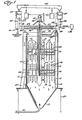
- the basic apparatus includes an elongated upright hollow vessel 10 (including side 11 and bottom 13 walls, and an open top 15), a plurality of withdrawal screens 12, and a plurality of fluid introducing structures 14, a conduit or conduit means 16, and apparatus or means 18 for reciprocating the conduit means back and forth in the direction A-A of elongation of the vessel 10.
- the vessel 10 would normally be mounted on a brown stock storage tank 20, with an inlet 21 being provided from the washing stage of a continuous digester, and with an outlet 22 being provided from the vessel 10 to the brown stock washer 20.
- the apparatus according to the invention is not restricted to such an environment, and can be utilized in any place where washing, bleaching, and/or thickening is desired, with suitable interconnections to associated structures being provided.
- the withdrawal screens 12 extend substantially parallel to the direction A-A and are spaced from each other in one or more directions perpendicular to the vessel direction of elongation.
- the fluid introducing structures 14 may comprise spaced tubular members, but preferably are provided by plates 49 (see Figures 1-4 in particular), the plates having openings 51 (see FIG. 8) formed therein that are larger and more widely spaced than the openings provided in the screens 12.
- the total area of the openings provided in the fluid introducing means 14 as compared to the screens 12 may be approximately one-tenth or less, in order to create the pressure differential desired for uniform distribution. If desired portions of the structures 14 connected to the conduit means 16 may be solid (as shown in Figure 1), the openings not being provided until positions more remote from the conduit means 16.
- the conduit means 16 preferably take the form of a plurality of spider arms 24 which extend radially outwardly from a central tubular portion 25 extending in the direction of elongation A-A of the vessel 10. Flexible withdrawal and inlet conduits 26, 27 respectively are operatively connected to the central portion 25 as illustrated in Figure 1.
- the conduit means 16 support the screens 12 and structures 14 so that they are interspersed with each other and stationary with respect to each other, and provide for passage of fluid from an area remote from the structures 14 to the structures 14, and for passage of fluid from the screens 12 to an area remote from the screens 12.
- each spider arm 24 arrangement includes one set of screens 12 and structures 14 extending upwardly therefrom, and another set extending downwardly therefrom.
- the upper spider arm 24 assembly includes one set of screens 12 extending downwardly therefrom, and the bottom spider arm 24 assembly includes one set of screens 12 extending upwardly therefrom with interspersed fluid introducing structures 14.
- the screens 12 and fluid introducing structures 14 may take a wide variety of configurations.
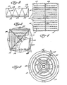
- the screens 12 and structures 14 are disposed in concentric quadrates when viewed along the vessel direction of elongation A-A, with the spider arms 24 interconnecting the corners of the quadrates.
- the screens 12 and structures 14 are shown disposed in concentric circles, and in Figures 1, and 4-6 the screens 12 and s t ruc- tures 14 are shown disposed in parallel straight lines when viewed along the direction A-A, with the conduit means arms 24 extending perpendicularly to the straight lines.
- FIG. 1 An exemplary manner in which the conduit means 16 may provide for the introduction to and withdrawal of fluid from the vessel 10 is illustrated in Figure 1.
- Withdrawal for the lower spider arm 24 assembly is provided through a first passage, indicated by arrows 33
- withdrawal from the top spider arm 24 assembly is provided by another passageway indicated by arrows 34
- fluid introduction to the structures 14 of the top spider arm assembly 24 is provided through a passageway indicated by arrows 35
- fluid for the lower spider arm assembly 24 is introduced by a passageway indicated by arrows 36.
- the fluid introduced into pathway 35 is preferably wash liquid from a source 136 or the like.
- Liquid withdrawn from the screens 12 connected to pathway 34 passes to a tank 37 through a flow controlled valve arrangement 38, and that liquid can be used as the wash water for pathway 36, the flow from the tank 37 into pathway 36 being controlled by a level-controlled valve assembly 39.
- Liquid withdrawn through the screens 12 connected to the pathway 33 passes through flow control valve assembly 43 to tank 40, and that liquid may in turn pass level-responsive valve assembly 41 through line 42 to be used as wash liquid in the bottom of the continuous digester to which the vessel 10 is connected.
- a de-aeration system 44 also is provided, which facilitates the creation of static backwash when the extraction valve assemblies 38, 43 are closed.
- an appropriate pressure differential for uniform distribution may be provided by splitting the flow of the liquid being introduced so that it is one-half of the suction.
- two pipes may be separately run into the spider arms, and a valve timed to switch between the pipes at predetermined intervals (e.g. 10 seconds).
- the openings in the fluid introducing structures which are larger and more widely spaced than the openings provided in the withdrawal screens 12, may be prismoid in configuration, as illustrated in Figure 8.
- a section of fluid introducing structure 14 is illustrated having a central portion 50 thereof through which liquid to be introduced flows, a plurality of openings 51 being provided are operatively connected through orifices 52 to the structure 50.
- the openings 51 have slanted walls 53 in both dimensions so that they take a prismoid configuration, having a small cross-sectional area at the center of the structure 14 (adjacent opening 52) and having a larger cross-sectional area at the end thereof. Such an arrangement is more fully described in U.S. Patent No. 3,913,838 (the disclosure of which is hereby incorporated by reference herein), and ensures that clogging of the openings 51 will be avoided.
- the openings 51 may be oriented so that they introduce the liquid vertically or horizontally.
- the reciprocating means 18 preferably consists of a single linear actuator 60, which is preferably mounted above the vessel 10 and within the cross-sectional area thereof.
- the actuator 60 moves the conduit means 16 with attached screens 12 and structures 14 upwardly at a first rate a predetermined distance, and then downwardly at a second rate the predetermined distance, the second rate being much greater than the first rate and great enough to facilitate dislodgement of materials clinging to the screen faces when in use for treating pulp.
- the linear actuator 60 preferably may comprise a hydraulic cylinder.
- a reciprocating mechanism such as employed in U.S. Patent No. 4,076,623 may be employed when a different reciprocating action is desired.
- a plurality of withdrawal conduits 62 are provided around the periphery of the vessel 10 at the top thereof.
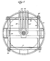
- the means for distributing pulp from the interior of the vessel at the top thereof into the conduit 62 comprise a plurality of distinct wiper blades 64 (only one of which is shown in Figures 1-3) and means for oscillating the wiper blades 64 about axis parallel to the direction of elongation A-A of the vessel 10.
- Exemplary oscillating means are illustrated most clearly in Figures 5-7, and may comprise a single linear actuator (such as a hydraulic cylinder) 66 (see Figure 7) mounted above the vessel 10 and within the cross-sectional area thereof.
- Each wiper blade 64 is connected to a plate 68, which in turn is pivotally connected to a pair of levers, such as levers 69, 70 (see Figure 7) the levers 69, 70, and 71 - together with the levers 72, 73 which are connected to the linear actuator 66 - forming the sides of a polygon, and operating the wipers 64 so that they do not interfere with each other but so that they move the pulp from the interior of the vessel toward the conduit 62.
- the vessel 10 may be quadrate in cross section with withdrawal conduits 62 provided along each side thereof and a wiper blade 64 mounted at each corner of the vessel at the top thereof, with each wiper blade having an effective length of slightly more than one-half the length of the vessel sides merging to form the corner at which the blade 64 is disposed.
- the apparatus according to the present invention is most useful for treating pulp having a consistency of about 6-1 5%, and can be utilized for bleaching, washing, and/or thickening of the pulp.
- the pulp is passed from a continuous digester through conduit 21 to the vessel 10, flowing upwardly in the vessel 10. As it flows upwardly between the screens 12 and fluid introducing structures 14, it is acted upon by the fluid being introduced, and liquid is withdrawn therefrom and passed to a point exterior of the vessel 10.
- Pulp is withdrawn from the top of the vessel 10 by oscillating the wiper blades 64 to move the pulp into the conduits 62, which conduits 62 lead to an outlet 22 which conveys the pulp to a brown stock storage tank 20, or like structure (depending upon the treatment being provided for the pulp in the vessel 10).
- the screens 12 and structures 14 - which remain stationary with respect to each other - are reciprocated upwardly and downwardly in the vessel along the vessel direction of elongation A-A.
- the screens 12 and structures 14 are moved upwardly at a first relatively slow rate, approximately matching the upflow rate of the pulp in the vessel 10, and then the screens 12 and structures 14 are moved downwardly at a second rate much greater than the first rate, and great enough to facilitate dislodgement of pulp clinging to the faces of the screens 12.
Landscapes
- Life Sciences & Earth Sciences (AREA)
- Engineering & Computer Science (AREA)
- Wood Science & Technology (AREA)
- Paper (AREA)
Description
- Continuous diffuser washers have been extremely successful in simplifying pulp washing operations, especially immediately after continuous digestion of the pulp. Conventional diffuser washers are usually mounted on the brown stock storage tank and effect washing in a closed system where no air comes in contact with the pulp, reducing the tendency to foam, facilitating pollution abatement, and permitting greater recycling and reuse of liquors. The pulp is passed upwardly in the diffuser vessel and passes between a plurality of concentric withdrawal screen rings, washing liquid being introduced through tubes that are rotating within the areas defined by the screen rings and being attached to a scraper at the top of the vessel. The screens are moved up and down by hydraulic cylinders mounted outside the vessel walls, suitable mechanical interconnections extending through the vessel walls from the cylinders to the screens, and also providing for withdrawal of liquid from the screens through the vessel walls. Such a reciprocating screen arrangement is also useful for thickenening of pulp either in a separate thickening vessel or as part of the diffusion washing sequence. Exemplary prior art diffuser washers and/or thickners are shown in U.S. Patent Nos. 3,348,390; 3,372,087; 3,575,795; 4,076,623; and 4,100,069.
- While conventional continuous washers are successful in performing their intended functions, and provide the most efficient commercially available washing to date, there have been a number of practical problems associated therewith. For instance, because of the ring-like construction, the components are expensive to fabricate, and each screen ring and liquid-introducing nozzle within a given structure must be constructed differently in order to provide varying flow rates to accomplish uniform washing. The ring construction also means that significant bending and twisting stresses are applied to the structure as it is reciprocated up and down, especially providing stress at the connections of the arms to the rings and sometimes resulting in premature failure of the assembly. The relative movement between the diffuser tubes and the screens causes a shock wave in the area between the tubes and screens. The structures for packing the central rotor, and for packing and sealing the arms where they extend through the vessel side walls to the cylinders, are expensive and require considerable maintenance if leakage is to be prevented. Also, rotation of the central rotor results in significant energy usage.
- According to the present invention, any problems inherent in prior art continuous diffuser washers are eliminated by providing a greatly simplified structure.
- According to the present invention, an upright hollow vessel is provided containing a plurality of withdrawal screens extending substantially parallel to the vessel direction of elongation, conduit means for supporting the withdrawal screens and for providing passage of fluid from the withdrawal screens to an area remote from the withdrawal screens, and means for reciprocating the conduit means with attached withdrawal screens up and down in a direction substantially coincident with the direction of elongation of the vessel. Fluid introducing structures are provided supported by said conduit means, the conduit means providing for passage of fluid from an area remote from the fluid introducing structures to the fluid introducing structures. The withdrawal screens and fluid introducing structures are interspersed with each other and are stationary with respect to each other. This arrangement allows the construction of the withdrawal screens and fluid introducing structures in a wide variety of manners. For instance, instead of being provided as rings, the screens and structures can be disposed in concentric quadrates (when viewed along the vessel direction of elongation), or in parallel straight lines. All of the screens and fluid introducing structures when in a given vessel can thus be constructed in the same manner, and the withdrawal screens and fluid introducing structures can be made interchangeable with each other. The fluid introducing structures are preferably formed as a plurality of plates having openings formed therein that are larger and more widely spaced than openings provided in the withdrawal screens, the openings being prismoid in configuration and having a larger cross-sectional area closer to the fluid introducing structure end than the center.
- The method according to the present invention is applicable to the washing and/or thickening of cellulosic pulp material having a consistency of about 6-15% (8-12% being the approximate maximum efficiency range), and may be practiced in a simple and efficient manner.
- It is the primary object of the present invention to provide an improved apparatus and method especially adapted for washing, bleaching, and/or thickening of pulp. This and other objects of the invention will become clear from an inspection of the detailed description of the invention, and from the appended claims.
-
- FIGURE 1 is a cross-sectional schematic view of exemplary apparatus according to the present invention;
- FIGURES 2-4 are top schematic views of exemplary withdrawal screen and fluid introducing structure configurations that may be provided according to the invention;
- FIGURE 5 is a side cross-sectional view of another exemplary form of apparatus according to the invention, taken along lines 5-5 of FIGURE 6;
- FIGURE 6 is a cross-sectional view taken along lines 6-6 of Figure 5;
- FIGURE 7 is a top plan view of the embodiment of Figures 5 and 6; and
- FIGURE 8 is a detailed view of an exemplary form of construction of the fluid introducing structure openings that may be utilized in practicing the invention.
- The basic apparatus according to the present invention includes an elongated upright hollow vessel 10 (including side 11 and
bottom 13 walls, and an open top 15), a plurality ofwithdrawal screens 12, and a plurality offluid introducing structures 14, a conduit or conduit means 16, and apparatus or means 18 for reciprocating the conduit means back and forth in the direction A-A of elongation of the vessel 10. The vessel 10 would normally be mounted on a brownstock storage tank 20, with an inlet 21 being provided from the washing stage of a continuous digester, and with an outlet 22 being provided from the vessel 10 to thebrown stock washer 20. However, the apparatus according to the invention is not restricted to such an environment, and can be utilized in any place where washing, bleaching, and/or thickening is desired, with suitable interconnections to associated structures being provided. - The
withdrawal screens 12 extend substantially parallel to the direction A-A and are spaced from each other in one or more directions perpendicular to the vessel direction of elongation. Thefluid introducing structures 14 may comprise spaced tubular members, but preferably are provided by plates 49 (see Figures 1-4 in particular), the plates having openings 51 (see FIG. 8) formed therein that are larger and more widely spaced than the openings provided in thescreens 12. The total area of the openings provided in thefluid introducing means 14 as compared to thescreens 12 may be approximately one-tenth or less, in order to create the pressure differential desired for uniform distribution. If desired portions of thestructures 14 connected to the conduit means 16 may be solid (as shown in Figure 1), the openings not being provided until positions more remote from the conduit means 16. - The conduit means 16 preferably take the form of a plurality of
spider arms 24 which extend radially outwardly from a centraltubular portion 25 extending in the direction of elongation A-A of the vessel 10. Flexible withdrawal andinlet conduits central portion 25 as illustrated in Figure 1. The conduit means 16 support thescreens 12 andstructures 14 so that they are interspersed with each other and stationary with respect to each other, and provide for passage of fluid from an area remote from thestructures 14 to thestructures 14, and for passage of fluid from thescreens 12 to an area remote from thescreens 12. - In many situations, more than one set of
screens 12 and/orstructures 14 will be provided, and in such a situation interior partitioning means 30 will be provided in thearms 24 andcentral portion 25 to provide for separate introduction and withdrawal of fluids. Any number ofspider arms 24 arrangement, with associatedscreens 12 andfluid introducing structures 14, may be provided in the vessel 10, two such arrangements being illustrated in the Figure 1 and Figure 5 embodiments. - In the Figure 1 embodiment, each
spider arm 24 arrangement includes one set ofscreens 12 andstructures 14 extending upwardly therefrom, and another set extending downwardly therefrom. In the Figure 5 embodiment, theupper spider arm 24 assembly includes one set ofscreens 12 extending downwardly therefrom, and thebottom spider arm 24 assembly includes one set ofscreens 12 extending upwardly therefrom with interspersedfluid introducing structures 14. - The
screens 12 andfluid introducing structures 14 may take a wide variety of configurations. For instance, in Figure 2 thescreens 12 andstructures 14 are disposed in concentric quadrates when viewed along the vessel direction of elongation A-A, with thespider arms 24 interconnecting the corners of the quadrates. In Figure 3, thescreens 12 andstructures 14 are shown disposed in concentric circles, and in Figures 1, and 4-6 thescreens 12 and struc-tures 14 are shown disposed in parallel straight lines when viewed along the direction A-A, with the conduit meansarms 24 extending perpendicularly to the straight lines. In the embodiments of Figures 2 and 4, less stress will be placed on the interconnections between the arms and thescreens 12 than when a ring configuration is provided, and thescreens 12 andstructures 14 can be welded directly to thearms 24. In the Figures 1 and 4-6 embodiment, all of thescreens 12, and all of thedistributing structures 14, can be made in the same manner, and connections 32 (see Figure 5) may be provided at thearms 24 that allow interconnection of eitherscreens 12 orfluid distributing devices 14 thereat. - An exemplary manner in which the conduit means 16 may provide for the introduction to and withdrawal of fluid from the vessel 10 is illustrated in Figure 1. Withdrawal for the
lower spider arm 24 assembly is provided through a first passage, indicated by arrows 33, withdrawal from thetop spider arm 24 assembly is provided by another passageway indicated by arrows 34, fluid introduction to thestructures 14 of the topspider arm assembly 24 is provided through a passageway indicated by arrows 35, and fluid for the lowerspider arm assembly 24 is introduced by a passageway indicated by arrows 36. The fluid introduced into pathway 35 is preferably wash liquid from a source 136 or the like. Liquid withdrawn from thescreens 12 connected to pathway 34 passes to atank 37 through a flow controlled valve arrangement 38, and that liquid can be used as the wash water for pathway 36, the flow from thetank 37 into pathway 36 being controlled by a level-controlled valve assembly 39. Liquid withdrawn through thescreens 12 connected to the pathway 33 passes through flow control valve assembly 43 to tank 40, and that liquid may in turn pass level-responsive valve assembly 41 through line 42 to be used as wash liquid in the bottom of the continuous digester to which the vessel 10 is connected. Ade-aeration system 44 also is provided, which facilitates the creation of static backwash when the extraction valve assemblies 38, 43 are closed. - If desired, an appropriate pressure differential for uniform distribution may be provided by splitting the flow of the liquid being introduced so that it is one-half of the suction. In such a situation two pipes may be separately run into the spider arms, and a valve timed to switch between the pipes at predetermined intervals (e.g. 10 seconds). The openings in the fluid introducing structures, which are larger and more widely spaced than the openings provided in the
withdrawal screens 12, may be prismoid in configuration, as illustrated in Figure 8. In Figure 8, a section offluid introducing structure 14 is illustrated having a central portion 50 thereof through which liquid to be introduced flows, a plurality of openings 51 being provided are operatively connected throughorifices 52 to the structure 50. The openings 51 have slanted walls 53 in both dimensions so that they take a prismoid configuration, having a small cross-sectional area at the center of the structure 14 (adjacent opening 52) and having a larger cross-sectional area at the end thereof. Such an arrangement is more fully described in U.S. Patent No. 3,913,838 (the disclosure of which is hereby incorporated by reference herein), and ensures that clogging of the openings 51 will be avoided. The openings 51 may be oriented so that they introduce the liquid vertically or horizontally. - The reciprocating means 18 preferably consists of a single linear actuator 60, which is preferably mounted above the vessel 10 and within the cross-sectional area thereof. The actuator 60 moves the conduit means 16 with attached
screens 12 andstructures 14 upwardly at a first rate a predetermined distance, and then downwardly at a second rate the predetermined distance, the second rate being much greater than the first rate and great enough to facilitate dislodgement of materials clinging to the screen faces when in use for treating pulp. Such an action is more fully described in U.S. Patent No. 3,372,087. Normally, the upward velocity of the pulp is matched by thescreens 12 during the upward movement. If operation in this manner is desired the linear actuator 60 preferably may comprise a hydraulic cylinder. Alternatively, a reciprocating mechanism such as employed in U.S. Patent No. 4,076,623 may be employed when a different reciprocating action is desired. - In normal use of the vessel 10, pulp will flow upwardly therein, and a mechanism must be provided at the top of the vessel 10 for withdrawal of the treated pulp. A plurality of withdrawal conduits 62 (see Figures 1, 2, and 3 in particular) are provided around the periphery of the vessel 10 at the top thereof. The means for distributing pulp from the interior of the vessel at the top thereof into the
conduit 62 comprise a plurality of distinct wiper blades 64 (only one of which is shown in Figures 1-3) and means for oscillating thewiper blades 64 about axis parallel to the direction of elongation A-A of the vessel 10. Exemplary oscillating means are illustrated most clearly in Figures 5-7, and may comprise a single linear actuator (such as a hydraulic cylinder) 66 (see Figure 7) mounted above the vessel 10 and within the cross-sectional area thereof. Eachwiper blade 64 is connected to aplate 68, which in turn is pivotally connected to a pair of levers, such as levers 69, 70 (see Figure 7) thelevers 69, 70, and 71 - together with thelevers 72, 73 which are connected to the linear actuator 66 - forming the sides of a polygon, and operating thewipers 64 so that they do not interfere with each other but so that they move the pulp from the interior of the vessel toward theconduit 62. As shown in Figure 2, the vessel 10 may be quadrate in cross section withwithdrawal conduits 62 provided along each side thereof and awiper blade 64 mounted at each corner of the vessel at the top thereof, with each wiper blade having an effective length of slightly more than one-half the length of the vessel sides merging to form the corner at which theblade 64 is disposed. - The apparatus according to the present invention is most useful for treating pulp having a consistency of about 6-1 5%, and can be utilized for bleaching, washing, and/or thickening of the pulp. In an exemplary manner of treating pulp according to the present invention, the pulp is passed from a continuous digester through conduit 21 to the vessel 10, flowing upwardly in the vessel 10. As it flows upwardly between the
screens 12 andfluid introducing structures 14, it is acted upon by the fluid being introduced, and liquid is withdrawn therefrom and passed to a point exterior of the vessel 10. Pulp is withdrawn from the top of the vessel 10 by oscillating thewiper blades 64 to move the pulp into theconduits 62, whichconduits 62 lead to an outlet 22 which conveys the pulp to a brownstock storage tank 20, or like structure (depending upon the treatment being provided for the pulp in the vessel 10). As the pulp is passed upwardly in the vessel 10, thescreens 12 and structures 14 - which remain stationary with respect to each other - are reciprocated upwardly and downwardly in the vessel along the vessel direction of elongation A-A. Preferably, thescreens 12 andstructures 14 are moved upwardly at a first relatively slow rate, approximately matching the upflow rate of the pulp in the vessel 10, and then thescreens 12 andstructures 14 are moved downwardly at a second rate much greater than the first rate, and great enough to facilitate dislodgement of pulp clinging to the faces of thescreens 12. - It will thus be seen that according to the present invention a simple structure has been provided which eliminates most of the problems associated with prior art diffusion washers and the like.
Claims (7)
Priority Applications (1)
| Application Number | Priority Date | Filing Date | Title |
|---|---|---|---|
| DE8080102108T DE3061861D1 (en) | 1979-04-25 | 1980-04-18 | Apparatus for continuous treatment of pulp |
Applications Claiming Priority (2)
| Application Number | Priority Date | Filing Date | Title |
|---|---|---|---|
| US34928 | 1979-04-25 | ||
| US06/034,928 US4276167A (en) | 1979-04-25 | 1979-04-25 | Diffuser arrangements |
Related Parent Applications (2)
| Application Number | Title | Priority Date | Filing Date |
|---|---|---|---|
| EP80102108A Division EP0018562B1 (en) | 1979-04-25 | 1980-04-18 | Apparatus for continuous treatment of pulp |
| EP80102108A Division-Into EP0018562B1 (en) | 1979-04-25 | 1980-04-18 | Apparatus for continuous treatment of pulp |
Publications (2)
| Publication Number | Publication Date |
|---|---|
| EP0052382A1 EP0052382A1 (en) | 1982-05-26 |
| EP0052382B1 true EP0052382B1 (en) | 1984-10-17 |
Family
ID=21879519
Family Applications (3)
| Application Number | Title | Priority Date | Filing Date |
|---|---|---|---|
| EP80102108A Expired EP0018562B1 (en) | 1979-04-25 | 1980-04-18 | Apparatus for continuous treatment of pulp |
| EP81110199A Expired EP0056859B1 (en) | 1979-04-25 | 1980-04-18 | Diffuser arrangements |
| EP81110198A Expired EP0052382B1 (en) | 1979-04-25 | 1980-04-18 | Diffuser arrangements |
Family Applications Before (2)
| Application Number | Title | Priority Date | Filing Date |
|---|---|---|---|
| EP80102108A Expired EP0018562B1 (en) | 1979-04-25 | 1980-04-18 | Apparatus for continuous treatment of pulp |
| EP81110199A Expired EP0056859B1 (en) | 1979-04-25 | 1980-04-18 | Diffuser arrangements |
Country Status (6)
| Country | Link |
|---|---|
| US (1) | US4276167A (en) |
| EP (3) | EP0018562B1 (en) |
| JP (1) | JPS55142786A (en) |
| BR (1) | BR8002567A (en) |
| CA (1) | CA1121638A (en) |
| FI (1) | FI68096C (en) |
Families Citing this family (7)
| Publication number | Priority date | Publication date | Assignee | Title |
|---|---|---|---|---|
| US4468319A (en) * | 1982-05-04 | 1984-08-28 | Laakso Oliver A | Stationary diffuser |
| US4394267A (en) * | 1982-07-12 | 1983-07-19 | Kamyr, Inc. | Diffuser assembly |
| SE452343B (en) * | 1984-02-22 | 1987-11-23 | Billeruds Ab | SET AND EQUIPMENT FOR CONTINUOUS CELLULOS COOKING |
| US5788812A (en) * | 1985-11-05 | 1998-08-04 | Agar; Richard C. | Method of recovering furfural from organic pulping liquor |
| SE503071C2 (en) * | 1994-07-04 | 1996-03-18 | Kvaerner Pulping Tech | Continuous pulp wash diffuser including annular hydraulic cylinders |
| US6272710B1 (en) | 1998-05-07 | 2001-08-14 | James R. Prough | Plate diffuser for treating comminuted cellulosic fibrous material |
| US8747613B2 (en) * | 2009-08-25 | 2014-06-10 | Valmet Ab | Pressure diffuser with less power rating in hydraulic system |
Family Cites Families (7)
| Publication number | Priority date | Publication date | Assignee | Title |
|---|---|---|---|---|
| SE198496C1 (en) * | 1963-05-20 | 1965-09-21 | ||
| SE306876B (en) * | 1967-05-05 | 1968-12-09 | Kamyr Ab | |
| CA834629A (en) * | 1966-09-30 | 1970-02-17 | Amiel W. Brinkley, Jr. | Rapid high consistency bleaching of pulp |
| US3524551A (en) * | 1967-02-14 | 1970-08-18 | Kamyr Ab | Apparatus for concentrating and/or washing cellulosic pulp |
| FR2019454A6 (en) * | 1968-09-18 | 1970-07-03 | Sunds Ab | |
| SE369322B (en) * | 1973-08-30 | 1974-08-19 | Kamyr Ab | |
| SE386692B (en) * | 1974-03-14 | 1976-08-16 | Sunds Ab | CONCENTRATION AND / OR LIQUID TREATMENT DEVICE AS WASHING OR BLEACHING OF LIQUID SUBSTANCES, SPECIAL CELLULOSE PULP |
-
1979
- 1979-04-25 US US06/034,928 patent/US4276167A/en not_active Expired - Lifetime
-
1980
- 1980-04-16 FI FI801212A patent/FI68096C/en not_active IP Right Cessation
- 1980-04-18 EP EP80102108A patent/EP0018562B1/en not_active Expired
- 1980-04-18 EP EP81110199A patent/EP0056859B1/en not_active Expired
- 1980-04-18 EP EP81110198A patent/EP0052382B1/en not_active Expired
- 1980-04-24 CA CA000350591A patent/CA1121638A/en not_active Expired
- 1980-04-25 JP JP5441280A patent/JPS55142786A/en active Pending
- 1980-04-25 BR BR8002567A patent/BR8002567A/en unknown
Also Published As
| Publication number | Publication date |
|---|---|
| EP0052382A1 (en) | 1982-05-26 |
| CA1121638A (en) | 1982-04-13 |
| US4276167A (en) | 1981-06-30 |
| EP0056859B1 (en) | 1984-10-17 |
| EP0056859A1 (en) | 1982-08-04 |
| EP0018562A1 (en) | 1980-11-12 |
| FI68096B (en) | 1985-03-29 |
| FI801212A7 (en) | 1980-10-26 |
| JPS55142786A (en) | 1980-11-07 |
| BR8002567A (en) | 1980-12-09 |
| FI68096C (en) | 1985-07-10 |
| EP0018562B1 (en) | 1983-02-09 |
Similar Documents
| Publication | Publication Date | Title |
|---|---|---|
| CA1330543C (en) | Multiscreen pressure diffuser | |
| US4259150A (en) | Plural stage mixing and thickening oxygen bleaching process | |
| US4529482A (en) | Apparatus for the treatment of pulp having oscillating distributing wiper blades | |
| US4368628A (en) | Apparatus for treatment of suspensions in movement | |
| EP0196578B1 (en) | Stationary diffuser | |
| EP0052382B1 (en) | Diffuser arrangements | |
| CA1104403A (en) | Process and apparatus for washing fibre stock in the de-inking of paper | |
| US4556494A (en) | Method of diffusion washing or thickening of pulp | |
| US4375410A (en) | Reciprocating diffuser arrangements in an elongated vessel | |
| JPS6059359B2 (en) | Continuous processing differential user | |
| US4971694A (en) | Double diffuser with backflush pistons | |
| CA1141575A (en) | Diffuser arrangements for paper pulp washing | |
| CA1153232A (en) | Diffuser arrangements for paper pulp washing | |
| CA1055756A (en) | Static discharge device and method for fiber discharge from a pressurized digester | |
| AU630185B2 (en) | A process and apparatus for continuous filtering and liquid displacement of a liquid suspension of a fibrous or finely-divided material | |
| US6120647A (en) | Simplified liquid removal system for a cellulose pulp digester | |
| CA1057671A (en) | Apparatus for processing liquid-containing substance mixtures, particularly cellulose pulp | |
| EP0103086B1 (en) | Diffuser assembly | |
| US3760948A (en) | Strainer device in vessels for treating cellulosic pulp | |
| CA1088361A (en) | Plural stage mixing and thickening oxygen reacting | |
| US4564144A (en) | Stationary diffuser | |
| JPH04263685A (en) | normal pressure diffuser |
Legal Events
| Date | Code | Title | Description |
|---|---|---|---|
| PUAI | Public reference made under article 153(3) epc to a published international application that has entered the european phase |
Free format text: ORIGINAL CODE: 0009012 |
|
| 17P | Request for examination filed |
Effective date: 19811205 |
|
| AC | Divisional application: reference to earlier application |
Ref document number: 18562 Country of ref document: EP |
|
| AK | Designated contracting states |
Designated state(s): DE FR SE |
|
| RAP1 | Party data changed (applicant data changed or rights of an application transferred) |
Owner name: KAMYR, AB |
|
| GRAA | (expected) grant |
Free format text: ORIGINAL CODE: 0009210 |
|
| AC | Divisional application: reference to earlier application |
Ref document number: 18562 Country of ref document: EP |
|
| AK | Designated contracting states |
Designated state(s): DE FR SE |
|
| REF | Corresponds to: |
Ref document number: 3069471 Country of ref document: DE Date of ref document: 19841122 |
|
| ET | Fr: translation filed | ||
| PLBE | No opposition filed within time limit |
Free format text: ORIGINAL CODE: 0009261 |
|
| STAA | Information on the status of an ep patent application or granted ep patent |
Free format text: STATUS: NO OPPOSITION FILED WITHIN TIME LIMIT |
|
| 26N | No opposition filed | ||
| PG25 | Lapsed in a contracting state [announced via postgrant information from national office to epo] |
Ref country code: SE Effective date: 19880419 |
|
| PG25 | Lapsed in a contracting state [announced via postgrant information from national office to epo] |
Ref country code: FR Free format text: LAPSE BECAUSE OF NON-PAYMENT OF DUE FEES Effective date: 19881229 |
|
| PG25 | Lapsed in a contracting state [announced via postgrant information from national office to epo] |
Ref country code: DE Effective date: 19890103 |
|
| REG | Reference to a national code |
Ref country code: FR Ref legal event code: ST |
|
| EUG | Se: european patent has lapsed |
Ref document number: 81110198.9 Effective date: 19890726 |