EP0052080A2 - Snow trap for roofs - Google Patents
Snow trap for roofs Download PDFInfo
- Publication number
- EP0052080A2 EP0052080A2 EP81810450A EP81810450A EP0052080A2 EP 0052080 A2 EP0052080 A2 EP 0052080A2 EP 81810450 A EP81810450 A EP 81810450A EP 81810450 A EP81810450 A EP 81810450A EP 0052080 A2 EP0052080 A2 EP 0052080A2
- Authority
- EP
- European Patent Office
- Prior art keywords
- snow
- opening
- holding device
- retaining
- roofs
- Prior art date
- Legal status (The legal status is an assumption and is not a legal conclusion. Google has not performed a legal analysis and makes no representation as to the accuracy of the status listed.)
- Granted
Links
Images

Classifications
-
- E—FIXED CONSTRUCTIONS
- E04—BUILDING
- E04D—ROOF COVERINGS; SKY-LIGHTS; GUTTERS; ROOF-WORKING TOOLS
- E04D13/00—Special arrangements or devices in connection with roof coverings; Protection against birds; Roof drainage; Sky-lights
- E04D13/10—Snow traps ; Removing snow from roofs; Snow melters
Definitions
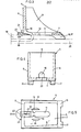
- FIG. 3 shows how the steel bracket 19 holding an upper asbestos cement plate 18 engages in the snow holding device 5.
- the snow holding device rests with the heels 16 and 17 on a lower asbestos cement plate 20.
- the support part 7 is semicircular continued in the form of the retaining part 6.
- the opening 11 in the support part 7 runs obliquely in the region of the semicircular extension 22.
- the steel bracket 19 When the snow guard is installed on the roof, the steel bracket 19 is inserted into the end of the elongated opening 11 of the support part 7 facing the paragraphs 16 and 17.
- the two cams 12 and 13 When the snow guard 5 is pulled downwards, the two cams 12 and 13 are pressed apart in the opening 11 of the support part 7, the bracket end 21 sliding into the end of the opening 11 facing the retaining part 6 and being held firmly after the cams 12 and 13 spring back.
- the crescent-shaped slots 14 and 15 allow the cams 12 and 13 to move laterally.
Abstract
Description
Es sind Schneehaltevorrichtungen, insbesondere für Asbestzement-Dächer bekannt, bei welchen der Befestiqungsteil einen Fortsatz des Schneerückhalteteils bildet. Dieser Befestigungsteil ist mit einer Oeffnung zum Eingreifen eines Die Asbestzement-Platten haltenden Stahlbügels bestimmt. Die zum Eingreifen des Stahlbügels bestimmte Stelle im Befestigungsteil dieser bekannten Schneefanqvorrichtung bildet jedoch die schwächste Zone der Schneefangvorrichtung.Snow holding devices, in particular for asbestos cement roofs, are known in which the fastening part forms an extension of the snow holding part. This fastening part is designed with an opening for engaging a steel bracket holding the asbestos cement plates. However, the point in the fastening part of this known snow guard device intended to engage the steel bracket forms the weakest zone of the snow guard device.
Es ist eine Aufgabe der vorliegenden Erfindung eine Schneefangvorrichtung mit einem Befestigungsteil zu schaffen, bei dem die Bildung der Bruchstellen im montierten Zustand vermieden werden können. Dies wird erfindunqsgemäss dadurch erzielt, dass im Rückhalteteil und im Auflageteil Öeffnungen zum Einführen eines Bügels vorgesehen sind.It is an object of the present invention to provide a snow guard device with a fastening part in which the formation of the break points in the assembled state can be avoided. This is achieved according to the invention in that openings are provided in the retaining part and in the support part for inserting a bracket.
Bevorzugte Ausführungsbeispiele der Erfindung ergeben sich aus den abhängigen Ansprüchen.Preferred embodiments of the invention result from the dependent claims.
Im folgenden wird anhand der beiliegenden Zeichnunq ein Ausführungsbeispiel der Erfindung näher beschrieben. Es zeigen:
- Fig. 1 eine bekannte Schneefangvorrichtung in perspektivischer Ansicht
- Fiq. 2 eine bevorzugte Ausführunqsform der Schneefangvorrichtung gemäss der Erfindung in perspektivischer Ansicht, teilweise gebrochen
- Fiq. 3 einen Schnitt durch die Schneefangvorrichtung gemäss Fig. 2 gemäss Linie A-S der Fiq. 5
- Fiq. 4 die Schneefanqvorrichtung gemäss Fig. 2 in Vorderansicht
- Fig. 5 die Schneefangvorrichtung in Draufsicht
- Fig. 1 shows a known snow guard in a perspective view
- Fiq. 2 shows a preferred embodiment of the snow guard device according to the invention in a perspective view, partially broken
- Fiq. 3 shows a section through the
snow guard 2 according to line AS of Fiq. 5 - Fiq. 4 shows the snow attachment device according to FIG. 2 in a front view
- Fig. 5 shows the snow guard in plan view
Die bekannte Schneefangvorrichtung 1 gemäss Fig. 1 weist einen Schneerückhalteteil 1 und einen Befestigungsteil 3 auf. Im Befestigungsteil 3 ist eine Oeffnung 4 zum Einführen des um die Asbestzement-Platten gelegten Stahlbügels vorgesehen. Der Befestigungsteil ist relativ schwach ausgebildet, wobei die Gefahr der Bildung von Bruchstellen besteht.The known
Eine bevorzugte Ausführungsform 5 der erfindungsgemässen Schneefangvorrichtung qemäss den Fig. 2 - 5 umfasst einen Rückhalteteil 6, der bei der auf dem Dach montierten Schneehaltevorrichtung parallel zum First und senkrecht zu den Asbestzement-Platten verläuft. Der Rückhalteteil 6 ist rechtwinklig mit einem zur Auflage auf dem Dach bestimmten Auflageteil 7 verbunden. Zwei Seitenteile 8, 9 sind rechtwinklig mit dem Rückhalteteil 6 und dem Auflageteil 7 verbunden. Der Rückhalteteil 6 ist an seinem unteren, dem Auflageteil angrenzenden Ende in der Mitte mit einer halbkreisförmigen Oeffnung 10 versehen. Der Auflageteil weist in der Mittelachse eine längliche Oeffnung 11 auf, die etwa in der Mitte mit zwei Nocken 12 und 13 versehen ist. Im weiteren weist der Auflageteil 7 zwei zu beiden Seiten der länglichen Oeffnung liegende halbmondförmige Schlitze 14 und 15 auf. An dem dem Rückhalteteil 6 entgegengesetzten Ende des Auflageteils 7 sind Absätze 16 und 17 vorgesehen.A
Aus Fig. 3 ist ersichtlich, wie der eine obere Asbestzement-Platte 18 haltende Stahlbügel 19 in die Schneehaltevorrichtung 5 eingreift. Die Schneehaltevorrichtung liegt mit den Absätzen 16 und 17 auf einer unteren Asbestzement-Platte 20 auf. Zur besseren Halterunq des Bügelsendes 21 ist der Auflageteil 7 halbkreisförmig über den Rückhalteteil 6 forgesetzt. Die Oeffnung 11 im Auflageteil 7 verläuft im Bereich des halbkreisförmigen Ansatzes 22 schräg.3 shows how the
In Fig. 4 ist die Schneefangvorrichtung in Vorderansicht, d.h. im montierten Zustand in einer Ansicht von Dachfirst gegen die Dachtraufe, dargestellt.In Fig. 4 the snow guard is in front view, i.e. shown in the assembled state in a view from the ridge against the eaves.
Wie aus den Fig. 2 und 5 ersichtlich, ist der abgeschrägte Teil 23 des Auflageteils mit einer mittleren Rille 24 versehen. Diese Rille 24 dient zur besseren Halterung des Stahlbügelendes 21 im abgeschrägten Teil 23. Ein seitliches Verrutschen wird damit vermieden.As can be seen from FIGS. 2 and 5, the
Bei der Montage der Schneefangvorrichtung auf dem Dach wird der Stahlbügel 19 in das den Absätzen 16 und 17 zugewandte Ende der länglichen Oeffnung 11 des Auflageteils 7 eingeführt. Beim dachabwärts Ziehen der Schneefangvorrichtung 5 werden die beiden Nocken 12 und 13 in der Oeffnung 11 des Auflageteils 7 auseinandergedrückt, wobei das Bügelende 21 in das dem Zurückhalteteil 6 zugewandte Ende der Oeffnung 11 gleitet und nach dem Zurückfedern der Nocken 12 und 13 fest gehalten wird. Die halbmondförmigen Schlitze 14 und 15 ermöglichen eine seitliche Bewegung der Nocken 12 und 13.When the snow guard is installed on the roof, the
Durch die Ausbildung der Absätze 16 und 17 am Auflageteil 7 kann eine eventuell schädliche Wasseransammlung zwischen den Asbestzement-Platten und der Schneefangvorrichtung vermieden werden.The formation of the
Claims (4)
Priority Applications (1)
| Application Number | Priority Date | Filing Date | Title |
|---|---|---|---|
| AT81810450T ATE13210T1 (en) | 1980-11-11 | 1981-11-11 | SNOW DETECTION DEVICE FOR ROOFS. |
Applications Claiming Priority (2)
| Application Number | Priority Date | Filing Date | Title |
|---|---|---|---|
| CH837180A CH655538B (en) | 1980-11-11 | 1980-11-11 | |
| CH8371/80 | 1980-11-11 |
Publications (3)
| Publication Number | Publication Date |
|---|---|
| EP0052080A2 true EP0052080A2 (en) | 1982-05-19 |
| EP0052080A3 EP0052080A3 (en) | 1983-01-05 |
| EP0052080B1 EP0052080B1 (en) | 1985-05-08 |
Family
ID=4339290
Family Applications (1)
| Application Number | Title | Priority Date | Filing Date |
|---|---|---|---|
| EP81810450A Expired EP0052080B1 (en) | 1980-11-11 | 1981-11-11 | Snow trap for roofs |
Country Status (4)
| Country | Link |
|---|---|
| EP (1) | EP0052080B1 (en) |
| AT (1) | ATE13210T1 (en) |
| CH (1) | CH655538B (en) |
| DE (1) | DE3170429D1 (en) |
Cited By (5)
| Publication number | Priority date | Publication date | Assignee | Title |
|---|---|---|---|---|
| EP0377407A1 (en) * | 1988-12-29 | 1990-07-11 | Siegfried Willa | Snow-retaining device |
| EP0384952A1 (en) * | 1989-02-27 | 1990-09-05 | Guido Marquart | Roof snow guard |
| EP0389438A1 (en) * | 1989-03-23 | 1990-09-26 | Neomat Ag | Snowguard |
| EP0388575A1 (en) * | 1989-03-23 | 1990-09-26 | Neomat Ag | Snow guard |
| US7174677B1 (en) * | 2003-09-17 | 2007-02-13 | Amerimax Home Products, Inc. | Snow guard for shingled roofs |
Citations (4)
| Publication number | Priority date | Publication date | Assignee | Title |
|---|---|---|---|---|
| CH514760A (en) * | 1970-12-12 | 1971-10-31 | Kuenzle David | Snow protection device for slab roofs |
| CH522103A (en) * | 1970-04-13 | 1972-04-30 | Meyer Rene | Roof snow retainer |
| DE2522018A1 (en) * | 1975-05-17 | 1976-12-02 | Paech Peter | Concrete structure reinforcing elements spacer - incorporating cement-content base, and connecting element shaped to fit reinforcement |
| CH620961A5 (en) * | 1977-05-20 | 1980-12-31 | Glaromat Ag | Snow guard |
-
1980
- 1980-11-11 CH CH837180A patent/CH655538B/de unknown
-
1981
- 1981-11-11 AT AT81810450T patent/ATE13210T1/en not_active IP Right Cessation
- 1981-11-11 DE DE8181810450T patent/DE3170429D1/en not_active Expired
- 1981-11-11 EP EP81810450A patent/EP0052080B1/en not_active Expired
Patent Citations (4)
| Publication number | Priority date | Publication date | Assignee | Title |
|---|---|---|---|---|
| CH522103A (en) * | 1970-04-13 | 1972-04-30 | Meyer Rene | Roof snow retainer |
| CH514760A (en) * | 1970-12-12 | 1971-10-31 | Kuenzle David | Snow protection device for slab roofs |
| DE2522018A1 (en) * | 1975-05-17 | 1976-12-02 | Paech Peter | Concrete structure reinforcing elements spacer - incorporating cement-content base, and connecting element shaped to fit reinforcement |
| CH620961A5 (en) * | 1977-05-20 | 1980-12-31 | Glaromat Ag | Snow guard |
Cited By (5)
| Publication number | Priority date | Publication date | Assignee | Title |
|---|---|---|---|---|
| EP0377407A1 (en) * | 1988-12-29 | 1990-07-11 | Siegfried Willa | Snow-retaining device |
| EP0384952A1 (en) * | 1989-02-27 | 1990-09-05 | Guido Marquart | Roof snow guard |
| EP0389438A1 (en) * | 1989-03-23 | 1990-09-26 | Neomat Ag | Snowguard |
| EP0388575A1 (en) * | 1989-03-23 | 1990-09-26 | Neomat Ag | Snow guard |
| US7174677B1 (en) * | 2003-09-17 | 2007-02-13 | Amerimax Home Products, Inc. | Snow guard for shingled roofs |
Also Published As
| Publication number | Publication date |
|---|---|
| EP0052080A3 (en) | 1983-01-05 |
| CH655538B (en) | 1986-04-30 |
| EP0052080B1 (en) | 1985-05-08 |
| DE3170429D1 (en) | 1985-06-13 |
| ATE13210T1 (en) | 1985-05-15 |
Similar Documents
| Publication | Publication Date | Title |
|---|---|---|
| EP1767791B1 (en) | Clamping device for gratings | |
| EP2828588B1 (en) | Solar module bracket | |
| DE3115060A1 (en) | BRACKET FOR FIXING ELECTRICAL LADDERS OR TUBES ON A PAD | |
| DE3617911A1 (en) | FASTENING ELEMENT FOR TUBING DIFFERENT DIAMETERS | |
| EP0377407B1 (en) | Snow-retaining device | |
| EP2249102A2 (en) | Connector for a profile rail | |
| EP0052080A2 (en) | Snow trap for roofs | |
| DE4242704C2 (en) | Device for fastening electrical installation devices | |
| DE4300415C2 (en) | Reflector connector for a light band | |
| DE2659788C2 (en) | Ventilation device for roofs covered with roof tiles | |
| EP1201844B1 (en) | Snow trap hook | |
| DE2438480A1 (en) | ANCHORING FOR TRACK RAILS | |
| DE2601848A1 (en) | Fixing for electrical terminal insulating block - has resilient edges placed around mounting rail edges and pulled in by centre screw | |
| DE4310420C1 (en) | Device for fastening ridge coverings on the roof ridge of a roof covering | |
| EP3348735B1 (en) | Retaining clip for a roofing plate | |
| EP3623722A1 (en) | Roof hook | |
| EP4239261A2 (en) | Roof hook | |
| EP0524504A1 (en) | Rectangular concrete building element with channel shaped cavity for the production of a sealed guttering system | |
| EP0864808B1 (en) | Mounting device for recessed lighting fixture | |
| AT523631B1 (en) | Device for fastening an end strip | |
| DE202004013226U1 (en) | Adapter for installing electronic devices, especially frequency converters, has attachment part(s) with elements(s) for attaching part, different attachment elements for attaching to fitting point | |
| DE102006044993A1 (en) | Clamp for shifting flat strip conductors on flat roofs, has base body, supported on flat roof for receiving flat strip conductor and cover with locking screw, where base body has base plate, and U blade extends in angle of ninety degree | |
| EP0801184A2 (en) | Snowguard | |
| DE19744114C1 (en) | Kit for the renovation of roofs covered with corrugated sheets - especially corrugated asbestos fiber cement sheets | |
| EP0389438B1 (en) | Snowguard |
Legal Events
| Date | Code | Title | Description |
|---|---|---|---|
| PUAI | Public reference made under article 153(3) epc to a published international application that has entered the european phase |
Free format text: ORIGINAL CODE: 0009012 |
|
| AK | Designated contracting states |
Designated state(s): AT CH DE FR IT LI |
|
| PUAL | Search report despatched |
Free format text: ORIGINAL CODE: 0009013 |
|
| AK | Designated contracting states |
Designated state(s): AT CH DE FR IT LI |
|
| 17P | Request for examination filed |
Effective date: 19830314 |
|
| ITF | It: translation for a ep patent filed |
Owner name: UFFICIO TECNICO ING. A. MANNUCCI |
|
| GRAA | (expected) grant |
Free format text: ORIGINAL CODE: 0009210 |
|
| AK | Designated contracting states |
Designated state(s): AT CH DE FR IT LI |
|
| REF | Corresponds to: |
Ref document number: 13210 Country of ref document: AT Date of ref document: 19850515 Kind code of ref document: T |
|
| REF | Corresponds to: |
Ref document number: 3170429 Country of ref document: DE Date of ref document: 19850613 |
|
| ET | Fr: translation filed | ||
| PLBE | No opposition filed within time limit |
Free format text: ORIGINAL CODE: 0009261 |
|
| STAA | Information on the status of an ep patent application or granted ep patent |
Free format text: STATUS: NO OPPOSITION FILED WITHIN TIME LIMIT |
|
| 26N | No opposition filed | ||
| ITTA | It: last paid annual fee | ||
| PGFP | Annual fee paid to national office [announced via postgrant information from national office to epo] |
Ref country code: AT Payment date: 19951130 Year of fee payment: 15 |
|
| PGFP | Annual fee paid to national office [announced via postgrant information from national office to epo] |
Ref country code: FR Payment date: 19961108 Year of fee payment: 16 |
|
| PG25 | Lapsed in a contracting state [announced via postgrant information from national office to epo] |
Ref country code: AT Effective date: 19961111 |
|
| PGFP | Annual fee paid to national office [announced via postgrant information from national office to epo] |
Ref country code: CH Payment date: 19961114 Year of fee payment: 16 |
|
| PGFP | Annual fee paid to national office [announced via postgrant information from national office to epo] |
Ref country code: DE Payment date: 19961125 Year of fee payment: 16 |
|
| PG25 | Lapsed in a contracting state [announced via postgrant information from national office to epo] |
Ref country code: LI Free format text: LAPSE BECAUSE OF NON-PAYMENT OF DUE FEES Effective date: 19971130 Ref country code: FR Free format text: THE PATENT HAS BEEN ANNULLED BY A DECISION OF A NATIONAL AUTHORITY Effective date: 19971130 Ref country code: CH Free format text: LAPSE BECAUSE OF NON-PAYMENT OF DUE FEES Effective date: 19971130 |
|
| REG | Reference to a national code |
Ref country code: CH Ref legal event code: PL |
|
| PG25 | Lapsed in a contracting state [announced via postgrant information from national office to epo] |
Ref country code: DE Free format text: LAPSE BECAUSE OF NON-PAYMENT OF DUE FEES Effective date: 19980801 |
|
| REG | Reference to a national code |
Ref country code: FR Ref legal event code: ST |