EP0052058A1 - Device for the detection of faults in a metallic product by means of eddy currents - Google Patents
Device for the detection of faults in a metallic product by means of eddy currents Download PDFInfo
- Publication number
- EP0052058A1 EP0052058A1 EP81401780A EP81401780A EP0052058A1 EP 0052058 A1 EP0052058 A1 EP 0052058A1 EP 81401780 A EP81401780 A EP 81401780A EP 81401780 A EP81401780 A EP 81401780A EP 0052058 A1 EP0052058 A1 EP 0052058A1
- Authority
- EP
- European Patent Office
- Prior art keywords
- product
- probe
- windings
- vector
- voltage
- Prior art date
- Legal status (The legal status is an assumption and is not a legal conclusion. Google has not performed a legal analysis and makes no representation as to the accuracy of the status listed.)
- Granted
Links
Images


Classifications
-
- G—PHYSICS
- G01—MEASURING; TESTING
- G01N—INVESTIGATING OR ANALYSING MATERIALS BY DETERMINING THEIR CHEMICAL OR PHYSICAL PROPERTIES
- G01N27/00—Investigating or analysing materials by the use of electric, electrochemical, or magnetic means
- G01N27/72—Investigating or analysing materials by the use of electric, electrochemical, or magnetic means by investigating magnetic variables
- G01N27/82—Investigating or analysing materials by the use of electric, electrochemical, or magnetic means by investigating magnetic variables for investigating the presence of flaws
- G01N27/90—Investigating or analysing materials by the use of electric, electrochemical, or magnetic means by investigating magnetic variables for investigating the presence of flaws using eddy currents
- G01N27/9046—Investigating or analysing materials by the use of electric, electrochemical, or magnetic means by investigating magnetic variables for investigating the presence of flaws using eddy currents by analysing electrical signals
Definitions
- the product scrolls. It applies in particular to the control of round bars inside a straightener forming part of a drawing chain and giving these bars a helical scrolling movement.
- the invention therefore aims to provide a detection method for industrially using a probe kept out of contact with the product to be controlled.
- the subject of the invention is a method of detecting by eddy currents faults in a metal product passing in front of a point probe comprising two windings in series, in particular inside a straightening machine, characterized in that the two windings are arranged asymmetrically with respect to the product to be checked, an alternating electro-magnetic field is symmetrically produced in these two windings, the voltage induced at the terminals of the two windings is measured, and variations in the argument of the rotating vector representative of this voltage with respect to the inductive voltage vector.
- the invention also relates to a device for implementing this method.
- These measures comprises at least one probe comprising the two windings in series arranged at different distances from the product, an inductor winding arranged so as to generate in the two windings opposite magnetic fields, means for sensing the voltage across these two windings, and an electronic circuit for detecting the variation of the argument of the vector representative of this voltage with respect to the inductive voltage.
- the probe, or the first probe in the direction of travel of the product is arranged downstream or in the region from where the product leaves the hyperbolic roller. .
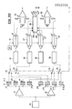
- the probe 1 of FIG. 1 has the shape of an H perpendicular to the metallic product 2 to be checked, which passes before it in relative motion.
- the two branches 3 of the H terminate at the same distance from the product 2, and its core 4 is parallel to the latter.
- the core 4 carries a winding inductor 5, while a branch 3 carries two windings 6, 7 mounted in series, placed symmetrically with respect to the winding 5 and wound in the same direction.
- the winding 5 is connected to an alternating voltage source and generates a magnetic field at each instant in the two halves of the H. This field crosses the windings 6 and 7 in opposite directions, as illustrated in FIG. 1. The variation of this field induced in the windings 6 and 7 of the alternative f.é.m.
- This alternating voltage can be represented by a rotating vector V (Fig. 2) of module r and of argument or phase shift 6 with respect to the vector inductive voltage ⁇ .
- the values of r and ⁇ depend on the distance D from the product 2 to the probe 1. We have shown in FIG. 2 the location of the ends of the vector V, the origin O corresponding to an infinite distance and the points V 1 to V 4 at increasingly small distances D.
- Fig. 6 shows the location of the probe in a straightening machine with two rollers.
- the straightening machine comprises a cylindrical roller 8 and a hyperbolic roller 9 rotating in the same direction and whose horizontal axes are oblique, oriented in opposite directions and cut the vertical plane of symmetry P of the machine in the same transverse plane which is the plane of Fig. 6.
- the probe 1 is located in this transverse plane, or in the vicinity of this plane, in practice within the limits of the rollers 8 and 9 in order to have an acceptable vibration of the product 2.
- the machine further comprises two fixed horizontal guide strips 10 and 11.
- the strip 10 which faces the direction of rotation of the hyperbolic roller 9 is only attacked by the ends of the product 2, while the running part of it only comes into contact with the opposite strip 11.
- the probe 1 is embedded in the strip 10 and is protected by an interchangeable part 12.
- FIG. 8A for the probe, the & variationsde a function of time t: ⁇ from a value depending on the setting of the straightening machine, it was reported the effect of vibration of the product ( ⁇ ⁇ 'a) and the passage of a fault1 ( ⁇ ⁇ a ); the F ig. 8B is the corresponding curve- ( ⁇ b, ⁇ ⁇ 'b , ⁇ ⁇ b ) for the probe 1 b , the opposite of this curve being shown in dotted lines, and FIG. 8C is the curve corresponding to the subtraction of the curves of Figs. 8A and 8B.
- the two probes l a , l b are offset longitudinally so that increase the length of bar they cover.
- the total thickness of the one or two probes is at most equal to the diameter of the bar 2.
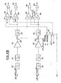
- FIGS. 9A to 9C the electronic detection equipment associated with two pairs of probes 1a- 1b and 1 c- 1 d .
- the mechanical connections are shown in mixed lines.
- the analog connections are dotted, and the logical connections in solid lines.
- the entire electronic circuit can be connected by four switches 13 either to the four probes 1a to I d , or to four other analogous probes a to 1 ' d arranged in the same way but in a location outside the straightener. These four other probes are used to calibrate the circuit by scanning a section of bar driven in rotation but fixed in translation and having a well-defined defect.
- An oscillator 14 feeds via power amplifiers 15 one or the other of the two groups of four probes.
- the frequency of oscillator 14 has been adjusted to 100 kHz, which leads to practically purely angular variations of the vector V.
- the voltages V collected at the terminals of each probe, after having been preamplified by a preamplification module incorporated into each probe, are sent to the processing cabinet containing the electronic circuit.
- the circuit 18 compares the modules r with values corresponding to two predetermined distances minimum d m and maximum d M and outputs four logical pieces of information d to d d . If the distance of product 2 to the probe concerned is greater than d M , it is considered that this product is absent; if it is less than d, this corresponds to excessive wear of the protective part 12.
- the passage of one of the pieces of information d a to d d from 0 to 1 corresponds to a distance between product and probe between d m and d M , that is to say the presence of a bar in front of the probe and a good protection of the latter, and closes the switch 23, which avoids further processing the erratic signals appearing in the no bar. It will be assumed below that the switch 23 is closed.
- the signal After filtering in a high-pass filter 24, the signal approaches the logic part of the electronic circuit arriving at two comparators 25, 26 where it is compared with two thresholds respectively.
- the comparator 25 receives a threshold Y1 and the comparator 26 a threshold of + 15 Volts much higher than the signals which can be received, so that only the first comparator supplies signals of: output.
- the two comparators receive thresholds Y1 and Y2 corresponding to two degrees of severity of the control.
- the aforementioned four thresholds are obtained by means of a double switch 27 coupled to the switches 13.
- each comparator 25, 26, applied to an input of two AND gates 28, 29 respectively, thus provides logic signals representative of disturbing phenomena of amplitude at least equal to a predetermined value.
- the rest of the circuit is used to detect whether or not these are product faults. Indeed, a signal output of the comparators 25, 26 can be generated not only by a metallurgical defect of the type sought, but also by the influence of the ends of the product to be checked on the probes or by a disturbing phenomenon of electrical or mechanical origin.
- the speed of the cylindrical roller 8 is measured with a tachometric dynamo 30 associated with an adjustment potentiometer 30 '.
- V G the linear speed of product 2.
- the signals leaving registers 36 and 37 are combined, through an OR gate 38, 39 respectively, with the corresponding signals relating to the two other probes l c and 1 d , and reach a device 40 for counting, memorizing and commanding marking .
- Various decisions can then be taken as to the fate of the bars checked, depending on the number of faults above the two thresholds, thanks to counters 41, a sorting command 42 and a command to mark the bars 43 connected to the device 40.
- the device 40 also makes it possible to evaluate the dimensions of the defects detected.
- the correlation circuit 33 is intended to eliminate parasitic signals of electrical or mechanical origin. For this, this circuit memorizes each signal received, then on the appearance of a second signal, it checks that it corresponds to the same place on the bar, or to another place located on the same generator. If so, and only in this case, the signal is validated and treated as corresponding to a fault.
- the circuit 33 which is common to the two pairs of probes 1 a -1 b and 1 c -1 d , comprises a shift register controlled by a natural frequency proportional to the speed of rotation of the bar.
- the factor K 2 incorporates the inclination of the rollers, which determines the pitch of the helix advance propeller.
- the passage time of the above-mentioned shift register is equal to the rotation time of the bar 2.
- a device 45 for monitoring the probes which checks the almost simultaneous passage of 0 to 1 and from 1 to 0 of the signals d a to d d .
- This device is linked to appropriate security and alarm devices 46.
- the electronic device of Figs. 9A to 9C includes a certain number of suitable test points making it possible to measure the signals at these points. These test points have not been shown for the sake of clarity.
- each probe may differ from one H.
- the probe may include an additional branch perpendicular to the product 2, the middle branch carrying the two windings 6 and 7.
- the invention applies to the control of metallic products other than round bars such as bars having another shape in section or strips.
- the controlled product can be fixed and the probe (s) mobile so as to scan the entire surface of the product.
- the probe can be mounted on a rotary support to control a round bar moving in translation along the axis of rotation of this support.
- the straightener comprises an upper cylindrical roller 8 and a lower hyperbolic roller 9 rotating in the same direction and whose respective axes XX and YY are horizontal and oblique, oriented in opposite directions, and intersect the vertical plane of symmetry P of the machine in the same transverse vertical plane Q, which is the plane of Fig. 11.
- the machine also has two fixed horizontal guide strips 10 and 11.
- the strip 10 which faces the direction of rotation of the hyperbolic roller 9 is only attacked by the ends of the product 2 to be checked, which is a bar round animated by a horizontal scrolling movement following the arrows shown in Figs.
- the probe 1 is embedded in the strip 10 and is protected by an interchangeable part 12.
- the probe 1 is connected by electrical wires 100 to the electronic circuit described above.
- the tests have shown that the plane Q was not at all the most favorable location for the detection of faults according to the method described with reference to FIGS. 1 to 9C, because when the probe is in this plane or in its vicinity, one obtains a strong background noise, which can reach a level sufficient to prevent discrimination of the signals generated by the metallurgical defects sought.
- the optimal arrangement consists in installing the first probe, or upstream probe, opposite point C.
- the stresses generated by this bending between points B and C are maximum at point A and are added to the compression stresses generated by the tightening of the rollers and to the internal mechanical tensions generated by machining (stretching, peeling and straightening).
- the resulting stresses vary due to the displacement of the bar and generate signals which are added to those generated by the structure, mechanical vibrations and possible faults.
- the background noise is increased irregularly but all the more important as the stresses are higher.
- point C is the point devoid of bending and compression constraints where the vibration of product 2 is minimal.
Abstract
Description
La présente invention est relative au contrôle non destructif de produits métalliques par courants de Foucault au moyen d'une sonde ponctuelle devant laquel= . le défile le produit. Elle s'applique en particulier au contrôle de barres rondes à l'intérieur d'une dresseuse faisant partie d'une chaîne d'étirage et conférant à ces barres un mouvement hélicoïdal de défilement.The present invention relates to the non-destructive testing of metallic products by eddy currents by means of a point probe in front of which =. the product scrolls. It applies in particular to the control of round bars inside a straightener forming part of a drawing chain and giving these bars a helical scrolling movement.
Il a été proposé (brevet FR 2 218 146) d'intégrer une sonde comportant deux enroulements en série dans une dresseuse, à l'emplacement où les vibrations de la barre sont minimales et où la vitesse de défilement est constante. La sonde est appliquée élastiquement sur la barre et rétractée lors de l'entrée et de la sortie de celle-ci.It has been proposed (
Cette solution présente de graves inconvénients:
- - lorsque des produits à contrôler se déplacent, notamment dans le cas des dresseuses, ils soumettent leurs organes de guidage à des chocs importants lors de leur entrée et de leur sortie. Ces chocs peuvent endommager le dispositif de mise en appui de la sonde;
- - en cours de contrôle, la sonde peut être endommagée par de gros défauts de la barre;
- - un dérèglement ou une avarie du système de commande de mise en contact des sondes peut entraîner leur destruction immédiate;
- - la présence et l'accumulation de boues, résultant du mélange des liquides de lubrification avec les particules métalliques "décollées" du produit par les contraintes de dressage, sont de nature à empêcher très rapidement le fonctionnement des mécanismes de. commande des sondes;
- - le principe d'effacer les sondes à l'entrée et à la sortie élimine le contrôle d'une zone importante aux extrémités de la barre.
- - When the products to be checked move, in particular in the case of straighteners, they subject their guide members to strong shocks during their entry and exit. These shocks can damage the support device of the probe;
- - during the check, the probe may be damaged by large defects in the bar;
- - an imbalance or damage to the sensor contacting control system can lead to their immediate destruction;
- - The presence and accumulation of sludge, resulting from the mixture of lubrication liquids with the metallic particles "peeled off" from the product by the dressing constraints, are likely to very quickly prevent the operation of the mechanisms. control of probes;
- - the principle of erasing the probes at the entrance and at the exit eliminates the control of a large area at the ends of the bar.
Il serait souhaitable de pouvoir utiliser une sonde qui ne soit pas en contact avec le produit:
- on pourrait alors inspecter la quasi-totalité de la barre sans qu'aucun dispositif de déplacement de la sonde soit nécessaire et sans risque d'endommager cette sonde.
- we could then inspect almost all of the bar without any device for moving the probe is necessary and without risk of damaging this probe.
Cependant, on ne peut pas se contenter d'éloigner du produit la sonde du brevet français précité. En effet, dans ce cas, les variations de distance entre le produit et la sonde suivant les conditions de réglage de la dresseuse, lesquelles sont fonction des caractéristiques mécaniques désirées, les différencesd'élévation de température et d'état de contraintes du produit suivant ce réglage, ainsi que les petites vibrations inévitables du produit, rendent difficile l'obtention d'une sensibilité de détection constante, d'autant plus que l'intervalle entre la sonde et le produit a pour conséquence un mauvais couplage électro-magnétique.However, it is not enough to distance the probe from the above-mentioned French patent from the product. Indeed, in this case, variations in distance between the product and the probe according to the setting conditions of the straightening machine, which are depending on the desired mechanical properties, the difference s of elevated temperature and product constraints state according to this setting, as well as the inevitable small vibrations of the product, make it difficult to obtain a constant detection sensitivity, especially since the interval between the probe and the product results in poor electro-magnetic coupling.
L'invention a donc pour but de fournir un procédé de détection permettant d'utiliser industriellement une sonde maintenue hors de contact avec le produit à contrôler.The invention therefore aims to provide a detection method for industrially using a probe kept out of contact with the product to be controlled.
A cet effet, l'invention a pour objet un procédé de détection par courants de Foucault de défauts dans un produit métallique défilant devant une sonde ponctuelle comprenant deux enroulements en série, notamment à l'intérieur d'une dresseuse, caractérisé en ce qu'on dispose les deux enroulements de façon asymétrique par rapport au produit à contrôler, on engendre un champ électro-magnétique alternatif symétriquement dans ces deux enroulements, on mesure la tension induite aux bornes des deux enroulements, et on détecte les variations de l'argument du vecteur tournant représentatif de cette tension par rapport au vecteur tension inductrice.To this end, the subject of the invention is a method of detecting by eddy currents faults in a metal product passing in front of a point probe comprising two windings in series, in particular inside a straightening machine, characterized in that the two windings are arranged asymmetrically with respect to the product to be checked, an alternating electro-magnetic field is symmetrically produced in these two windings, the voltage induced at the terminals of the two windings is measured, and variations in the argument of the rotating vector representative of this voltage with respect to the inductive voltage vector.
L'invention a également pour objet un dispositif pour la mise en oeuvre de ce procédé. Ce dispositif comprend au moins une sonde comprenant les deux enroulements en série disposés à des distances différentes du produit, un enroulement inducteur disposé de façon à engendrer dans les deux enroulements des champs magnétiques opposés, des moyens de captage de la tension aux bornes de ces deux enroulements, et un circuit électronique de détection de la variation de l'argument du vecteur représentatif de cette tension par rapport à la tension inductrice.The invention also relates to a device for implementing this method. These measures comprises at least one probe comprising the two windings in series arranged at different distances from the product, an inductor winding arranged so as to generate in the two windings opposite magnetic fields, means for sensing the voltage across these two windings, and an electronic circuit for detecting the variation of the argument of the vector representative of this voltage with respect to the inductive voltage.
Dans un mode de réalisation qui s'est avéré conduire à des résultats de mesure optimaux, la sonde, ou la première sonde dans le sens de défilement du produit, est disposée en aval ou dans la région dù point où le produit quitte le galet hyperbolique.In an embodiment which has been found to lead to optimal measurement results, the probe, or the first probe in the direction of travel of the product, is arranged downstream or in the region from where the product leaves the hyperbolic roller. .
L'invention est exposée ci-après plus en détail à l'aide des dessins annexés, qui en représentent seulement un mode d'exécution. Sur ces dessins :
- la Fig. 1 est une vue schématique d'une sonde destinée à la mise en oeuvre de l'invention ;
- les Fig. 2 à 5 sont des diagrammes illustrant le procédé de détection de l'invention ;
- la Fig. 6 est un schéma d'implantation d'une sonde dans une dresseuse ;
- la Fig. 7 est une vue en perspective du positionnement de deux sondes pour la mise en oeuvre de l'invention;
- les Fig. 8A à 8C sont des courbes illustrant le traitement des informations fournies par les deux sondes de la Fig. 7 ;
- les Fig. 9A à 9C constituent ensemble un schéma du circuit électronique de traitement de signaux ;
- la Fig. 10 est une vue schématique en plan d'un dispositif de détection suivant un mode de réalisation préféré de l'invention, intégré à une dresseuse à deux galets ;
- la Fig. 11 est une vue prise en coupe suivant la ligne 11-11 de la Fig. 10.
- Fig. 1 is a schematic view of a probe intended for the implementation of the invention;
- Figs. 2 to 5 are diagrams illustrating the detection method of the invention;
- Fig. 6 is a diagram of implantation of a probe in a straightener;
- Fig. 7 is a perspective view of the positioning of two probes for the implementation of the invention;
- Figs. 8A to 8C are curves illustrating the processing of the information provided by the two probes of FIG. 7;
- Figs. 9A to 9C together constitute a diagram of the electronic signal processing circuit;
- Fig. 10 is a schematic plan view of a detection device according to a preferred embodiment of the invention, integrated into a straightener with two rollers;
- Fig. 11 is a view taken in section along line 11-11 of FIG. 10.
La sonde 1 de la Fig. 1 a la forme d'un H perpendiculaire au produit métallique 2 à contrôler, qui défile devant elle en mouvement relatif. Les deux branches 3 du H se terminent à la même distance du produit 2,et son âme 4 est parallèle à ce dernier.L'âme 4 porte un enroulement inducteur 5, tandis qu'une branche 3 porte deux enroulements 6, 7 montés en série, placés symétriquement par rapport à l'enroulement 5 et enroulés dans le même sens.The
L'enroulement 5 est relié à une source de tension alternative et engendre à chaque instant un champ magnétique dans les deux moitiés du H. Ce champ traverse en sens inverses les enroulements 6 et 7, comme illustré à la Fig. 1. La variation de ce champ induit dans les enroulements 6 et 7 des f.é.m.alternatives.The
En l'absence du produit 2, les f.é.m. induites s'annulent, de sorte qu'aucun signal électrique n'est engendré aux bornes des deux enroulements 6 et 7.In the absence of
Par contre, lorsque le produit 2 coupe les lignes de flux magnétique, il est le siège de courants de Foucault qui, à leur tour, créent un champ magnétique variable influençant essentiellement le flux magnétique le plus proche. La f.ê.m. induite dans l'enroulement 6 le plus proche du produit 2 est donc modifiée, de sorte qu'un signal de tension alternative V apparaît aux bornes des deux enroulements 6 et 7.On the other hand, when the
Cette tension alternative peut être représentée par un vecteur tournant V (Fig. 2) de module r et d'argument ou déphasage 6 par rapport au vecteur tension inductrice ø. Les valeurs de r et de θ dépendent de la distance D du produit 2 à la sonde 1. On a représenté à la Fig. 2 le lieu des extrémités du vecteur V, l'origine O correspondant à une distance infinie et les points V1 à V4 à des distances D de plus en plus faibles.This alternating voltage can be represented by a rotating vector V (Fig. 2) of module r and of argument or
Le passage d'un défaut du produit 2 proche de la surface de celui-ci provoque une modification rapide Δr, Δ θ du vecteur V. La Demanderesse a constaté que la valeur de Δ 0 est indépendante de la distance D pour un défaut donné, c'est-à-dire que Δ θ1Δ θ2= Δ θ3=Δ 6 4. De plus, un choix judicieux de la fréquence de la tension inductrice permet d'annuler pratiquement Δ r et donc de garantir que le déplacement du point représentatif est perpendiculaire au rayon-vecteur. La Fig. 4 montre dans cette hypothèse le lieu des points respectifs V'1 à V'4 au passage du défaut.The passage of a defect of the
Cette constatation fournit ainsi une méthode de détection des défauts qui n'est pas affectée par les variations de distance entre la sonde et le produit: on extrait l'argument θ du signal obtenu aux bornes des enroulements 6 et 7, et on détecte les variation Δ θ. Cette-méthode annule également les effets des variations de température et d'état de contraintes du produit 2 dues au réglage de la dresseuse; car ces effets ne se font sentir pratiquement que sur la valeur de θ et de r mais non sur celle de A θThis observation thus provides a method of detecting faults which is not affected by the variations in distance between the probe and the product: we extract the argument θ from the signal obtained at the terminals of the
Toutefois, ceci suppose une annulation parfaite du signal, c'est-à-dire un équilibrage parfait en l'absence du produit 2. En effet, comme on le voit à la Fig. 5, un déséquilibre initial, provoqué par la présence des masses métalliques avoisinantes, correspond à un décalage de l'origine pour les courbes lieux des points V1 à V4 et V'1 à V'4, ce qui conduit à une valeur non constante de Δ 9. Il est donc important d'effectuer une mesure préalable en l'absence du produit 2 et d'engendrer et d'appliquer aux bornes des enroulements 6 et 7 une tension alternative opposée à la tension obtenue.However, this supposes a perfect cancellation of the signal, that is to say a perfect balancing in the absence of the
La Fig. 6 montre l'implantation de la sonde dans une dresseuse à deux galets.La dresseuse comprend un galet cylindrique 8 et un galet hyperbolique 9 tournant dans le même sens et dont les axes horizontaux sont obliques, orientés en sens opposés et coupent le plan vertical de symétrie P de la machine dans un même plan transversal qui est le plan de la Fig.6. La sonde 1 est située dans ce plan transversal, ou au voisinage de ce plan, en pratique dans les limites des galets 8 et 9 pour avoir une vibration acceptable du produit 2.Fig. 6 shows the location of the probe in a straightening machine with two rollers. The straightening machine comprises a
La machine comporte de plus deux réglettes horizontales fixes de guidage 10 et 11. En service, la réglette 10 qui fait face au sens de rotation du galet hyperbolique 9 n'est attaquée que par les extrémités du produit 2, alors que la partie courante de celui-ci ne vient en contact qu' avec la réglette 11 opposée. La sonde 1 est noyée dans la réglette 10 et est protégée par une pièce interchangeable 12.The machine further comprises two fixed horizontal guide strips 10 and 11. In service, the
En pratique, on superpose deux sondes la et lb symétriquement par rapport au plan horizontal de défilement horizontal du produit 2, comme représenté à la Fig. 7. Ainsi, tous les phénomènes perturbateurs qui peuvent produire des signaux de variation de l'angle 6 (variations de structure du produit, vibrations, etc.) sont perçus de la même façon et simultanément par les deux sondes, tandis que les défauts du produit 2 agissent sur elles de la même façon mais avec un léger décalage dans le temps du fait du mouvement hélicoidal précité.In practice, two probes la and l b are superimposed symmetrically with respect to the horizontal plane of horizontal movement of the
On a ainsi représenté à la Fig. 8A, pour la sonde la, les variationsde & en fonction du temps t: à partir d'une valeur θa fonction du réglage de la dresseuse, on a indiqué l'effet d'une vibration du produit (Δ θ'a) et du passage d'un défautl (Δ θa) ; la Fig. 8B est la courbe correspondante-(θb, Δ θ'b, Δ θb ) pour la sonde 1b, l'opposé de cette courbe étant représenté en pointillé, et la Fig. 8C est la courbe correspondant à la soustraction des courbes des Fig. 8A et 8B. On voit que les valeurs de θa et θb d'une part, Δ θ'a et Δ θ'b d'autre part, s'annulent, et que seul subsiste le signal intéressant correspondant au défaut recherché, dont l'amplitude crête à crête est doublée (Δ 9a + Δ θb = 2 Δ θ).There is thus shown in FIG. 8A, for the probe, the & variationsde a function of time t: θ from a value depending on the setting of the straightening machine, it was reported the effect of vibration of the product (Δ θ 'a) and the passage of a fault1 (Δ θ a ); the F ig. 8B is the corresponding curve- (θ b, Δ θ 'b , Δ θ b ) for the
En pratique, on définit un coefficient de pondération K, voisin de 0,5 , choisi de façon à compenser les différences de réponse entre les circuits des deux sondes,et on calcule Δ θ = K θa= (1--K) θp.De plus,notamment pour les barres de gros diamètre,il est avantageux que les deux sondes la,lb soient décalées longitudinalement de façon à augmenter la longueur de barre qu'elles couvrent. De préférence également;l'épaisseur totale de la ou des deux sondes est au plus égale au diamètre de la barre 2.In practice, we define a weighting coefficient K, close to 0.5, chosen so as to compensate for the differences in response between the circuits of the two probes, and we calculate Δ θ = K θ a = (1 - K) θ p . In addition, in particular for large diameter bars, it is advantageous that the two probes l a , l b are offset longitudinally so that increase the length of bar they cover. Preferably also; the total thickness of the one or two probes is at most equal to the diameter of the
L'expérience montre que cette méthode,combinée avec un filtrage passe-haut à pente élevée de façon à ne conserverque les composantes à vari.ation rapide des signaux, donne d'excellents résultats dans l'évaluation des défauts, même dans le cas où le couplage magnétique entre la sonde et le produit à contrôler n'est pas optimal.Experience has shown that this method, combined with high-slope high-pass filtering so as to keep only the rapidly varying components of the signals, gives excellent results in the evaluation of faults, even in the case where the magnetic coupling between the probe and the product to be checked is not optimal.
Pour mieux évaluer l'importance des défauts du produit contrôlé, on peut utiliser plusieurs couples de sondes 1a-1b juxtaposés le long de l'axe de défilement du produit de part et d'autre du plan transversal de la Fig. 6; tous ces couples peuvent être incorporés à une même réglette 10 et protégés par une pièce 12 commune.To better evaluate the significance of defects in the controlled product can be used several pairs of
On décrira ci-dessous en regard des Fig. 9A à 9C l'appareillage électronique de détection associé à deux couples de sondes 1a-1b et 1c-1d. Sur ces Fig. 9A à 9C, on a représenté en traitsmixtes.les liaisons mécaniques, en pointillé les liaisons analogiques et en traits pleins les liaisons logiques.We will describe below with reference to FIGS. 9A to 9C the electronic detection equipment associated with two pairs of probes 1a- 1b and 1 c- 1 d . On these F ig. 9A to 9C, the mechanical connections are shown in mixed lines. The analog connections are dotted, and the logical connections in solid lines.
L'ensemble du circuit électronique peut être connecté par quatre commutateurs 13 soit aux quatre sondes 1a à Id, soit à quatre autres sondes analogues l'a à 1'd disposées de la même façon mais en un emplacement extérieur à la dresseuse. Ces quatre autres sondes servent à réaliser l'étalonnage du circuit par balayage d'un tronçon de barre entraîné en rotation mais fixe en translation et possédant un défaut bien défini.The entire electronic circuit can be connected by four
Un oscillateur 14 alimente par l'intermédiaire d'amplificateurs de puissance 15 l'un ou l'autre des deux groupes de quatre sondes. Dans une application réelle, on a réglé la fréquence de l'oscillateur 14 sur 100 kHz, ce qui conduit à des variations pratiquement purement angulaires du vecteur V.An
Les tensions V recueillies aux bornes de chaque sonde, après avoir été préamplifiées par un module de prëamplification incorporé à chaque sonde, sont envoyées vers l'armoire de traitement contenant le circuit électronique.The voltages V collected at the terminals of each probe, after having been preamplified by a preamplification module incorporated into each probe, are sent to the processing cabinet containing the electronic circuit.
La chaîne de traitement de chaque sonde comprend tout d'abord, en aval du commutateur 13 correspondant:
- -
un récepteur 16 qui a pour rôle principal de compenser rigoureusement la tension résiduelle de la sonde; et - - un phasemètre-
redresseur 17 qui extrait les coordonnées polaires du signal provenant du récepteur 16, à savoir le module r etl'argument 0. Cet argument est fourni par rapport au vecteurtension inductrice de référence 0 correspondant au fonctionnemetit de'l'osciliateur 14.
- - A
receiver 16 which main role is to rigorously compensate the residual voltage of the probe; and - - a phasemeter-
rectifier 17 which extracts the polar coordinates of the signal coming from thereceiver 16, namely the module r and theargument 0. This argument is provided with respect to the vector inductive voltage ofreference 0 corresponding to the function of theoscillator 14 .
En l'absence de produit, si r f 0, on synthétise au moyen de l'oscillateur 14 un vecteur de composantes (R, J) qui annule le vecteur analysé par le phasemètre-redresseur 17. Ensuite, en cours de contrôle d'une barre, le module r est fourni à un circuit de détermination de position 18 commun aux quatre sondes.In the absence of a product, if
Les arguments 0 correspondant à deux sondes d'un même couple, par exemple la et 1b, sont combinés dans un circuit de calcul 19 dont la sortie, qui correspond à Δ θ = K θa - (1-K) θb, est filtrée par des filtres passe- bas 20 et passe-haut 21 à pente raide, de manière à ne conserver qu'une bande passante déterminée correspondant aux signaux de défauts recherchés. Les signaux sont ensuite amplifiés par un amplificateur 22 et parviennent à un interrupteur 23.The
Le circuit 18 compare les modules r à des valeurs correspondant à deux distances prédéterminées minimale dm et maximale dM et sort quatre informations logiques d à dd. Si la distance du produit 2 à la sonde concernée est supérieure à dM, on considère que ce produit est absent; si elle est inférieure à d , ceci correspond à une usure excessive de la pièce de protection 12. Les passage de l'une des informations da à dd de 0 à 1 correspond à une distance produit - sonde comprise entre dm et dM, c'est-à-dire à la présence d'une barre devant la sonde et à une bonne protection de celle-ci,et ferme l'interrupteur 23, ce qui évite de traiter plus avant les signaux erratiques apparaissant en l'absence de barre. On supposera dans la suite que l'interrupteur 23 est fermé.The
Après filtrage dans un filtre passe-haut 24, le signal aborde la partie logique du circuit électronique en arrivant à deux comparateurs 25, 26 où il est comparé respectivement à deux seuils. En position "étalonnage", le comparateur 25 reçoit un seuil Y1 et le comparateur 26 un seuil de + 15 Volts très supérieur aux signaux pouvant être reçus, de sorte que seul le premier comparateur fournitdes signaux de :sortie . En position "contrôle", les deux comparateurs reçoivent des seuils Y1 et Y2 correspondant à deux degrés de sévérité du contrôle. Les quatre seuils précités sont obtenus au moyen d'un double commutateur 27 couplé aux commutateurs 13.After filtering in a high-
La sortie de chaque comparateur 25, 26,appliquée à une entrée de deux portes ET 28,29 respectivement, fournit ainsi des signaux logiques représentatifs de phénomènes perturbateurs d'amplitude au moins égale à une valeur prédéterminée. La suite du circuit sert à détecter s'il s'agit ou non de défauts du produit. En effet, un signal de sortie des comparateurs 25, 26 peut être engendré non seulement par un défaut métallurgique du type recherché, mais également par l'influence des extrémités du produit à contrôler sur les sondes ou par un phénomène perturbateur d'origine électrique ou mécanique.The output of each
On s'intéressera tout d'abord aux extrémités de la barre. On a vu que l'extrémité avant de la barre devant une sonde fait passer le signal d correspondant de 0 à 1. Cette information logique est appliquée à la deuxième entrée des portes ET 28, 29 après une temporisation T qui est fonction de la longueur L exclue du traitement à chaque extrémité de la barre. Plus précisément, cette temporisation correspond au défilement d'une longueur L de barre prédéterminée.We will first look at the ends of the bar. We have seen that the front end of the bar in front of a probe passes the corresponding signal d from 0 to 1. This logical information is applied to the second input of AND
Dans le cas d'une dresseuse à deux galets, on mesure avec une dynamo tachymétrique 30 associée à un potentiomètre d'ajustage 30' la vitesse du galet cylindrique 8. Cette tension, après pondération, est envoyée dans un convertisseur tension/fréquence 31 qui détermine la temporisation T, égale à un multiple de 1/F1 avec F1 = VG-. Kl/L où VG est la tension ajustée de la dynamo tachymétrique et K1.VG la vitesse linéaire du produit 2. Ainsi: ![]()
![]()
Ceci supprime les signaux non significatifs de début de contrôle correspondant à la longueur L en tête de barre. Les signaux restants sont envoyés d'une part, par une porte OU 32, à un circuit de corrélation 33, d'autre part à une entrée de deux autres portes ET 34, 35 commandées par le circuit 33. L'autre entrée de ces portes ET reçoit la sortie des portes ET 28, 29 respectivement, et leurs sorties parviennent respectivement à deux registres à décalage 36, 37. Ces registres ont une fréquence propre égale à la valeur F1 indiquée plus haut et un temps de passage égal au temps T précité.This eliminates the non-significant control start signals corresponding to the length L at the head of the bar. The remaining signals are sent on the one hand, by an
Lorsque l'extrémité arrière de la Parre franchit le couple de sondes 1a-1b , les signaux da et b reviennent à zéro . Ceci provoque la remise à zéro des registres 36 et 37 . Ainsi , les signaux entrant dans ces registres mais correspondant à la partie arrière de longueur L de la barre ne sortent pas des registres 36 et 37.When the rear end of the Parre crosses the pair of probes 1 a -1 b , the signals d a and b return to zero. This causes registers 36 and 37 to be reset to zero. Thus, the signals entering these registers but corresponding to the rear part of length L of the bar do not leave
Les signaux sortant des registres 36 et 37 sont combinés,à travers une porte OU 38, 39 respectivement,avec les signaux correspondants relatifs aux deux autres sondes lc et 1d,et parviennent à un dispositif 40 de comptage, mémorisation et commande de marquage. Diverses décisions peuvent alors être prises quant au sort des barres contrôlées, suivant le nombre de défauts supérieurs aux deux seuils, ce grâce à des compteurs 41, à une commande de tri 42 et à une commande de marquage des barres 43 reliées au dispositif 40. Le dispositif 40 permet également d'évaluer les dimensions des défauts détectés.The
Le circuit de corrélation 33 est destiné à éliminer les signaux parasites d'origine électrique ou mécanique. Pour cela, ce circuit mémorise chaque signal reçu, puis à l'apparition d'un second signal, il vérifie que celui-ci correspond au même endroit sur la barre, ou à un autre endroit situé sur la même génératrice. Dans l'affirmative, et seulement dans ce cas, le signal est validé et traité comme correspondant à un défaut.The
Pour cela, le circuit 33, qui est commun aux deux couples de sondes 1a-1b et 1c-1d, comprend un registre à décalage piloté par une fréquence propre proportionnelle à la vitesse de rotation de la barre. Dans le cas d'une dresseuse à deux galets, cette fréquence est F2 = VG x K2/D, où D est le diamètre de la barre contrôlée, et est fournie par un convertisseur tension/ fréquence 44 relié à la dynamo 30. Il est à noter que le facteur K2 incorpore l'inclinaison des galets, qui détermine le pas de l'hélice d'avance de la barre.For this, the
Le temps de passage du registre à décalage précité est égal au temps de rotation de la barre 2. Ainsi, si un signal correspond à un défaut, il est appliqué à la deuxième entrée des portes ET 34 et 35 en même temps que le second signal parvient à la première entrée de ces portes. Celles-ci s'ouvrent donc en délivrant un signal logique dans la suite du circuit.The passage time of the above-mentioned shift register is equal to the rotation time of the
Il est encore prévu un dispositif 45 de surveillance des sondes qui vérifie le passage à peu près simultané de 0 à 1 et de 1 à 0 des signaux da à dd. Ce dispositif est relié à des dispositifs de sécurité et d'alarme appropriés 46.There is also a
Le dispositif électronique des Fig. 9A à 9C comporte un certain nombre de points-tests appropriés permettant de mesurer les signaux en ces points. Ces points-tests n'ont pas été représentés, dans un but de clarté.The electronic device of Figs. 9A to 9C includes a certain number of suitable test points making it possible to measure the signals at these points. These test points have not been shown for the sake of clarity.
En variante, la forme de chaque sonde peut différer d'un H. En particulier, la sonde peut comporter une branche supplémentaire perpendiculaire au produit 2, la branche médiane portant les deux enroulements 6 et 7.As a variant, the shape of each probe may differ from one H. In particular, the probe may include an additional branch perpendicular to the
Bien entendu, l'invention s'applique au contrôle de produits métalliques autres que des barres rondes tels que des barres ayant une autre forme en section ou des feuillards. De plus, en variante, le produit contrôlé peut être fixe et la ou les sondes mobiles de façon à balayer toute la surface du produit. En particulier, la sonde peut être montée sur un support rotatif pour contrôler une barre ronde se déplaçant en translation le long de l'axe de rotation de ce support.Of course, the invention applies to the control of metallic products other than round bars such as bars having another shape in section or strips. In addition, as a variant, the controlled product can be fixed and the probe (s) mobile so as to scan the entire surface of the product. In particular, the probe can be mounted on a rotary support to control a round bar moving in translation along the axis of rotation of this support.
Dans la description ci-dessous du mode de réalisation des Fig. 10 et 11, on utilisera les mêmes numéros de référence que précédemment pour désigner les éléments correspondants.In the description below of the embodiment of Figs. 10 and 11, the same reference numbers will be used as above to designate the corresponding elements.
Comme dans le premier mode de réalisation, la dresseuse comprend un galet cylindrique supérieur 8 et un galet hyperbolique inférieur 9 tournant dans le même sens et dont les axes respectifs X-X et Y-Y sont horizontaux et obliques, orientés en sens opposés, et coupent le plan vertical de symétrie P de la machine dans un même plan vertical transversal Q, qui est le plan de la Fig.11.As in the first embodiment, the straightener comprises an upper
La machine comporte de plus deux réglettes horizontales fixes de guidage 10 et 11. En service, la réglette 10 qui fait face au sens de rotation du galet hyperbolique 9 n'est attaquée que par les extrémités du produit 2 à contrôler, qui est une barre ronde animée d'un mouvement de défilement horizontal suivant les flèches portées sur les Fig.The machine also has two fixed horizontal guide strips 10 and 11. In service, the
10 et 11, alors que la partie courante de celui-ci ne vient en contact qu'avec la réglette 11 opposée. La sonde 1 est noyée dans la réglette 10 et est protégée par une pièce interchangeable 12. La sonde 1 est reliée par des fils électriques 100 au circuit électronique décrit plus haut.10 and 11, while the current part thereof only comes into contact with the
La seule différence entre le dispositif représenté aux Fig. 10 et 11 et celui décrit précédemment réside dans la disposition de la sonde 1.The only difference between the device shown in Figs. 10 and 11 and that described above resides in the arrangement of the
En effet, dans le premier mode de réalisation, bien qu'il soit envisagé de disposer la sonde dans les limites des galets 8 et 9, on considérait comme seul facteur à prendre en compte pour l'implantation de la sonde la vibration du produit 2, de sorte que l'implantation préférée était le plan Q ou le voisinage de ce plan, suivant . l'enseignement du brevet FR 2 218 146 précité.Indeed, in the first embodiment, although it is envisaged to place the probe within the limits of the
Or, de façon surprenante,les essais ont montré que le plan Q n'était pas du tout l'emplacement le plus favorable pour la détection des défauts suivant le procédé décrit en regard des Fig. 1 à 9C, car lorsque la sonde se trouve dans ce plan ou dans son voisinage, on obtient un fort bruit de fond, qui peut atteindre un niveau suffisant pour empêcher la discrimination des signaux engendrés par les défauts métallurgiques recherchés.However, surprisingly, the tests have shown that the plane Q was not at all the most favorable location for the detection of faults according to the method described with reference to FIGS. 1 to 9C, because when the probe is in this plane or in its vicinity, one obtains a strong background noise, which can reach a level sufficient to prevent discrimination of the signals generated by the metallurgical defects sought.
Les essais ont montré que, par contre, le bruit de fond descend à un niveau tout à fait acceptable lorsque la sonde 1 se trouve en aval du point C où la barre 2 quitte le galet hyperbolique 9, du côté de sortie de la machine, la position optimale étant en regard de ce point C. Dans le cas d'utilisation de plusieurs sondes décalées longitudinalement, la disposition optimale consiste à installer la première sonde, ou sonde amont, en regard du point C.Tests have shown that, on the other hand, the background noise drops to a completely acceptable level when the
La Demanderesse pense que ce résultat peut s'expliquer de la façon suivante.The Applicant believes that this result can be explained as follows.
On sait que, dans une dresseuse à deux galets, la barre subit lors de l'opération de dressage une flexion entre le galet cylindrique et le galet hyperbolique en prenant appui sur le galet cylindrique 8 en un point A situé à peu près dans le plan médian Q et sur le galet hyperbolique 9 en deux points B et C proches des extrémités de ce galet. Bien entendu, les points A, B et C ne sont définis qu'approximativement, et c'est pourquoi ils ont été représentés par des zones ombrées à la Fig. 1. Le point C est le point défini plus haut.We know that, in a straightening machine with two rollers, the bar undergoes during the dressing operation a bending between the cylindrical roller and the hyperbolic roller by bearing on the
Les contraintes engendrées par cette flexion entre les points B et C sont maximales au point A et viennent s'ajouter aux contraintes de compression engendrées par le serrage des galets et aux tensions mécaniques internes engendrées par l'usinage (étirage, écroutage et dressage). Les contraintes résultantes varient du fait du déplacement de la barre et engendrent des signaux qui s'ajoutent à ceux engendrés par la structure, les vibrations mécaniques et les éventuels défauts. Le bruit de fond s'en trouve augmenté de façon irrégulière mais d'autant plus importante que les contraintes sont plus élevées.The stresses generated by this bending between points B and C are maximum at point A and are added to the compression stresses generated by the tightening of the rollers and to the internal mechanical tensions generated by machining (stretching, peeling and straightening). The resulting stresses vary due to the displacement of the bar and generate signals which are added to those generated by the structure, mechanical vibrations and possible faults. The background noise is increased irregularly but all the more important as the stresses are higher.
Ainsi, le point C est le point dépourvu de contraintes de flexion et de compression où la vibration du produit 2 est minimale.Thus, point C is the point devoid of bending and compression constraints where the vibration of
Claims (16)
Applications Claiming Priority (4)
| Application Number | Priority Date | Filing Date | Title |
|---|---|---|---|
| FR8024016A FR2493991A1 (en) | 1980-11-12 | 1980-11-12 | Eddy-current detection of flaws in metallic product - operates by moving helically in alternating magnetic field of series windings |
| FR8024016 | 1980-11-12 | ||
| FR8103726A FR2500632B2 (en) | 1980-11-12 | 1981-02-25 | DEVICE FOR DETECTING BY EDGE CURRENTS OF DEFECTS IN A METAL PRODUCT |
| FR8103726 | 1981-02-25 |
Publications (2)
| Publication Number | Publication Date |
|---|---|
| EP0052058A1 true EP0052058A1 (en) | 1982-05-19 |
| EP0052058B1 EP0052058B1 (en) | 1986-10-01 |
Family
ID=26222070
Family Applications (1)
| Application Number | Title | Priority Date | Filing Date |
|---|---|---|---|
| EP19810401780 Expired EP0052058B1 (en) | 1980-11-12 | 1981-11-10 | Device for the detection of faults in a metallic product by means of eddy currents |
Country Status (3)
| Country | Link |
|---|---|
| EP (1) | EP0052058B1 (en) |
| DE (1) | DE3175426D1 (en) |
| FR (1) | FR2500632B2 (en) |
Cited By (3)
| Publication number | Priority date | Publication date | Assignee | Title |
|---|---|---|---|---|
| EP0257603A2 (en) * | 1986-08-27 | 1988-03-02 | Törnbloms Kvalitetskontroll Ab | Device for eddy current testing of non-magnetic test objects |
| US4752739A (en) * | 1984-10-16 | 1988-06-21 | Stein Heurtey | Device for measuring the thickness of thin metallic layers deposited on a conductive support |
| WO2012110340A1 (en) * | 2011-02-15 | 2012-08-23 | Wafios Ag | Method and device for the automated straightening of elongate material |
Citations (8)
| Publication number | Priority date | Publication date | Assignee | Title |
|---|---|---|---|---|
| FR1308785A (en) * | 1961-10-13 | 1962-11-09 | Gkn Group Services Ltd | Improvements in methods and apparatus for detecting the presence of defects in electrically conductive coherent solids |
| FR2015382A1 (en) * | 1968-08-09 | 1970-04-24 | Republic Steel Corp | |
| GB1200146A (en) * | 1967-08-17 | 1970-07-29 | Friedrich M O Foerster | Measuring magnetic fields |
| US3535625A (en) * | 1968-04-22 | 1970-10-20 | Garrett Corp | Strain and flaw detector |
| FR2218146A1 (en) * | 1973-02-21 | 1974-09-13 | Foerster Inst Dr Friedrich | |
| US3916301A (en) * | 1974-05-20 | 1975-10-28 | Republic Steel Corp | Magnetic flaw detection apparatus |
| US4191922A (en) * | 1978-03-14 | 1980-03-04 | Republic Steel Corporation | Electromagnetic flaw detection system and method incorporating improved automatic coil error signal compensation |
| FR2449283A1 (en) * | 1979-02-12 | 1980-09-12 | Rizhskij Polt Inst | METHOD FOR NON-DESTRUCTIVE CONTROL OF THE QUALITY OF SPOT WELDINGS AND DEVICE FOR IMPLEMENTING SAME |
-
1981
- 1981-02-25 FR FR8103726A patent/FR2500632B2/en not_active Expired
- 1981-11-10 DE DE8181401780T patent/DE3175426D1/en not_active Expired
- 1981-11-10 EP EP19810401780 patent/EP0052058B1/en not_active Expired
Patent Citations (8)
| Publication number | Priority date | Publication date | Assignee | Title |
|---|---|---|---|---|
| FR1308785A (en) * | 1961-10-13 | 1962-11-09 | Gkn Group Services Ltd | Improvements in methods and apparatus for detecting the presence of defects in electrically conductive coherent solids |
| GB1200146A (en) * | 1967-08-17 | 1970-07-29 | Friedrich M O Foerster | Measuring magnetic fields |
| US3535625A (en) * | 1968-04-22 | 1970-10-20 | Garrett Corp | Strain and flaw detector |
| FR2015382A1 (en) * | 1968-08-09 | 1970-04-24 | Republic Steel Corp | |
| FR2218146A1 (en) * | 1973-02-21 | 1974-09-13 | Foerster Inst Dr Friedrich | |
| US3916301A (en) * | 1974-05-20 | 1975-10-28 | Republic Steel Corp | Magnetic flaw detection apparatus |
| US4191922A (en) * | 1978-03-14 | 1980-03-04 | Republic Steel Corporation | Electromagnetic flaw detection system and method incorporating improved automatic coil error signal compensation |
| FR2449283A1 (en) * | 1979-02-12 | 1980-09-12 | Rizhskij Polt Inst | METHOD FOR NON-DESTRUCTIVE CONTROL OF THE QUALITY OF SPOT WELDINGS AND DEVICE FOR IMPLEMENTING SAME |
Cited By (4)
| Publication number | Priority date | Publication date | Assignee | Title |
|---|---|---|---|---|
| US4752739A (en) * | 1984-10-16 | 1988-06-21 | Stein Heurtey | Device for measuring the thickness of thin metallic layers deposited on a conductive support |
| EP0257603A2 (en) * | 1986-08-27 | 1988-03-02 | Törnbloms Kvalitetskontroll Ab | Device for eddy current testing of non-magnetic test objects |
| EP0257603A3 (en) * | 1986-08-27 | 1989-05-31 | Törnbloms Kvalitetskontroll Ab | Device for eddy current testing of non-magnetic test objects |
| WO2012110340A1 (en) * | 2011-02-15 | 2012-08-23 | Wafios Ag | Method and device for the automated straightening of elongate material |
Also Published As
| Publication number | Publication date |
|---|---|
| EP0052058B1 (en) | 1986-10-01 |
| FR2500632B2 (en) | 1987-12-24 |
| FR2500632A2 (en) | 1982-08-27 |
| DE3175426D1 (en) | 1986-11-06 |
Similar Documents
| Publication | Publication Date | Title |
|---|---|---|
| EP0195794B1 (en) | Method for detecting surface defects by means of foucault currents and device for implementing such method | |
| EP2035822B1 (en) | Non-destructive testing by ultrasound of foundry products | |
| EP0195792B1 (en) | Method and device for detecting by using foucault currents typical defects on a product | |
| EP0021893B1 (en) | Method and apparatus for eddy current testing of metallic products and application of the method and apparatus | |
| EP0290513B1 (en) | Method for detecting thickness variations in the wall of a current conducting tubular body | |
| FR2548351A1 (en) | METHOD AND APPARATUS FOR NON-CONTACT MEASUREMENT OF A SOLIDIFIED SHELL OF A CAST-METALLIC PIECE | |
| EP0052058B1 (en) | Device for the detection of faults in a metallic product by means of eddy currents | |
| FR2495778A1 (en) | FAULT DETECTOR IN BEARING BALLS UTILIZING FOUCAULT CURRENTS | |
| FR2493991A1 (en) | Eddy-current detection of flaws in metallic product - operates by moving helically in alternating magnetic field of series windings | |
| EP0335757B1 (en) | Control process using impulsiv eddy currents, and device to use it | |
| WO1997026627A1 (en) | Device for selecting objects, particularly coins | |
| EP0236841B1 (en) | Method of measuring the relative elongation of an elongate magnetisable element of small traverse dimension,and apparatus for carrying out the method | |
| EP0987554B1 (en) | Measuring circuit | |
| FR2700661A1 (en) | Device for detecting foreign bodies, for a thresher | |
| CZ286896A3 (en) | Identification method of coins and apparatus for making the same | |
| JPH0772712B2 (en) | Measuring instrument for internal quality of fruits and vegetables by transmission method | |
| EP0061956B1 (en) | Method for eddy current non destructive testing with lift off correction and apparatus for using this method | |
| EP0736173B1 (en) | Method and device for magnetic testing of metal products | |
| EP0468905B1 (en) | Method and device for eddy-current testing of metal tubes during hot-rolling | |
| FR2811076A1 (en) | METHOD FOR MEASURING THE WALL THICKNESS OF A HOLLOW BLADE | |
| FR2466772A1 (en) | Non-destructive ultrasonic tube or rod testing - measuring end positions and suppressing undesired end signal | |
| EP0104113B1 (en) | Process and appliance for laterally positioning a member in relation to a seam formed between two metallic surfaces and presenting discontinuities | |
| FR2527104A1 (en) | METHOD FOR THE CLASSIFICATION SORTING OF A NUMBER OF SURFACE DEFECT-SPECIFIED WHEELS AND DEVICE FOR THE AUTOMATIC APPLICATION OF SAID METHOD | |
| FR2817352A1 (en) | Compliance control for flat screen network of conducting tracks, in which non contact periodic signal is injected onto tracks and detection signal is picked up using capacitive coupling between sensor and track | |
| JPH09159621A (en) | Surface inspection device |
Legal Events
| Date | Code | Title | Description |
|---|---|---|---|
| PUAI | Public reference made under article 153(3) epc to a published international application that has entered the european phase |
Free format text: ORIGINAL CODE: 0009012 |
|
| AK | Designated contracting states |
Designated state(s): DE GB IT SE |
|
| 17P | Request for examination filed |
Effective date: 19821116 |
|
| RAP1 | Party data changed (applicant data changed or rights of an application transferred) |
Owner name: INTERCONTROLE SOCIETE DITE: |
|
| GRAA | (expected) grant |
Free format text: ORIGINAL CODE: 0009210 |
|
| ITF | It: translation for a ep patent filed |
Owner name: BUGNION S.P.A. |
|
| AK | Designated contracting states |
Kind code of ref document: B1 Designated state(s): DE GB IT SE |
|
| REF | Corresponds to: |
Ref document number: 3175426 Country of ref document: DE Date of ref document: 19861106 |
|
| PLBE | No opposition filed within time limit |
Free format text: ORIGINAL CODE: 0009261 |
|
| STAA | Information on the status of an ep patent application or granted ep patent |
Free format text: STATUS: NO OPPOSITION FILED WITHIN TIME LIMIT |
|
| 26N | No opposition filed | ||
| PG25 | Lapsed in a contracting state [announced via postgrant information from national office to epo] |
Ref country code: SE Effective date: 19871111 |
|
| GBPC | Gb: european patent ceased through non-payment of renewal fee | ||
| PG25 | Lapsed in a contracting state [announced via postgrant information from national office to epo] |
Ref country code: DE Effective date: 19880802 |
|
| PG25 | Lapsed in a contracting state [announced via postgrant information from national office to epo] |
Ref country code: GB Effective date: 19881118 |
|
| EUG | Se: european patent has lapsed |
Ref document number: 81401780.2 Effective date: 19880913 |