EP0051938B1 - Video signal reproducing apparatus - Google Patents
Video signal reproducing apparatus Download PDFInfo
- Publication number
- EP0051938B1 EP0051938B1 EP81304942A EP81304942A EP0051938B1 EP 0051938 B1 EP0051938 B1 EP 0051938B1 EP 81304942 A EP81304942 A EP 81304942A EP 81304942 A EP81304942 A EP 81304942A EP 0051938 B1 EP0051938 B1 EP 0051938B1
- Authority
- EP
- European Patent Office
- Prior art keywords
- head
- signal
- jump
- track
- memory
- Prior art date
- Legal status (The legal status is an assumption and is not a legal conclusion. Google has not performed a legal analysis and makes no representation as to the accuracy of the status listed.)
- Expired
Links
Images

Classifications
-
- G—PHYSICS
- G11—INFORMATION STORAGE
- G11B—INFORMATION STORAGE BASED ON RELATIVE MOVEMENT BETWEEN RECORD CARRIER AND TRANSDUCER
- G11B5/00—Recording by magnetisation or demagnetisation of a record carrier; Reproducing by magnetic means; Record carriers therefor
- G11B5/48—Disposition or mounting of heads or head supports relative to record carriers ; arrangements of heads, e.g. for scanning the record carrier to increase the relative speed
- G11B5/58—Disposition or mounting of heads or head supports relative to record carriers ; arrangements of heads, e.g. for scanning the record carrier to increase the relative speed with provision for moving the head for the purpose of maintaining alignment of the head relative to the record carrier during transducing operation, e.g. to compensate for surface irregularities of the latter or for track following
- G11B5/584—Disposition or mounting of heads or head supports relative to record carriers ; arrangements of heads, e.g. for scanning the record carrier to increase the relative speed with provision for moving the head for the purpose of maintaining alignment of the head relative to the record carrier during transducing operation, e.g. to compensate for surface irregularities of the latter or for track following for track following on tapes
- G11B5/588—Disposition or mounting of heads or head supports relative to record carriers ; arrangements of heads, e.g. for scanning the record carrier to increase the relative speed with provision for moving the head for the purpose of maintaining alignment of the head relative to the record carrier during transducing operation, e.g. to compensate for surface irregularities of the latter or for track following for track following on tapes by controlling the position of the rotating heads
-
- H—ELECTRICITY
- H04—ELECTRIC COMMUNICATION TECHNIQUE
- H04N—PICTORIAL COMMUNICATION, e.g. TELEVISION
- H04N5/00—Details of television systems
- H04N5/76—Television signal recording
- H04N5/91—Television signal processing therefor
- H04N5/93—Regeneration of the television signal or of selected parts thereof
Definitions
- This invention relates to video signal reproducing apparatus.
- Reproducing apparatus of the type in which the position of a rotary head is controlled in the traverse direction relative to skew recording tracks formed on a magnetic tape can operate to correct an angular difference between a recording track and the scanning path of a reproducing head when reproducing at other than the normal forward speed. This occurs in modes such as slow-motion, still-picture, fast- motion and reverse-motion, in which the tape speed on reproducing is different from the tape speed on recording.
- a sharp voltage pulse is applied to an electromechanical transducer which controls the head position.
- a ringing or vibration occurs in the reproduced video signal as the trace starts, and this sometimes results in degradation of the reproduced picture.
- a video signal reproducing apparatus comprising:
- Figure 1 is a block diagram of a head position control system for a video tape recorder of the single head type or of the type having an auxiliary head (sometimes called a 1.5 head type), in which an embodiment of the invention can be used.
- a bimorph plate 2 which is a lamination of two pieces of piezo-ceramic material.
- a rotary magnetic head 3 is mounted on the free end of the bimorph plate 2, which is supplied with a sinusoidal wave of 500 Hz to 1 KHz from an integrating drive circuit 4, so that the magnetic head 3 is vibrated across a recording track on a magnetic tape (not shown). Consequently, the envelope of the reproduced radio frequency output signal derived from the magnetic head 3 undergoes amplitude modulation.
- the displacement of the magnetic head 3 relative to the track that is the tracking error, can be detected.
- the reproduced radio frequency output signal decreases as the magnetic head 3 swings in one direction across the track, it can be determined that the magnetic head 3 is moving away from the centre of the track in the direction of swing, and if the output signal increases, it can be determined that the magnetic head 3 is moving towards the centre of the track.
- the output from the magnetic head 3 is supplied to a tracking error detector circuit 5, so that the tracking error is detected based on the above-mentioned principle.
- the tracking error detector circuit 5 may, for example, be as disclosed in Japanese patent application 53/110174 (GB-A-2030346). An arangement may be provided such that the amplitude modulation component of the envelope of the reproduced radio frequency output signal is extracted, and then the modulation component and the output of a strain gauge 6 mounted on the bimorph plate 2 for sensing the head vibration are multiplied together, so that the magnitude and the polarity of the tracking error are determined.
- the output of the tracking error detector circuit 5 is supplied to the integrating drive circuit 4, where the output is superimposed on the head vibration signal, which is then supplied to the bimorph plate 2 with a certain amplitude.
- the tracking error detecting circuit 5 may alternatively be arranged such that reference signals with different frequencies are recorded alternately or sequentially in each track, and the head position relative to the track, that is the tracking error, is determined based on the ratio of the reproduced level of these reference signals when the magnetic tape is reproduced.
- the output of the magnetic head 3 is supplied to a demodulator 7 and demodulated to derive a reproduced video signal PB.E which is supplied to the video tape recorder processing circuit (not shown).
- the output of the demodulator 7 is also supplied to a trace control circuit 8 which produces a skew correction signal k for correcting the deviation of the head scanning path from the track for varied speed reproduction, and a head jump signal j for bringing the magnetic head 3, on completion of tracking of each track to the beginning of the track next to be traced.
- the trace control circuit 8 may be as disclosed in Japanese patent application 53/110174 mentioned above, in which the skew correction signal k and the jump signal j are formed on the basis of the varying portion of the relative moving speed between the magnetic head 3 and the magnetic tape using the varied speed reproduced sync. signal.
- FIG. 2 is a block diagram of the trace control circuit 8 in Figure 1.
- a horizontal sync. signal PB.H in the reproduced video signal PB.E is supplied to a frequency variation detector circuit 11, and the signal corresponding to the tape speed (with a speed multiplication ratio of n) is detected.
- the output of the frequency variation detector circuit 11 is supplied to an arithmatic operation circuit 12 which produces the skew correction signal k corresponding to the value of n-1.
- the skew of the head scanning path relative to the track differs by one track pitch (corresponding to n-1) from the case of normal speed reproduction; thus the difference of skew is corrected by applying the one track pitch skew voltage to the bimorph plate 2.
- the skew correction signal k from the arithmetic operation circuit 12 is supplied to the integrating drive circuit 4 in Figure 1, is integrated and amplified with a predetermined time constant and gain, and is then supplied to the bimorph plate 2.
- the speed multiplication ratio signal n is supplied to an m value detector circuit 13. This m is an integer with a relation to the n:
- the jump condition can be determined based on the output ⁇ from a phase difference detector circuit 16 which provides the phase difference between a reproduced vertical sync. signal PB.V and a reference vertical sync. signal Ref. V.
- a phase difference detector circuit 16 which provides the phase difference between a reproduced vertical sync. signal PB.V and a reference vertical sync. signal Ref. V.
- the reproduction phase at a specific point on the track varies by (n ⁇ 1) ⁇ for one tracing, due to the movement of the magnetic tape relative to the magnetic head 3 in n times speed reproduction.
- jumping of the magnetic head 3 by one track pitch causes the reproduction phase to vary by + ⁇ .
- an m ⁇ 1 jump causes a ⁇ (m ⁇ 1) ⁇ phase variation
- an m jump causes a m ⁇ phase variation. Accordingly, the amount of phase variation on the specific point of the track during two consecutive tracings is expressed as the sum of the variation due to the tape movement and the variation due to the head jump as follows:
- Figure 4 is a set of waveform charts showing the bimorph drive voltage and the reproduced radio frequency output.
- a triangular skew correction voltage as shown in Figure 4A is produced by the integrating drive circuit 4 in response to the skew correction signal k (that is n-1 ) from the trace control circuit 8, and supplied to the bimorph plate 2.
- the jump signal j is integrated to produce a sharp jump voltage as shown in Figure 4A, and it is applied to the bimorph plate 2 so that the magnetic head 3 is returned or flown back to the beginning of the track T1.
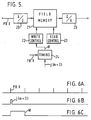
- Figure 5 is a block diagram of the video tape recorder reproduction signal processing circuit embodying the present invention
- Figure 6 is a timing chart for explaining the operation of the processing circuit.
- the reproduced video signal PB.E from the demodulator 7 ( Figure 1) is supplied to an analog to digital converter 20, the output of which is supplied to a field memory 21 having a storage capacity of one field period.
- the field memory 21 is controlled by a write control circuit 22 and a read control circuit 23, by which read and write operations are carried out in parallel.
- a timing circuit 24 in Figure 5 receives this signal, and a write command pulse W shown in Figure 6C with a duration corresponding to one field period of the reproduced vertical sync. signal is produced.
- the pulse W is supplied to the write control circuit 22 which forms address information supplied to the field memory 21.
- a reproduced video signal without ringing is written into the field memory 21.
- the contents of the field memory 21 are read out repetitively in response to address information supplied by the read control circuit 23.
- the output of the field memory 21 is supplied to a digital to analog converter 25, and transformed into the analog picture signal.
- the field memory 21 is written in (refreshed) once every four frames, and a slow motion reproduction picture without ringing is obtained. It should be noted that when the field memory 21 is not used, that is in previously proposed systems, one track is traced three times before switching to the next track for the one-third speed reproduction.
- the invention can also be applied to a jump control system in which a head jump or flyback is carried out when the voltage applied to the bimorph plate 2 has reached a certain level so that the bimorph plate 2 is not bent beyond a maximum allowable amount.
- the head output is written into the field memory 21 only when the head jump signal is absent (no jumping), and the memory contents are read out repetitively to produce a slow-motion picture or a still picture. Consequently, even if a residual vibration of the head position control means caused by the sharp jump voltage applied thereto during a head jump generates a ringing in the reproduced output, only the reproduced output without ringing is extracted, whereby a very high quality slow-motion picture or still picture can be formed.
Abstract
Description
- This invention relates to video signal reproducing apparatus.
- Reproducing apparatus of the type in which the position of a rotary head is controlled in the traverse direction relative to skew recording tracks formed on a magnetic tape can operate to correct an angular difference between a recording track and the scanning path of a reproducing head when reproducing at other than the normal forward speed. This occurs in modes such as slow-motion, still-picture, fast- motion and reverse-motion, in which the tape speed on reproducing is different from the tape speed on recording.
- In slow-motion reproduction, there is multiple tracing in which the same track is traced several times. For such multiple tracing, the reproducing head must be moved quickly by one track pitch between the end and the beginning of the track. This is because the tape is wound askew at a predetermined angle around the peripheral surface of the rotary head drum, the end of each track being displaced by one track pitch in the axial direction of the drum relative to the beginning of that track, when the tape is stationary.
- To achieve the required flyback or jump of the reproducing head, a sharp voltage pulse is applied to an electromechanical transducer which controls the head position. However, due to the transient response of the transducer, a ringing or vibration occurs in the reproduced video signal as the trace starts, and this sometimes results in degradation of the reproduced picture.
- According to the present invention there is provided a video signal reproducing apparatus comprising:
- a head position control means for controlling the position of a rotary magnetc reproducing head in the traverse direction of a skew recorded track formed on a magnetic tape;
- a trace control circuit for supplying a jump signal to said head position control means which causes said magnetic head to jump to the beginning of a said track to be traced next on completion of each tracing;
- a memory for storing the output signal from said magnetic head corresponding to at least one said tracing; and
- a memory reading and writing control circuit for writing said head output signal into said memory only when said jump signal is absent during slow motion or still-picture reproduction, and for reading said stored head output out of said memory repetitively.
- The invention will now be described by way of example with reference to the accompanying drawings, in which:
- Figure 1 is a block diagram of a head position control system for a video tape recorder in which an embodiment of the invention can be used;
- Figure 2 is a block diagram of a trace control circuit shown in Figure 1;
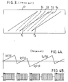
- Figure 3 is a diagram showing tracks (solid lines) and head scanning paths (dashed lines) during one-third speed reproduction;
- Figures 4A and 4B are waveforms showing the drive voltage to a bimorph plate shown in Figure 1, and a reproduced radio frequency output signal from a magnetic head;
- Figure 5 is a block diagram of a reproduced signal processing circuit; and
- Figure 6 is a timing chart of the operation of the circuit of Figure 5.
- Figure 1 is a block diagram of a head position control system for a video tape recorder of the single head type or of the type having an auxiliary head (sometimes called a 1.5 head type), in which an embodiment of the invention can be used.
- To a
rotary head drum 1 of the video tape recorder is secured abimorph plate 2, which is a lamination of two pieces of piezo-ceramic material. A rotarymagnetic head 3 is mounted on the free end of thebimorph plate 2, which is supplied with a sinusoidal wave of 500 Hz to 1 KHz from an integrating drive circuit 4, so that themagnetic head 3 is vibrated across a recording track on a magnetic tape (not shown). Consequently, the envelope of the reproduced radio frequency output signal derived from themagnetic head 3 undergoes amplitude modulation. - By detecting the correlation between the amplitude modulation component and the sinusoidal wave causing the head vibration, the displacement of the
magnetic head 3 relative to the track, that is the tracking error, can be detected. Thus, if the reproduced radio frequency output signal decreases as themagnetic head 3 swings in one direction across the track, it can be determined that themagnetic head 3 is moving away from the centre of the track in the direction of swing, and if the output signal increases, it can be determined that themagnetic head 3 is moving towards the centre of the track. - The output from the
magnetic head 3 is supplied to a tracking error detector circuit 5, so that the tracking error is detected based on the above-mentioned principle. The tracking error detector circuit 5 may, for example, be as disclosed in Japanese patent application 53/110174 (GB-A-2030346). An arangement may be provided such that the amplitude modulation component of the envelope of the reproduced radio frequency output signal is extracted, and then the modulation component and the output of a strain gauge 6 mounted on thebimorph plate 2 for sensing the head vibration are multiplied together, so that the magnitude and the polarity of the tracking error are determined. - The output of the tracking error detector circuit 5 is supplied to the integrating drive circuit 4, where the output is superimposed on the head vibration signal, which is then supplied to the
bimorph plate 2 with a certain amplitude. The tracking error detecting circuit 5 may alternatively be arranged such that reference signals with different frequencies are recorded alternately or sequentially in each track, and the head position relative to the track, that is the tracking error, is determined based on the ratio of the reproduced level of these reference signals when the magnetic tape is reproduced. - The output of the
magnetic head 3 is supplied to a demodulator 7 and demodulated to derive a reproduced video signal PB.E which is supplied to the video tape recorder processing circuit (not shown). The output of the demodulator 7 is also supplied to atrace control circuit 8 which produces a skew correction signal k for correcting the deviation of the head scanning path from the track for varied speed reproduction, and a head jump signal j for bringing themagnetic head 3, on completion of tracking of each track to the beginning of the track next to be traced. - The
trace control circuit 8 may be as disclosed in Japanese patent application 53/110174 mentioned above, in which the skew correction signal k and the jump signal j are formed on the basis of the varying portion of the relative moving speed between themagnetic head 3 and the magnetic tape using the varied speed reproduced sync. signal. - Figure 2 is a block diagram of the
trace control circuit 8 in Figure 1. A horizontal sync. signal PB.H in the reproduced video signal PB.E is supplied to a frequency variation detector circuit 11, and the signal corresponding to the tape speed (with a speed multiplication ratio of n) is detected. For example, in double speed reproduction (n=2) of a 525 line television signal, the period of the reproduced horizontal sync. signal varies by the amount AH=+a/262.5 (where α is the horizontal sync. alignment value of the track), and the speed multiplication ratio n can be obtained by measuring the horizontal period with a counter. - The output of the frequency variation detector circuit 11 is supplied to an
arithmatic operation circuit 12 which produces the skew correction signal k corresponding to the value of n-1. In double speed reproduction, for example, the skew of the head scanning path relative to the track differs by one track pitch (corresponding to n-1) from the case of normal speed reproduction; thus the difference of skew is corrected by applying the one track pitch skew voltage to thebimorph plate 2. The skew correction signal k from thearithmetic operation circuit 12 is supplied to the integrating drive circuit 4 in Figure 1, is integrated and amplified with a predetermined time constant and gain, and is then supplied to thebimorph plate 2. - The speed multiplication ratio signal n is supplied to an m
value detector circuit 13. This m is an integer with a relation to the n: - m is less than n is less than m+
- Selection of the m jump or the m+1 jump is carried out based on the output of a
jump determination circuit 15. The jump condition can be determined based on the output Δφ from a phasedifference detector circuit 16 which provides the phase difference between a reproduced vertical sync. signal PB.V and a reference vertical sync. signal Ref. V. In double speed reproduction, for example, the reproduced horizontal period varies by the amount ΔH=+α/262.5 as mentioned previously, and therefore the reproduced vertical sync. signal PB.V will vary in its phase (or period) by the amount ΔH=+α. In general, the reproduction phase at a specific point on the track varies by (n―1)α for one tracing, due to the movement of the magnetic tape relative to themagnetic head 3 in n times speed reproduction. On the other hand, jumping of themagnetic head 3 by one track pitch causes the reproduction phase to vary by +α. In general, an m―1 jump causes a ―(m―1)α phase variation, and an m jump causes a mα phase variation. Accordingly, the amount of phase variation on the specific point of the track during two consecutive tracings is expressed as the sum of the variation due to the tape movement and the variation due to the head jump as follows: - Δ = (n-m)α is greater than or equal to 0, or


- φ+Δ is greater than or less than +α/2
- In Figure 2 the above determination is carried out by the
jump determination circuit 15 based on the values of the n, m and Δφ, and the selection switch 14 is switched in response to the output in the manner indicated. - Figure 3 is a chart showing tracks T, Tt12, ... (solid lines) and head scanning paths S1, S2, ... (dashed lines) on a magnetic tape 17 in the plus one-third speed (n=0.33) reproduction. Figure 4 is a set of waveform charts showing the bimorph drive voltage and the reproduced radio frequency output.
- As shown in Figure 3, head scanning paths S1, S2, ... have a skew error or 1-1/3=2/3 relative to tracks T1, T2, ... In order to correct the skew error, a triangular skew correction voltage as shown in Figure 4A is produced by the integrating drive circuit 4 in response to the skew correction signal k (that is n-1 ) from the
trace control circuit 8, and supplied to thebimorph plate 2. At the point when the path S1 for the track T1 is complete, themagnetic head 3 is located at the beginning of the track T2, and in this case the head jump signal j of m=―1 pitch is produced by thetrace control circuit 8. The jump signal j is integrated to produce a sharp jump voltage as shown in Figure 4A, and it is applied to thebimorph plate 2 so that themagnetic head 3 is returned or flown back to the beginning of the track T1. - Similarly, for the traces S2 and S3, the same track T1 is scanned in alternative repetition for skew correction and jumping. For the fourth trace S4, the
jump determination circuit 15 of Figure 2 produces a jump signal j corresponding to m=O, so that the scanning track is switched to T2 for tracing rather than jumping, as shown in Figure 4A. This operation is repeated and a slow-motion picture at one-third speed is obtained. - At head jump causes the
bimorph plate 2 to have applied to it a sharp jump voltage, creating a ringing in the reproduced radio frequency output signal from themagnetic head 3 due to the transient vibration of thebimorph plate 2 as shown in Figure 4B. This ringing causes a significant degradation of the reproduced picture, and in this embodiment, a slow-motion picture is produced by repeating the reproduced radio frequency signal without ringing, this being obtained in the trace S4 in Figure 4A when the head jump does not occur. - Figure 5 is a block diagram of the video tape recorder reproduction signal processing circuit embodying the present invention, and Figure 6 is a timing chart for explaining the operation of the processing circuit.
- The reproduced video signal PB.E from the demodulator 7 (Figure 1) is supplied to an analog to
digital converter 20, the output of which is supplied to afield memory 21 having a storage capacity of one field period. Thefield memory 21 is controlled by awrite control circuit 22 and aread control circuit 23, by which read and write operations are carried out in parallel. - When a jump signal for m=O as shown in Figure 6, where head jump does not take place, but only the track scanned is altered, is produced by the trace control circuit 8 (Figure 1), a
timing circuit 24 in Figure 5 receives this signal, and a write command pulse W shown in Figure 6C with a duration corresponding to one field period of the reproduced vertical sync. signal is produced. The pulse W is supplied to thewrite control circuit 22 which forms address information supplied to thefield memory 21. As a result, a reproduced video signal without ringing is written into thefield memory 21. The contents of thefield memory 21 are read out repetitively in response to address information supplied by theread control circuit 23. The output of thefield memory 21 is supplied to a digital toanalog converter 25, and transformed into the analog picture signal. - For the one-third speed reproduction, the
field memory 21 is written in (refreshed) once every four frames, and a slow motion reproduction picture without ringing is obtained. It should be noted that when thefield memory 21 is not used, that is in previously proposed systems, one track is traced three times before switching to the next track for the one-third speed reproduction. - In addition to the foregoing embodiment, the invention can also be applied to a jump control system in which a head jump or flyback is carried out when the voltage applied to the
bimorph plate 2 has reached a certain level so that thebimorph plate 2 is not bent beyond a maximum allowable amount. - For reproducing a still picture, the magnetic tape 17 continues to be transported even after the still picture command key has been operated, until the
field memory 21 has been written- in, the same as described above when the jump signal with m=0 is detected. Then the magnetic tape 17 is stopped and the contents of thefield memory 21 are read out repetitively to form a still picture. - Thus, as described above, the head output is written into the
field memory 21 only when the head jump signal is absent (no jumping), and the memory contents are read out repetitively to produce a slow-motion picture or a still picture. Consequently, even if a residual vibration of the head position control means caused by the sharp jump voltage applied thereto during a head jump generates a ringing in the reproduced output, only the reproduced output without ringing is extracted, whereby a very high quality slow-motion picture or still picture can be formed.
and an arbitrary n times speed reproduction is achieved by combination of m+ times speed reproduction and m times speed reproduction. For example, when treble speed reproduction and double speed reproduction are carried out alternately, an averaged 2.5-times speed reproduction can be performed. For m+1 times speed reproduction, a head jump by m track pitches is required on each completion of tracking, and for m time speed reproduction, a head jump by m-1 track pitches is required. This is because the beginning and the end of a track are located one track pitch apart. The m
φ is greater than or less than ―nα+(m+
Claims (6)
and a phase difference detector circuit (16) for selecting which of said values of said jump signal (j) is to be supplied to said head position control means (4) in dependence on the phase difference between a vertical sync. signal in said head output signal and a reference vertical sync. signal.
Priority Applications (1)
| Application Number | Priority Date | Filing Date | Title |
|---|---|---|---|
| AT81304942T ATE6114T1 (en) | 1980-11-07 | 1981-10-21 | PLAYBACK DEVICE FOR VIDEO SIGNALS. |
Applications Claiming Priority (2)
| Application Number | Priority Date | Filing Date | Title |
|---|---|---|---|
| JP157267/80 | 1980-11-07 | ||
| JP55157267A JPS5780880A (en) | 1980-11-07 | 1980-11-07 | Video signal reproducing device |
Publications (2)
| Publication Number | Publication Date |
|---|---|
| EP0051938A1 EP0051938A1 (en) | 1982-05-19 |
| EP0051938B1 true EP0051938B1 (en) | 1984-02-01 |
Family
ID=15645915
Family Applications (1)
| Application Number | Title | Priority Date | Filing Date |
|---|---|---|---|
| EP81304942A Expired EP0051938B1 (en) | 1980-11-07 | 1981-10-21 | Video signal reproducing apparatus |
Country Status (6)
| Country | Link |
|---|---|
| US (1) | US4445145A (en) |
| EP (1) | EP0051938B1 (en) |
| JP (1) | JPS5780880A (en) |
| AT (1) | ATE6114T1 (en) |
| CA (1) | CA1183944A (en) |
| DE (1) | DE3162133D1 (en) |
Families Citing this family (17)
| Publication number | Priority date | Publication date | Assignee | Title |
|---|---|---|---|---|
| JPS5783978A (en) * | 1980-11-12 | 1982-05-26 | Sony Corp | Video signal recorder and reproducer |
| JPS59178882A (en) * | 1983-03-29 | 1984-10-11 | Sharp Corp | Reproducing system of video tape recorder |
| JPS59191126A (en) * | 1983-04-14 | 1984-10-30 | Victor Co Of Japan Ltd | Device for controlling position of video head |
| JPS60117884A (en) * | 1983-11-29 | 1985-06-25 | Mitsubishi Electric Corp | Magnetic picture recording and reproducing device |
| JPS60261267A (en) * | 1984-06-07 | 1985-12-24 | Mitsubishi Electric Corp | Magnetic recording and reproducing device |
| JPH0650911B2 (en) * | 1984-10-26 | 1994-06-29 | ソニー株式会社 | Playback video signal processor |
| US4591931A (en) * | 1985-04-05 | 1986-05-27 | Eastman Kodak Company | Playback apparatus |
| DE3524128A1 (en) * | 1985-07-05 | 1987-01-08 | Thomson Brandt Gmbh | METHOD AND / OR DEVICE FOR PRODUCING STILL IMAGES |
| JPH0732479B2 (en) * | 1985-09-25 | 1995-04-10 | 株式会社東芝 | Image memory controller |
| JPH07123299B2 (en) * | 1985-10-18 | 1995-12-25 | 株式会社東芝 | Video tape recorder playback device |
| US4672475A (en) * | 1986-04-02 | 1987-06-09 | Matsushita Electric Industrial Co., Ltd. | Portable video tape recorder having a vibration detector |
| US4870510A (en) * | 1986-06-23 | 1989-09-26 | Canon Kabushiki Kaisha | Video signal reproducing apparatus using memory |
| US5179477A (en) * | 1989-01-21 | 1993-01-12 | Mitsubishi Denki Kabushiki | Video tape recorder |
| US5163162A (en) * | 1990-11-14 | 1992-11-10 | Ibm Corporation | System and method for data recovery in multiple head assembly storage devices |
| WO1994011991A1 (en) * | 1992-11-16 | 1994-05-26 | Ampex Systems Corporation | Tape format for recording digital audio video and audio signals |
| KR940016151A (en) * | 1992-12-30 | 1994-07-22 | 김주용 | Loop playback system for digital audio |
| KR100207621B1 (en) * | 1993-11-30 | 1999-07-15 | 윤종용 | Skew compensation apparatus of video tape recorder |
Family Cites Families (9)
| Publication number | Priority date | Publication date | Assignee | Title |
|---|---|---|---|---|
| GB1560023A (en) * | 1976-10-05 | 1980-01-30 | Sony Corp | Automatic magnetic-head scan tracking arrangements |
| DE2645747C2 (en) * | 1976-10-09 | 1984-02-16 | Robert Bosch Gmbh, 7000 Stuttgart | Method for reproducing individual images from television signals recorded on tape-shaped carriers |
| DE2725365C2 (en) * | 1977-06-04 | 1984-09-06 | Robert Bosch Gmbh, 7000 Stuttgart | Method for reproducing video signals stored on magnetic tape at a tape speed which differs from the tape speed during recording, and circuit arrangement therefor |
| FR2416607B1 (en) * | 1978-02-02 | 1986-08-01 | Indep Broadcasting Authority | DIGITAL TYPE TELEVISION SYSTEM AND METHOD |
| US4215362A (en) * | 1978-03-23 | 1980-07-29 | Ampex Corporation | Track selection method and apparatus |
| JPS54138324A (en) * | 1978-04-19 | 1979-10-26 | Sony Corp | Magnetic recording and reproducing unit |
| JPS5538649A (en) * | 1978-09-07 | 1980-03-18 | Sony Corp | Tracking unit of magnetic head |
| DE2841728C2 (en) * | 1978-09-26 | 1984-08-09 | Robert Bosch Gmbh, 7000 Stuttgart | Method and circuit arrangement for reproducing a video signal stored on magnetic tape at variable speed |
| US4389678A (en) * | 1979-10-05 | 1983-06-21 | Nippon Electric Co., Ltd. | Digital time-base corrector for special motion reproduction by helical-scan VTR |
-
1980
- 1980-11-07 JP JP55157267A patent/JPS5780880A/en active Granted
-
1981
- 1981-10-21 AT AT81304942T patent/ATE6114T1/en not_active IP Right Cessation
- 1981-10-21 DE DE8181304942T patent/DE3162133D1/en not_active Expired
- 1981-10-21 EP EP81304942A patent/EP0051938B1/en not_active Expired
- 1981-10-30 CA CA000389094A patent/CA1183944A/en not_active Expired
- 1981-11-03 US US06/317,906 patent/US4445145A/en not_active Expired - Lifetime
Also Published As
| Publication number | Publication date |
|---|---|
| JPS5780880A (en) | 1982-05-20 |
| ATE6114T1 (en) | 1984-02-15 |
| JPS6349956B2 (en) | 1988-10-06 |
| CA1183944A (en) | 1985-03-12 |
| DE3162133D1 (en) | 1984-03-08 |
| EP0051938A1 (en) | 1982-05-19 |
| US4445145A (en) | 1984-04-24 |
Similar Documents
| Publication | Publication Date | Title |
|---|---|---|
| EP0051938B1 (en) | Video signal reproducing apparatus | |
| US4410918A (en) | Helical scan VTR with deflectable head | |
| US4558376A (en) | Method and system of reproduction of magnetically recorded video signals at speeds differing from recording speed | |
| US4229773A (en) | Video signal recording system with automatic head positioning | |
| JP2584006B2 (en) | Magnetic recording / reproducing device | |
| US4549234A (en) | Method and apparatus for tracking control | |
| US4167762A (en) | Open loop servo-system for accurate tracking in a video signal reproducing apparatus | |
| US4470079A (en) | Tracking control system in a magnetic recording and reproducing apparatus | |
| US4426665A (en) | Automatic track following feature for helical video recorder | |
| EP0037738B1 (en) | Automatic track following feature for helical video recorder | |
| US4393416A (en) | Tracking system for a videotape recorder | |
| EP0227468B1 (en) | Recording and/or reproducing apparatus | |
| US4438463A (en) | Tracking control system | |
| US4656529A (en) | Video signal recording apparatus | |
| US4445146A (en) | Digital tracking control system for video tape reproducing apparatus | |
| JPS6412007B2 (en) | ||
| EP0392789B1 (en) | Tracking control device for a magnetic recording and reproducing apparatus | |
| US4393417A (en) | Tracking system | |
| US4549235A (en) | Apparatus for reproducing video signals | |
| JPS6341470B2 (en) | ||
| US5589997A (en) | Tracking control method and apparatus for video recorder which adds a combined first and second tracking error signal to the next tracking error signal | |
| JPS58154985A (en) | Helical scanning type video tape recorder | |
| EP0357352B1 (en) | Video signal recording/reproducing apparatus | |
| US4698699A (en) | Head positioning signal generating apparatus with signal duration control | |
| US5402279A (en) | Tracking apparatus for helical scan video tape recorders |
Legal Events
| Date | Code | Title | Description |
|---|---|---|---|
| PUAI | Public reference made under article 153(3) epc to a published international application that has entered the european phase |
Free format text: ORIGINAL CODE: 0009012 |
|
| 17P | Request for examination filed |
Effective date: 19811027 |
|
| AK | Designated contracting states |
Designated state(s): AT DE FR GB NL |
|
| GRAA | (expected) grant |
Free format text: ORIGINAL CODE: 0009210 |
|
| AK | Designated contracting states |
Designated state(s): AT DE FR GB NL |
|
| REF | Corresponds to: |
Ref document number: 6114 Country of ref document: AT Date of ref document: 19840215 Kind code of ref document: T |
|
| REF | Corresponds to: |
Ref document number: 3162133 Country of ref document: DE Date of ref document: 19840308 |
|
| ET | Fr: translation filed | ||
| PLBE | No opposition filed within time limit |
Free format text: ORIGINAL CODE: 0009261 |
|
| STAA | Information on the status of an ep patent application or granted ep patent |
Free format text: STATUS: NO OPPOSITION FILED WITHIN TIME LIMIT |
|
| 26N | No opposition filed | ||
| PGFP | Annual fee paid to national office [announced via postgrant information from national office to epo] |
Ref country code: FR Payment date: 19941011 Year of fee payment: 14 Ref country code: GB Payment date: 19941011 Year of fee payment: 14 |
|
| PGFP | Annual fee paid to national office [announced via postgrant information from national office to epo] |
Ref country code: DE Payment date: 19941021 Year of fee payment: 14 |
|
| PGFP | Annual fee paid to national office [announced via postgrant information from national office to epo] |
Ref country code: NL Payment date: 19941031 Year of fee payment: 14 |
|
| PG25 | Lapsed in a contracting state [announced via postgrant information from national office to epo] |
Ref country code: GB Effective date: 19951021 |
|
| PG25 | Lapsed in a contracting state [announced via postgrant information from national office to epo] |
Ref country code: NL Effective date: 19960501 |
|
| GBPC | Gb: european patent ceased through non-payment of renewal fee |
Effective date: 19951021 |
|
| PG25 | Lapsed in a contracting state [announced via postgrant information from national office to epo] |
Ref country code: FR Effective date: 19960628 |
|
| PG25 | Lapsed in a contracting state [announced via postgrant information from national office to epo] |
Ref country code: DE Effective date: 19960702 |
|
| NLV4 | Nl: lapsed or anulled due to non-payment of the annual fee |
Effective date: 19960501 |
|
| REG | Reference to a national code |
Ref country code: FR Ref legal event code: ST |
|
| PGFP | Annual fee paid to national office [announced via postgrant information from national office to epo] |
Ref country code: AT Payment date: 19971016 Year of fee payment: 17 |
|
| PG25 | Lapsed in a contracting state [announced via postgrant information from national office to epo] |
Ref country code: AT Free format text: LAPSE BECAUSE OF NON-PAYMENT OF DUE FEES Effective date: 19981021 |