EP0050610B1 - Real-time performance monitoring of gas turbine engines - Google Patents
Real-time performance monitoring of gas turbine engines Download PDFInfo
- Publication number
- EP0050610B1 EP0050610B1 EP19800900964 EP80900964A EP0050610B1 EP 0050610 B1 EP0050610 B1 EP 0050610B1 EP 19800900964 EP19800900964 EP 19800900964 EP 80900964 A EP80900964 A EP 80900964A EP 0050610 B1 EP0050610 B1 EP 0050610B1
- Authority
- EP
- European Patent Office
- Prior art keywords
- monitored
- engine
- coefficients
- performance parameter
- signals
- Prior art date
- Legal status (The legal status is an assumption and is not a legal conclusion. Google has not performed a legal analysis and makes no representation as to the accuracy of the status listed.)
- Expired
Links
- 238000012544 monitoring process Methods 0.000 title claims abstract description 91
- 238000001914 filtration Methods 0.000 claims abstract description 39
- 238000012545 processing Methods 0.000 claims abstract description 15
- 230000002123 temporal effect Effects 0.000 claims abstract description 10
- 230000036962 time dependent Effects 0.000 claims abstract description 10
- 230000001419 dependent effect Effects 0.000 claims description 140
- 239000011159 matrix material Substances 0.000 claims description 100
- 238000004088 simulation Methods 0.000 claims description 76
- 239000013598 vector Substances 0.000 claims description 46
- 238000000034 method Methods 0.000 claims description 25
- 238000009434 installation Methods 0.000 claims description 17
- 230000014509 gene expression Effects 0.000 claims description 14
- 230000007423 decrease Effects 0.000 claims description 3
- 238000001514 detection method Methods 0.000 claims description 3
- 230000000737 periodic effect Effects 0.000 claims description 2
- 238000003491 array Methods 0.000 claims 2
- 238000012986 modification Methods 0.000 claims 2
- 230000004048 modification Effects 0.000 claims 2
- 230000000694 effects Effects 0.000 abstract description 12
- 238000004590 computer program Methods 0.000 description 45
- 239000007789 gas Substances 0.000 description 36
- 239000003570 air Substances 0.000 description 21
- 230000000875 corresponding effect Effects 0.000 description 21
- 230000006866 deterioration Effects 0.000 description 14
- 238000004458 analytical method Methods 0.000 description 12
- 238000012423 maintenance Methods 0.000 description 11
- 238000005070 sampling Methods 0.000 description 11
- 238000010586 diagram Methods 0.000 description 10
- 230000006870 function Effects 0.000 description 10
- 238000012417 linear regression Methods 0.000 description 6
- 239000000446 fuel Substances 0.000 description 5
- 230000007257 malfunction Effects 0.000 description 5
- 238000004519 manufacturing process Methods 0.000 description 5
- 238000012360 testing method Methods 0.000 description 5
- 230000001052 transient effect Effects 0.000 description 5
- 230000003190 augmentative effect Effects 0.000 description 4
- 239000000654 additive Substances 0.000 description 3
- 230000000996 additive effect Effects 0.000 description 3
- 238000004364 calculation method Methods 0.000 description 3
- 230000008859 change Effects 0.000 description 3
- 238000002485 combustion reaction Methods 0.000 description 3
- 238000010606 normalization Methods 0.000 description 3
- 238000007619 statistical method Methods 0.000 description 3
- 230000003750 conditioning effect Effects 0.000 description 2
- 230000002596 correlated effect Effects 0.000 description 2
- 238000013461 design Methods 0.000 description 2
- 238000011156 evaluation Methods 0.000 description 2
- 230000006872 improvement Effects 0.000 description 2
- 230000003252 repetitive effect Effects 0.000 description 2
- 208000034530 PLAA-associated neurodevelopmental disease Diseases 0.000 description 1
- 230000002159 abnormal effect Effects 0.000 description 1
- 230000001133 acceleration Effects 0.000 description 1
- 230000003213 activating effect Effects 0.000 description 1
- 230000003044 adaptive effect Effects 0.000 description 1
- 239000012080 ambient air Substances 0.000 description 1
- 238000013459 approach Methods 0.000 description 1
- 230000006399 behavior Effects 0.000 description 1
- 230000000903 blocking effect Effects 0.000 description 1
- 239000000567 combustion gas Substances 0.000 description 1
- 230000000295 complement effect Effects 0.000 description 1
- 230000001143 conditioned effect Effects 0.000 description 1
- 230000001276 controlling effect Effects 0.000 description 1
- 230000001934 delay Effects 0.000 description 1
- 230000003111 delayed effect Effects 0.000 description 1
- 229910003460 diamond Inorganic materials 0.000 description 1
- 239000010432 diamond Substances 0.000 description 1
- 239000006185 dispersion Substances 0.000 description 1
- 230000010006 flight Effects 0.000 description 1
- 239000012530 fluid Substances 0.000 description 1
- 230000009474 immediate action Effects 0.000 description 1
- 230000000977 initiatory effect Effects 0.000 description 1
- 238000005259 measurement Methods 0.000 description 1
- 238000011022 operating instruction Methods 0.000 description 1
- 230000035935 pregnancy Effects 0.000 description 1
- 230000002028 premature Effects 0.000 description 1
- 238000000611 regression analysis Methods 0.000 description 1
- 230000000717 retained effect Effects 0.000 description 1
- 230000001502 supplementing effect Effects 0.000 description 1
- 230000009466 transformation Effects 0.000 description 1
Images



Classifications
-
- G—PHYSICS
- G05—CONTROLLING; REGULATING
- G05B—CONTROL OR REGULATING SYSTEMS IN GENERAL; FUNCTIONAL ELEMENTS OF SUCH SYSTEMS; MONITORING OR TESTING ARRANGEMENTS FOR SUCH SYSTEMS OR ELEMENTS
- G05B23/00—Testing or monitoring of control systems or parts thereof
- G05B23/02—Electric testing or monitoring
- G05B23/0205—Electric testing or monitoring by means of a monitoring system capable of detecting and responding to faults
- G05B23/0218—Electric testing or monitoring by means of a monitoring system capable of detecting and responding to faults characterised by the fault detection method dealing with either existing or incipient faults
- G05B23/0243—Electric testing or monitoring by means of a monitoring system capable of detecting and responding to faults characterised by the fault detection method dealing with either existing or incipient faults model based detection method, e.g. first-principles knowledge model
-
- G—PHYSICS
- G07—CHECKING-DEVICES
- G07C—TIME OR ATTENDANCE REGISTERS; REGISTERING OR INDICATING THE WORKING OF MACHINES; GENERATING RANDOM NUMBERS; VOTING OR LOTTERY APPARATUS; ARRANGEMENTS, SYSTEMS OR APPARATUS FOR CHECKING NOT PROVIDED FOR ELSEWHERE
- G07C3/00—Registering or indicating the condition or the working of machines or other apparatus, other than vehicles
Definitions
- This invention relates to a system for analyzing the performance of a gas turbine engine. More particularly, this invention relates to a system for monitoring a gas turbine engine wherein various engine performance parameters are sensed and compared with predicted values of the same parameters to supply deviation or error signals indicative of the condition of the engine.
- the ground based systems include equipment on the aircraft to periodically record the values of various engine performance parameters during periods of aircraft operation in which the monitored engine is operated under predetermined conditions and include a ground based monitoring station which generally utilizes a large scale digital computer.
- recorded engine performance data is either transmitted to the ground based monitoring station or, more typically, stored on magnetic tape or other media within the aircraft for delivery to the ground station at a later convenient time.
- the engine data is received at the ground station, it is generally "conditioned" by filtering techniques to remove a substantial portion of the noise content and to normalize the data so that it is amenable to processing within the particular computer and analysis routine that is employed. After such conditioning and normalization, the data is stored within a data bank for later computer processing.
- this processing is performed on a periodic basis to determine the temporal or trend characteristics of the monitored engine parameters, which trend information is useful in supplementing periodical overhaul policies to prevent premature removal of an engine. Additionally, when an engine fails in service, the previously recorded engine performance data can be processed within the computer to aid in determining the cause of engine failure and hence ensure that adequate overhaul procedures are followed before the engine is returned to service.
- ground based engine monitoring systems have both diagnostic and prognostic capabilities, several disadvantages and drawbacks are presented.
- the analysis of gas turbine engine performance is not effected as the engine operates (i.e., in "real- time” or "on-line") but, because of delays encountered in recording the engine data, transmitting it to the ground station and analyzing the data within the computer, the diagnostic and prognostic capabilities of the system are limited.
- such "after-the-fact” analysis may not be readily available when an engine must be removed and quickly restored to service.
- after-the-fact analysis does not provide the flight crew with current engine performance data and in-flight procedures which could prevent serious engine damage cannot be initiated.
- the costs associated with operating such a system are relatively high both in terms of the required investment in equipment and the labor costs involved in operating and maintaining such a system.
- a major drawback of this known method lies in the fact that although gas turbine engines are manufactured and refurbished in accordance with strict dimensional tolerances, the actual performance parameters of engines within a particular type deviate from theoretical or nominal values by an amount that is significant with respect to the accuracy requirements of a monitoring system which will detect minute changes in engine performance parameters to thereby indicate engine deterioration before serious engine failure occurs.
- most prior art gas turbine engine monitoring systems which rely on a theoretical engine model are inherently limited in monitoring accuracy.
- Systems such as those disclosed by the known specification at least partially overcome this limitation by utilizing previously recorded data that is obtained from the engine being monitored as the engine monitoring reference or base line.
- the object of the invention is to provide a monitoring system for gas turbine engines of wihch system the accuracy does not depend on theoretical models nor on manufacturing tolerances, the accuracy nevertheless being sufficient for detecting minute changes in engine performance characteristics.
- Another object of the invention is to provide a monitoring system for gas turbine engines which is immune to sensor inaccuracies and to signal noise.
- US-A-3,731,070 describes a monitoring system for a gas turbine engine which system comprises means to compute the rate of change of several different thermodynamically independent variables.
- this system still suffers from the drawbacks of insufficient accuracy due to sensor inaccuracies and signal noise, and of dependencies on theoretical models and their limitations.
- US-A-3,750,465 describes a steady state detector, which serves the purpose of blocking out spurious signals.
- system sensors detect the current value of engine operating data, including various engine performance parameters, air data signals and/or engine control signals, and supply signals representative of this data to a digital processor unit that utilizes these signals (and certain functions thereof in predicting current values of one or more engine parameters that are indicative of deterioration in engine performance.
- engine performance parameters are referred to hereinafter as dependent performance parameters of variables and the engine operating data (or signals representative thereof) that are utilized in the prediction of these dependent performance parameters are hereinafter referred to as independent performance parameters or variables; such terminology being with reference to the parametric interrelationship between these parameters within the methe- matical description of the electronic simulation or modeling that is utilized in the practice of this invention.
- the electronic simulation or modeling that is achieved by the digital processor can be represented methematically by the matrix equation:
- Y CX+E, where Y is a column vector comprising the predicted dependent engine performance parameters, X is a column vector comprising the independent performance parameters, C is a matrix of scalar coefficients, and E is a column vector comprising scalar elements which represent modeling inaccuracies.
- Y and E are column vectors each having n elements, X is a column vector having m elements and the coefficient matrix C includes m elements in each row and n elements in each column.
- such electronic simulation or modeling does not rely only on those sets of dependent and independent engine parameters which, through appropriate coefficients, are known in the art to parametrically describe the steady state thermodynamic gas generator characteristics of the type of engine being monitored.
- a set of independent engine parameters ( Xi ) for estimating the values of a set of desired dependent engine parameters is determined from engine performance data of the particular type of engine to be monitored (e.g., a Pratt-Whitney JT8 or JT9 type engine, of even more generally, any high bypass, twin spool gas turbine engine), by linear regression analysis of such engine performance data. It has been found that, when the independent engine parameters are selected in this manner, such parameters are generic to, and uniquely characterize, the type of engine being monitored whereas the coefficients (c) distinguish a particular engine being monitored from others of the same type to thereby account for normal engine manufacturing and installation tolerances.
- engine performance data e.g., a Pratt-Whitney JT8 or JT9 type engine, of even more generally, any high bypass, twin spool gas turbine engine
- the selected set of independent engine parameters provides valid and accurate prediction of the dependent engine parameters over a corresponding range of operating conditions. Accordingly in the practice of this invention, system accuracy is maintained over a wide range of engine operating conditions which can include the entire range of steady state operating conditions that are encountered in the normal operation of the aircraft which utilizes the monitored engine.
- the system is operable in an in-flight calibration mode wherein digital signal filtering is employed to determine values of the coefficients c that are appropriate to the particular engine being monitored. These coefficients are stored within memory registers and utilized until the engine being monitored is replaced or the monitoring system or engine is otherwise modified in a manner which requires new coefficient values in order to restore and maintain the desired system accuracy. More specifically, in each disclosed embodiment of the invention, recursive digital filtering of the type commonly identified as Kalman filtering is implemented within the digital processor to provide the desired coefficients.
- the digital processor estimates the current value of each monitored dependent engine parameter based on current values of the coefficients c and the current values of the independent engine parameters x; determines the error between the estimated and actual values of the monitored dependent engine parameters y; and, updates the values of each stored coefficient c such that the estimation error decreases.
- the data processor continues to refine the values of the above-described coefficients until a desired prediction accuracy is achieved. Further, since the calibration mode can be effected in flight with the monitored engine being operated under normal flight conditions, the final coefficient values are not related to either a hypothetical nominal engine and/or to an engine operating state that does not represent actual flight conditions.
- signals representative of the estimated value of each dependent engine performance parameter are supplied to a difference unit which can be realized within the digital processor unit or by other conventional electronic circuitry.
- the signals are compared with signals representative of the actual current value of each of the dependent engine parameters (provided by a set of sensors mounted to or within the engine being monitored), to supply deviation signals that represent the difference between the estimated and actual values of each dependent performance parameter.
- These deviation signals are coupled to monitoring logic which combines the signals to detect a fault within the digital processor, the system sensors, or the gas turbine engine.
- the deviation signals are utilized within the digital processor to supply signals which estimate the temporal characteristics or trends associated with any or all of the monitored dependent engine performance parameters.
- This trend information is of considerable prognostic value to the flight crew and to maintenance personnel in that such information allows estimation of the time at which the monitored engine will require overhaul, maintenance activity, or procedural changes relative to the manner in which the engine is operated.
- the trend signals provided in accordance with this invention are indicative of the rate at which deterioration in engine performance is occurring.
- the trend signals are supplied by augmenting the electronic simulation or modeling arrangement of the data processor to include time dependent terms that are capable of characterizing the time varying drift in the values of critical engine performance parameters, i.e., the monitored dependent engine parameters, which changes in engine performance that are attributable to sources such as normal engine wear.
- operation of the electronic simulation or modeling of each dependent engine parameter can be represented by the mathematical expression where t is the length of time that the system has been monitoring that particular engine, r defines the order of the polynomial estimate being utilized to describe the time-dependent nature of the dependent variable y, and each coefficient b,,b,,...bq is a scalar quantity.
- recursive digital filtering is employed to supply signals representative of the trend coefficients b o , b"...,bq that are associated with each monitored dependent engine performance parameter every time the digital processor unit monitors the value of that particular engine parameter.
- Kalman filtering or estimation is utilized wherein the data processor uses the previously mentioned deviation signal (difference between the actual and estimated value of the dependent engine parameter) to determine the current values of the trend coefficients.
- current values of the trend coefficients reflect changes that occur in the monitored dependent engine parameters over the entire period in which the system is interconnected with the monitored engine installation. Accordingly, the trend coefficients are capable of characterizing relatively subtle (i.e., very slow) changes in engine performance.
- the signals which represent each of the trend coefficients are supplied to trend logic which utilizes combinatorial logic to provide an indication of prognostic information such as the estimated number of hours the engine can be operated prior to overhaul, go/no-go dispatchability of the aircraft and in-flight warning of a predicted imminent engine malfunction.
- the monitoring system of this invention can be structured in a variety of manners. For example, in embodiments wherein relatively few engine performance parameters need be monitored and the monitored dependent parameters can be characterized by relatively few independent engine parameters, an embodiment of this invention can utilize hard-wired arrangements of commercially available digital integrated circuits or discrete circuit components. On the other hand, in embodiments in which several dependent engine variables are to be monitored and/or several independent engine parameters are required to achieve the desired system accuracy, a programmable computer is advantageously employed to implement at least the digital filtering and performance parameter modeling.
- computers suitable for use in such embodiments not only include conventional airborne computers of the type that are programmed by conventional software techniques, but also include relatively small and simple computing devices such as those conventional integrated circuits commonly called microprocessors.
- microprocessor arrangement can be programmed by software techniques, hardwire connections, stored information such as read-only memory units (i.e., "firm-wire"), and various combinations thereof.
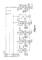
- Fig. 1 depicts a monitoring system of this invention arranged for monitoring the performance of a gas turbine engine of the high bypass twin spool variety (generally denoted by the numeral 10).
- a gas turbine engine is mounted within a nacelle or outer housing 12 which defines an air inlet duct 14 at the forward end of the engine 10.
- the air inlet duct 14 supplies airflow to allow pressure, low speed compressor or fan stage 18 which is journalled within the nacelle 12.
- a portion of the air supplied by the fan stage 18 is supplied to a high pressure, high speed compressor 22 and the remaining portion is exhausted rearwardly through an annular duct 24 which is formed between the outer housing 12 and an inner housing 26 that encloses the compressor 22 and other elements of the engine core.
- Fuel injected into the combustor assembly 27 by a series of nozzles (not shown in Fig. 1) is mixed with the compressed air and ignited within the combustor assembly 27.
- the hot combustion gases exiting the combustor assembly 27 drive a high pressure turbine stage 28 which, in turn, drives the high pressure compressor stage 22 through a shaft 30.
- a low pressure turbine stage 32 which is connected to the low pressure compressor stage 18 by a shaft 34 that passes coaxially through the shaft 30, is driven by the combustion products exiting the high pressure turbine stage 28.
- the exhaust nozzle 38 is an annular duct that is formed between the inner housing 26 and a rearwardly projecting tailcone 40.
- twin spool, high bypass gas turbine engines can include structure not diagrammatically set forth in the engine 10 of Fig. 1.
- such engines can be of the mixed flow variety wherein at least a portion of the fan bypass stream is not exited to the atmosphere through the duct 24, but flows rearwardly around the inner housing 26 and is mixed with the hot combustion products which exit the turbine state 32 to provide increased thrust and lower jet noise.
- the air inlet 14 and exhaust nozzle 38 can be of controllable or variable geometry to respectively permit control over the airflow entering the engine and the expansion characteristics of the hot combustion products.
- the hereinafter described monitoring system of this invention is not restricted to the particular type of engine 10 depicted in Fig.
- the performance monitoring system of this invention includes a number of sensors interconnected with the engine 10, sensors interconnected with control apparatus which determines the operating state of the engine 10, and conventional air data apparatus or appropriate sensors which supply signals representative of parameters such as aircraft speed and altitude. More specifically, in the arrangement of the invention depicted in Fig.
- PPA power level angle
- the signals supplied by the set of sensors 44, the PLA sensor 46 and the air data system 51 are coupled to a digital processor unit 52 and in particular to a portion of the data processor 52 which is identified in Fig. 1 as an engine parameter simulator 54.
- a digital processor unit 52 and in particular to a portion of the data processor 52 which is identified in Fig. 1 as an engine parameter simulator 54.
- analog-to-digital converters can be employed to provide appropriate digital signals to the digital processor 52.
- conventional digital-to-digital convertors can be employed.
- the signals supplied by the set of sensors 44, the PLA sensor 46, and the air data system 51 are utilized by the engine parameter simulator 54 to determine a set of signals y 1 , y 2 ,..., y n which represent the predicted or estimated values of a number of engine performance parameters.
- the estimated or predicted engine performance parameters (Y k ) are dependent variables and the functions of the sensed engine operating signals (x,) are independent variables.
- those engine performance parameters that are estimated or predicted by the electronic parameter simulator 54 will be referred to hereinafter as dependent performance parameters.
- those engine installation parameters and air data parameters utilized within the engine parameter simulator 54 to estimate the dependent performance parameters e.g., the signals denoted as s 1 , s 2 ,...,s P in Fig. 1
- the functions thereof which are denoted as x 1 , x 2 ,...,x m in the above mathematical expressions will be referred to as independent performance parameters.
- a particular engine parameter which is treated as a dependent performance parameter can also be utilized as an independent per-' formance parameter in predicting the value of another dependent performance parameter.
- the independent performance parameters are not selected such that the above stated mathematical expressions reflect the gas generator characteristics of the particular engine being monitored. Rather, the independent performance parameters are selected from easily measured engine performance parameters, engine control functions, and air data information such that each selected set of independent performance parameters is statistically correlated with an associated dependent engine parameter.
- this distinction between the present invention and prior art gas turbine engine performance monitoring systems provides sets of independent performance parameters which are generic to and uniquely characterize the performance characteristics of the particular type of engine to be monitored whereas the associated coefficient values distinguish the particular engine being monitored from other engine units of the same type.
- the data necessary for determining a suitable set of independent performance parameters can be gathered, for example, by operating a gas turbine engine of the type to be monitored and recording the pertinent engine operating information with apparatus such as that used in prior art ground based engine monitoring systems.
- performance data is often made available by an engine manufacturer in the form of punched data cards or magnetic tape.
- linear regression analysis of data can be performed, for example, by known digital computing techniques wherein a computer is programmed to either automatically or, under the control of an operator, determine a set of independent variables and a set of corresponding coefficients which statistically describe a desired dependent variable in accordance with the data supplied to the computer and within a desired accuracy (e.g., within a specified least mean square error).
- coefficients obtained by this analysis can be utilized as a "starting point" within an embodiment of this invention for automatically determining those coefficients which characterize the particular engine being monitored, it has been found that such a procedure is usually unnecessary and, as shall be described hereinafter, embodiments of this invention generally determine proper modeling coefficients even when arbitrary initial values (e.g., zero) are utilized.
- the above-described electronic simulation of this invention and the associated method of determining suitable independent performance parameters permits the invention to provide precise monitoring accuracy over virtually any range of engine operation.
- the engine operation data that is utilized in selecting the independent performance parameters can include data collected with the engine operating under various steady state conditions including various aircraft speeds, various power level settings (PLA), and various external temperatures and pressures. Since a set of independent performance parameters selected in this manner reflects the operation of the engine in each of these operating states, the selected independent performance parameters will be valid in determining a predicted value of the associated dependent performance parameter over a corresponding range of engine operation.
- the present invention overcomes various other prior art difficulties that were previously set forth herein and a desired performance monitoring accuracy can generally be obtained over the entire operating regime of a monitored engine.
- the electronic simulation accuracy achieved with this invention generally is within the percentage point of the actual value of the predicted dependent performance parameter.
- the estimated dependent performance parameters (y 1 , y 2 ,...,y n ) are supplied to one set of input terminals of a difference unit 56.
- a second set of input terminals of the difference unit 56 receives signals representative of the actual value of the dependent performance parameters (denoted as Y1 , Y2 ,...,y n in Fig. 1) which are supplied by a set of conventional sensors that includes sensors 60-1, 60-2,...,60-n.
- a standard temperature and pressure e.g., 14.7 pounds/square inch and 518.7°R.
- the system of Fig. 1 can include suitable signal conditioning apparatus for normalizing appropriate ones of the performance parameters y ; .
- the engine parameter simulator 54 and/or the simulator coefficient estimators 64 are realized by a programmable digital computer or microprocessor circuit, such computer or microprocessor can be programmed to provide the deviation signals.
- Fault logic 62 includes an arrangement of conventiona) logic gates or other logic circuit arrangements for logically combining the deviation signals in a manner which supplies one or more signals indicative of a fault within the system sensors 60, the data processor 52, and/or the gas turbine engine 10.
- the system utilizes three sensors 60 and the fault logic 62 is an arrangement of logic gates which supplies signals indicative of a fault within any one of the three sensors, a fault in the electronic simulation of each of the three estimated dependent performance parameters (fault within digital processor 52) or a fault within the engine 10.
- the signals supplied by fault logic 62 are coupled to an annunciator unit 66 to energize display units 68 that visually indicate the detected fault condition to the flight crew or other concerned personnel.
- the display units 68 can be a variety of conventional devices ranging from conventional indicator lamps and aural warning devices to more complex apparatus such as hard copy printout devices.
- coefficient estimator 64 is arranged to effect digital signal filtering which determines the modeling coefficients (c) during operation of the invention in the calibrate mode and to effect similar digital filtering during engine performance monitoring (system operation in "monitor" mode) which provides signals indicative of temporal characteristics of the deviations in the monitored dependent performance parameters.
- Such temporal characteristics or trend information indicate gradual engine deterioration which is attributable to normal wear and also can provide an indication or warning of an imminent engine fault.
- the coefficient estimator 64 is controlled by a system mode selector 70 such that the coefficients determined by the coefficient estimator 64 are directed to the engine parameter simulator 54 when the system is operated in the calibrate mode and are directed to a trend logic unit 72 when the system is operated in the monitor mode.
- switching apparatus which is schematically represented by a conventional single pose, single throw switch 74 is activated in conjunction with a conventional selector switch 76 of the system mode selector 70 such that the coefficient signals supplied by the coefficient estimator 64 are routed in the previously described manner.
- the selector switch 76 of mode selector 70 is also utilized in conjunction with a steady state sensor 78 which detects whether or not the monitored engine is operating in a steady state condition (e.g., whether or not the engine is being controlled to transist between operating states at a relatively rapid rate) to inhibit operation of the monitoring system during transient operating conditions.
- a steady state condition e.g., whether or not the engine is being controlled to transist between operating states at a relatively rapid rate
- the values of the monitored dependent performance parameters are not necessarily correlated with the independent performance parameters in the same manner as they are during steady state operation. Accordingly, extremely accurate performance monitoring may not be effected during periods of nonsteady state operation and it is often advantageous to inhibit system operation during the short periods of time in which the engine is not operating in a steady state condition.
- a suitable steady state sensor 78 can be configured in a variety of manners and generally compares an engine command signal such as the commanded rotational speed of the low pressure compressor or fan stage 18 in the engine 10 with the actual value of the parameter (i.e., N1).
- an engine command signal such as the commanded rotational speed of the low pressure compressor or fan stage 18 in the engine 10
- the actual value of the parameter i.e., N1
- one input terminal of a comparator 80 is connected to a terminal 82 which receives a signal proportional to the commanded fan speed (or other suitable engine command) and the second input terminal of the comparator 80 is connected to the sensor 42-1 for receiving a signal representative of the actual value of N1.
- the comparator 80 supplies an output signal (i.e., a logical one) only when the actual value of N1 corresponds to the commanded value.
- This output signal is connected to an inverting input terminal of a two-input AND gate 84.
- the second input terminal of the AND gate 84 is connected to the selector switch 76 of the mode selector 70 which is interconnected such that an electrical potential equivalent to a logical one is supplied to the AND gate 84 whenever the system is operating in either the calibrate or monitor mode.
- AND gate 84 will supply an inhibit signal which is a logical one during nonsteady state conditions and will supply a logical zero during operation of the engine in a steady state condition.
- This signal is supplied to the engine parameter simulator 54 to effectively disable electronic parameter simulation during nonsteady state conditions.
- the general arrangement of the coefficient estimator 64 can best be understood by first considering the underlying mathematical expressions which describe the digital filtering that is effected within this portion of the invention. More specifically, the digital filtering that is effected within the coefficient estimator 64 is known to those skilled in the art generally as recursive digital filtering, and is particularly known as Kalman signal filtering or estimation.
- the Kalman filtering utilized for each of the dependent parameters is given by the expressions: where y is the value of the monitored dependent performance parameter; X is a vector which includes each of the independent performance parameters; G is a vector of weighting factors or gain factors, P is the coefficient error covariance matrix, R is an a priori scalar estimate of the modeling error variance; C is a vector of the estimated coefficients; K and K-1 respectively indicate the value of the indicated variable during a current sampling interval and its value at the previous or lastmost antecedent sampling interval and superscript denotes the vector transpose operation.
- each estimated coefficient vector is based on the previous value of the coefficient vector (t K - 1 ), i.e., the coefficient values determined during the nextmost antecedent coefficient estimation sequence, a gain vector (G K ) and the projected value of the previously described associated deviation signal During this sequence, the gain vector G is determined in view of the present values of the independent performance parameters (X K ), the matrix P K - 1 , which was determined by the coefficient estimator 64 during the previous or nextmost antecedent coefficient estimation sequence and a scalar value of R which is selected in view of modeling accuracy and repeatability of the sensors 58 in Figure 1.
- Appropriate error variance terms R can be determined by conventional a priori regression analysis (e.g., the variance of the regression residuals) and by augmenting such variance terms with empirically or statistically obtained terms relating to the sensors 60. Additionally, to provide a proper matrix P K for use during the nextmost operating sequence (as the matrix P K - 1 ) ' the coefficient estimator 64 combines the gain vector (G) with the present values of the independent performance parameters (X) and the error covariance matrix that was determined during the nextmost antecedent coefficient estimation sequence (P K - 1 ).
- each embodiment of the data processor 52 necessarily includes storage registers for maintaining signals representative of the coefficient vector C, and a coefficient error matrix P. Additionally, it can be recognized that initial values of these quantities should be contained within the appropriate storage registers to enable the coefficient estimator 64 to begin operation, i.e., values for use during the first operating sequence of the system calibration mode.
- the same set of independent performance parameters is generally capable of characterizing either the JT8 or JT9 engines, manufactured by Pratt-Whitney, or a CF-6 engine, manufactured by General Electric Company. Because of this and the above- noted fact that the system calibration mode provides suitable coefficients even when arbitrary coefficient values are initially assumed, it can be recognized that it is possible to embody the invention such that the monitoring system is not only self adaptive to a particular engine within a particular type of engine (e.g., the previously mentioned JT8 engine), but is self-adaptive to any particular engine within a rather broad engine class (e.g., high bypass, twin spool gas turbine engines).
- a particular type of engine e.g., the previously mentioned JT8 engine
- a rather broad engine class e.g., high bypass, twin spool gas turbine engines.
- the initial values of the elements of the P matrix are generally best determined experimentally during the design of each particular embodiment of this invention.
- the initial P matrix must be a positive definite matrix.
- CpTR[P * ] the coefficient dispersion matrix (as determined during the linear regression analysis utilized in selecting the independent performance parameters)
- TR[ . ] indicates the matrix trace operation.
- the electronic parameter simulation that is effected within the data processor unit 52 is augmented to include a polynomial of time dependent terms, and signals representative of the coefficients of such time dependent terms are coupled to the trend logic 72.
- each such augmented estimate of a dependent performance parameter includes the r+1 additional terms wherein the value of the coefficients at any particular time after a hereinafter described initial period provides a substantially accurate representation of the temporal characteristics of the deviation in a monitored dependent engine parameter.
- a digital computer or microprocessor utilizes a single set of computational and logic instructions to effectively realize the operation of the coefficient estimator 64 in determining both the performance parameter simulation coefficients and the trend coefficients while simultaneously realizing the engine parameter simulator 54.
- Trend logic 72 can include a variety of arrangements for providing prognostic information that is based on the supplied trend coefficients and which provides an appropriate indication to the aircraft crew (e.g., through a conventional alphanumeric display unit 86 in Figure 1).
- each coefficient b o effectively represents a bias term which reflects the total deterioration that has occurred in an associated dependent performance parameter monitored by the system throughout the entire period of engine monitoring (accumulated steady state operating time);
- each coefficient b effectively represents the present rate of change relative to the deterioration in each associated dependent performance parameter;
- each coefficient b 2 effectively represents an "acceleration" or the present time rate of change in the deterioration rate of each associated dependent performance parameter.
- trend logic 72 such that the coefficients b 2 and b 1 are compared to preascertained limits to assure that no rapid changes in the deterioration of a dependent performance parameter are taking place and such that the coefficient b o is compared with another preascertained limit, which is representative of the deterioration in the associated dependent performance parameter that should be tolerated prior to engine recalibration, overhaul or maintenance.
- Such an implementation can provide a go/no-go dispatchability status of the aircraft.
- Various other methods and apparatus for utilizing the trend coefficients supplied in accordance with this invention will be apparent to those skilled in the art, for example, the coefficients b 1 and b.
- the accuracy of an arrangement for recursive signal estimation or digital filtering such as the Kalman filtering utilized to estimate the trend coefficients increases with the amount of signal data that is processed.
- the signal estimate asymptotically converges to the true signal value as the number of times the previously described filtering or estimation sequence has been performed increases. Since, as previously described, the trend coefficients are estimated each time the digital processor 52 supplies an estimated value of the associated dependent performance parameter, it can thus be recognized that the system of this invention effectively requires a "gestation period" before highly accurate trend information is provided.
- the number of operational sequences which are required for a specified coefficient estimation accuracy depends on factors such as the amount of signal noise present (signal-to-noise ratio) and the system signal sampling rate.
- present indications are that sampling rates on the order of 10-40 samples per hour are generally satisfactory and enable the trending estimator to detect deterioration rates in the monitored dependent performance parameters on the order of 0.001 percent to 0.04 percent per sampling interval with an estimation accuracy of at least 1 percent.
- 60 hours or less of steady state engine operation is required for the estimated trend coefficients to reach the desired accuracy.
- the trend coefficients can be utilized before 60 hours of engine operation have been accumulated if compromises can be made in the estimation accuracy. For example, in one evaluation of the invention wherein a one percent estimation accuracy is achieved within 60 hours of engine operation, the trending estimation was accurate within a standard deviation of 4 percent after 40 hours of engine operation.
- the fact that precise trending information is not available until the engine has been monitored for a specific time is not a substantial limitation.
- the need for the prognostic information is generally not as great during such an initial period of engine operation.
- the coefficient estimators 64 the coefficient error covariance matrix P is indicative of the relative accuracy of the supplied trend coefficients.
- signals representative of this matrix can be combined by an appropriate logic arrangement to activate an indicator when the desired estimation accuracy is attained.
- signals representative of the matrix P can be utilized in a suitable logic arrangement to provide a continuous indication of the error in the trend coefficients and thereby provide a constant measure of confidence in the supplied trend information.
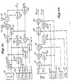
- Figure 2 indicates one structural arrangement which can be utilized in realizing the engine parameter simulator 54 and which further illustrates the previously described electronic simulation of the dependent performance parameter.
- the function generators 92-1, 92-2 and 92-3 can be considered as being arranged for determining the square root of the applied signal s 1 , the square of the applied signal s" and the 3/2 power of the applied signal s l - each of which arrangements can be realized by conventional logic circuits.
- the signals supplied by the function generating units 92-i are coupled to one input terminal of an associated multiplier circuit 94-i, i-1, 2,...,m, with each multiplier circuit 94-i having its second input terminal connected to a storage location 96-i, within a conventional latch or storage register 96.
- the signals which are supplied by the multiplier circuits 94-i can be summed with one another or accumulated to provide the desired estimate of the monitored dependent performance parameter
- the remaining adders 98-4 through 98-(m-1) are connected in a like manner so that the final adder supplies the desired estimate of the dependent performance parameter.
- Figures 3a-3c indicates one arrangement that can be employed in realizing the coefficient estimator 64 of Figure 1 and further illustrates the Kalman recursive digital filtering or signal estimation utilized in this invention.
- Figure 3 illustrates a situation in which a single estimated dependent performance parameter is being monitored wherein the independent performance parameter x 1 is equal to s 1 s 2 and the independent performance parameter X2 is identically equal to s 2 .
- Figure 3 is arranged such that Figure 3a depicts structure that performs the circuit operations mathematically represented by Equation 1-B (determination of an appropriate gain vector G); Figure 3b depicts structure that performs the circuit operations mathematically represented by Equation 1-A (determination of the estimated coefficient vector C); and Figure 3c depicts structure that performs the circuit operations mathematically represented by Equation 1-C (determination of the coefficient error covariance matrix P).
- a conventional latch circuit or storage register 100 stores the values of the P matrix that were obtained during the previous (K-1) operational sequence of the depicted coefficient simulator and were loaded into the latch 100 by an appropriate clock signal at the conclusion of the previous operation sequence.
- the latch 100 holds the matrix P k-1 during the K th coefficient estimation sequence.
- Signals representative of the stored values of P 11 P 12 , P 21 and P 22 are supplied from the latch 100 to one input terminal of conventional multiplier circuits 102-1, 102-2, 102-3, and 102-4, respectively.
- the second input terminal of the multipliers 102-1 and 102-3 are both connected for receiving a signal representative of the current value of the independent performance parameter x 1 (denoted as x 1 (K) in Figure 3a) and the second input terminal of the multipliers 102-2 and 102-4 are both connected for receiving a signal representative of the current value of the independent performance parameter x2(K).
- the latch 90 supplies the signals S1 and s 2 to the two input terminals of a conventional multiplier (function generating unit) 92-1 which thereby supplies the signal x 1 (K) and the signal S2 is supplied as the signal x 2 (K) by the latch 90.
- this vector includes two scalar values in the depicted arrangement.
- the signals supplied by the adders 104 and 106 are respectively supplied multipliers 108 and 110 having the second input terminals thereof connected for respectively receiving the signals X 1 (K) and x 2 (K).
- the signals supplied by the multipliers 108 and 110 are supplied to an adder 112 which also receives a signal representative of the previously described scalar estimate of the modeling error variance R which has previously been stored in a memory register 114.
- the output of the adder 112 is connected to one input terminal of a divider 116 having its second input terminal connected for receiving a signal representative of the scalar 1 which is stored in a read-only memory register 18 or provided by other suitable signal means.
- the signal provided by the divider 116 is coupled to two multiplier circuits 118 and 120 that respectively receive their second input signals from the adders 104 and 106.
- the adders 104 and 106 provide the two terms which result from the matrix multiplication P K-1 X K , it can be recognized that the multipliers 118 and 120 respectively supply signals proportional to the scalar quantities g, and g 2 where g, and g 2 are the two elements of the gain vector G K , i.e., the multipliers 118 and 120 supply the solution to Equation 1-B for the depicted example.
- Figure 3b depicts an arrangement for determining the new coefficient estimates C 1 and C 2 based on the signals g, and g 2 (supplied by the multipliers 118 and 120 of Figure 3a); the coefficients C 1 (K-1) and c 2 (K-1) which are respectively stored in storage registers or latches 122-1 and 122-2 at the completion of the previous (K-1) sequence of the coefficient estimator 64; a signal y K representative of the present actual value of the monitored dependent performance parameter (e.g., a signal supplied by a sensor 58 of Figure 1 and strobed into a latch or memory register 124 at the beginning of the present or K th coefficient estimation sequence); and, the signals x,(K) and x 2 (K) which are supplied as indicated in Figure 3a.
- the coefficients C 1 (K-1) and c 2 (K-1) which are respectively stored in storage registers or latches 122-1 and 122-2 at the completion of the previous (K-1) sequence of the coefficient estimator 64
- a signal y K representative of the
- a multiplier 126 receives signals representative of x 1 (K) and C 1 (K-1) and a multiplier 128 receives signals representative of x 1 (K) and c 2 (K-1).
- the signals supplied by the multipliers 126 and 128 are summed in an adder 130 to thereby provide a signal representative of the term of Equation 1-A.
- This signal is subtracted from a signal representative of the current value of the monitored dependent performance parameter Y(K) within a subtractor 132 and the resultant signal is supplied as an input signal to two multiplier circuits 134 and 136.
- the second input terminals of the multiplier circuits 134 and 136 are respectively connected for receiving the signals representative of the filter gain constants of g, and g 2 which are supplied by the arrangement of Figure 3a.
- an adder circuit 138 receives the signal supplied by the multiplier 136 and a signal representative of the coefficient C 1 (K-1) from the storage register 122-1 to provide the new coefficient estimate C 1 (K).
- an adder circuit 140 receives the signal supplied by the multiplier 134 and a signal representative of the previous coefficient estimate C 2 (k-1) from the storage register 122-2 to supply a signal representative of the new coefficient value C 2 (K).
- the signals C 1 (K) and c 2 (K) are loaded into the storage registers 122-1 and 122-2 for utilization during the next operational sequence of the coefficient estimator or, if coefficients which provide the desired system accuracy have been attained, for use within the engine parameter simulator 54 during operation in the previously described monitor mode.
- Figure 3a depicts an arrangement for determining current values of p 11 p 12 and p 22 i.e., the p K matrix which will be utilized during the nextmost subsequent coefficient estimation sequence (as the matrix P K - 1 ) to determine appropriate filter gains g 1 and g 2 .
- the PX 2 signal supplied by the adder 104 of Figure 3a is combined with a signal representative of the filter gain g 1 (supplied by the multiplier 118 of Figure 3a) in a multiplier circuit 142 and is also combined with a signal representative of the filter gain g 2 (supplied by the multiplier 120 of Figure 3a) in a multiplier 144.
- the PX 2 signal supplied by the adder 106 of Figure 3a is combined with the signal representative of the filter gain g, in multiplier 146 and is also combined with the signal representative of the filter gain g 2 in a multiplier 148.
- the output signals provided by the multipliers 142, 144, 146 and 148 are respectively coupled to the subtractive input terminals of subtractor circuits 149, 150, 152, and 154.
- Signals representative of the elements within the P matrix that were determined during the previous (K-1) operation sequence of the coefficient estimation arrangement of Figure 3 are respectively supplied from the memory locations 100-1, 100-2, 100-3, and 100-4 to the additive input terminals of the subtractors 149, 152, 150 and 154.
- the subtractors 149, 150, 152, and 154 accordingly supply signals representative of the desired matrix elements P 11 (K), P 12 (K), P 21 (K), and P 22 (K).
- the signals are loaded into the memory locations 100-1, 100-2, 100-3 and 100-4 by the previously mentioned clock pulse which is supplied at the conclusion of each operation sequence of the coefficient estimator.
- each operational sequence causes a refinement or improvement in the accuracy of the simulation coefficients and various criteria such as the projected estimation error (y k XKC k _,) of Equation 1-A can be used to determine whether a present value of the coefficients is adequate to effect a desired system monitoring accuracy.
- a second circuit arrangement identical to that indicated by Figure 3, or the very same circuit arrangement can be utilized to obtain the desired trend coefficients by supplying the signals representative of the elapsed monitoring time to the multipliers 102 and the multipliers 126 and 128.
- the coefficient estimator is activated or clocked to perform a single operational sequence each time the engine parameter simulator 54 supplies an estimate of the monitored dependent performance parameter, (i.e., operated once during each system sampling period).
- the arrangement that is not advantageously employed with any particular embodiment of the invention depends primarily on the specific dependent performance parameters being monitored and the fault information that can be obtained by combining such dependent performance parameters.
- those skilled in the art are aware of various fault analyses which can be utilized in an attempt to locate or isolate the engine component or components that cause a particular engine fault.
- diagnostic logic which utilizes conventional combinatorial logic operations (e.g., those effected by conventional AND and OR gates) to indicate problems within various engine stages as the low pressure and high pressure compressors, the low pressure and high pressure turbines, and the combustor assembly on the basis of detected deviations in various engine performance parameters.
- conventional combinatorial logic operations e.g., those effected by conventional AND and OR gates
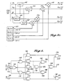
- the circuit arrangement depicted in Figure 4 further exemplifies various logic that can be utilized as the fault logic 62 of Figure 1 and illustrates that such fault logic can be arranged not only to detect a fault within the engine 10, but to also detect various component failures or faults within the monitoring system itself.
- the arrangement depicted in Figure 4 is based on an embodiment of the invention wherein three dependent performance parameters are monitored with the difference unit 56 of this system depicted in Figure 1 accordingly supplying three deviation signals (z" Z2 and Z3 ) which represent the difference between the actual value of each monitored dependent performance parameter and the associated predicted value that is supplied by the engine parameter simulator 54.
- the deviation signals z i , z 2 , and z 3 are respectively supplied to detector circuits 160, 162 and 164 which can be conventional comparator circuits or the like that supply a logical one when the applied deviation signal exceeds a predetermined value. Additionally, the detector circuits 160, 162 and 164 can be arranged for comparing various conventional deviation variables such as percent point of deviation (i.e., 100zkNk) with predetermined threshold values instead of the difference signal (y k -y k ). Further, if desired or necessary, digital filtering of the deviation signals can be performed either within the detector circuits 160, 162 and 164 or prior to supplying the signals to such detector circuits.
- the signals supplied by the detector circuits 160 and 162 are respectively coupled to an input terminal of two AND gates 168 and 170 and are coupled to the two input terminals of a NOR gate 166.
- the AND gates 168 and 170 of Figure 4 are of the type often called inhibit gates in that such gates include an "inverting" input terminal (denoted in Figure 4 by the small circle at such inverting input terminals) that performs the operation of logical negation.
- such gates can be realized by connecting an inverter circuit to one input terminal of a conventional AND gate, and, with respect to a two input AND gate having an inverting input terminal, such a gate supplies a logical one signal only when the signal applied to the inverting input is a logical zero and the signal applied to the other input terminal is a logical one.
- the signal supplied by NOR gate 166 is commonly connected to the inverting input terminals of AND gates 168 and 170 and is also connected to one input terminal of an AND gate 172.
- the second input terminal of the AND gate 172 and an input terminal of two AND gates 174 and 176 are each connected for receiving the signal supplied by the detector circuit 164, with the second input terminals of the AND gates 174 and 176 being respectively connected for receiving the signals supplied by the AND gates 168 and 170.
- a two input AND gate 178 having its input terminals connected for receiving the signals supplied by the AND gates 174 and 176, supplies a signal to a terminal 180 and to the inverting input terminals of two AND gates 182 and 184.
- the second input terminals of the AND gates 182 and 184 are respectively connected for receiving the signals supplied by the AND gates 174 and 176, with the AND gates 182 and 184 respectively supplying a signal to a terminal 186 and a terminal 188.
- the remaining portion of the circuit depicted in Figure 4 includes AND gates 190, 192, 194, 196 and 198 with inverting input terminals of AND gates 190 and 192 receiving a signal from the detector circuit 164; the second input terminals of the AND gates 190 and 192 being respectively connected to the output terminal of the AND gates 168 and 170; the output terminal of the AND gates 190 and 192 being respectively connected to one input terminal of the AND gates 196 and 198 and connected to the two input terminals of the AND gate 194; and, the inverting input terminals of AND gates 196 and 188 both, being both connected to the output terminal of AND gate 194.
- this circuit effectively decodes the eight possible states of the three input signals z 1 , z 2 and z 3 by supplying a signal to one of the circuit output terminals which uniquely identifies the input state.
- each performance parameter deviation signal z effectively assumes a logic level of one when that deviation signal exceeds the threshold value of the associated detector circuit (160, 162 and 164) and a logic level zero when the deviation signal is less than such threshold value, it can be seen that none of the circuit output terminals supplies a logical one when all three deviation signals (z 1 , z 2 and z 3 ) are less than the associated threshold values; the terminal 202 supplies a logical one signal when only z, exceeds its threshold value; the output terminal 204 supplies a logical one signal when only Z2 exceeds its threshold level; and, the output terminal 206 supplies a logical one signal when only z 3 exceeds its threshold.
- the output terminal 200 supplies a logical one when the excessive signals are z, and z 2 ; the terminal 188 supplies a logical one when the signals Z2 and z 3 are excessive; and, the terminal 186 supplies a logical one when the signals z, and z 3 are excessive. Additionally, if all three signals z 1 , z 2 and z 3 exceed their respective thresholds, the terminal 180 supplies a logical one signal.
- the signals provided by the circuit of Figure 4 indicate each possible combination of the fault states of the applied deviation signals, such signals can be utilized to activate the display devices 68 of the annunciator 66 to indicate an engine fault, a fault in one of the sensors 60 that supplies the values of a monitored dependent performance parameter, a fault within the data processor 52 and/or an indication of which engine components cause a detected engine fault.
- the circuit of Figure 4 is connected such that when only one of the deviation signals exceeds its threshold-value, a fault within the portion of the data processor unit 52 that supplies the simulation of the associated dependent performance parameter is indicated; when two of the deviation signals exceed their threshold levels, a fault within a particular one of three system sensors is indicated; and, when all three deviation signals exceed their threshold values, an engine fault is indicated.
- Figure 5 is exemplary of the previously mentioned variety of circuit arrangement which can be utilized in embodying the trend logic 72 of Figure 1.
- an estimate of the engine operating time which remains before engine maintenance would be undertaken is provided by obtaining the positive real solution of the quadratic trend estimate b 2 T 2 +b,T+b o with respect to a limit L (where L reflects the maximum allowable deivation of the monitored dependent performance parameter that is associated with the trending coefficients b o , b, and b 2 ).
- the current value of the limit L (which is stored in a register 210) is subtracted from the current value of the coefficient b o (supplied by a memory register 212) within a subtractor circuit 214, with the difference signal being supplied to a multiplier 216.
- the multiplier 216 also receives an input signal representative of the scalar value 4 (from a latch circuit or read only memory register 218) and a signal representative of the current value of the coefficient b 2 (from a memory register 220) to supply a signal equal to the product of these three input terminals to the subtractive input terminal of a subtractor 222.
- the additive input terminal of the subtractor 222 is supplied a signal representative of the square of the coefficient b 1 by a multiplier 224 having both input terminals thereof connected to a memory register 226 which holds the current value of b,.
- the current value of b is also supplied to one input terminal of a subtractor 228 having its additive input terminal connected to a square root unit 230 which supplies a signal proportional to the square root of the signal supplied by the subtractor 222.
- the signal supplied by the adder 228 is divided within a divider 232 by a signal representative of 2b 2 , which is supplied by a multiplier 234 having one input terminal connected to the memory register 220 and a second input terminal connected to a latch or read only memory register 236 that contains the scalar 2.
- the signal provided by the divider 232 is representative of the positive real solution of the expression which provides an estimate of the time T at which the monitored dependent performance parameter will reach the limit L.
- the system sampling interval Ts (stored in a register 238) is multiplied within a multiplier 242 by the number of times the trend estimation sequence has been performed (stored in a latch 240) and the resulting signal is subtracted from the signal supplied by the divider 232 within a subtractor 244.
- this signal can be displayed on a suitable display device 86 of the annunciator unit 66 ( Figure 1) to provide the aircraft crew and maintenance personnel with an indication of the estimated time remaining until the deviation in the monitored performance parameter reaches the limit L.
- the digital processor 52 of Figure 1 is often preferably realized by a programmable computer.
- computers suitable for use in this invention are not limited to relatively sophisticated computers that are programmed by conventional software techniques, but include computing apparatus commonly identified as microprocessor units which are commercially available in integrated circuit form.
- microprocessor depictted in block diagram form in Figure 6
- ROM read only memory unit
- a central processing unit (CPU) 252 accesses the required system input signals from a conventional input/output unit 254 in accordance with the instructions stored in the ROM 250; performs the necessary arithmetic and logic operations within an arithmetic unit 256, utilizing storage registers within a random access memory unit (RAM) 258 as a "scratch pad memory"; and, stores volatile signal information that must be temporarily retained within the RAM 258.
- RAM random access memory unit
- the estimated coefficients are computed by the microprocessor unit and stored within the RAM 258 for use during operation in the system monitor mode.
- Figure 7 depicts a flow diagram for suitably programming such a computer with a corresponding computer program included herewith as a Technical Appendix.
- each monitoring or calibration sequence begins with a logical determination of whether the monitored engine is operating in a steady state mode of operation.
- this determination which is indicated at the diamond shaped decisional block 260 of Figure 7, is generally effected by testing the value of a signal that is supplied to the digital processor (in this embodiment of the invention a programmable computer of microprocessor circuits) by another component of the monitoring system.
- the steady state sensor 78 of the system arrangement depicted in Figure 1 supplies a signal which is equal to a logical zero when the monitored engine is operating in a steady state condition and is equal to a logical one during transient engine operation.
- the value of this signal is utilized in a branching command to cause the data processor to continue through the operating sequence during steady state engine operation and to return to the "start" condition during periods of transient engine operation.
- the digital processor tests the signals supplied by the system steady state sensor once during each system sampling interval and initiates estimation of the monitored dependent performance parameters (monitor mode) or estimation of the simulation coefficients (calibrate mode) as soon as steady state engine operation is attained.
- the current value of monitored system parameters including both the dependent performance parameters and those engine performance parameters and systems signals that are utilized in forming the independent performance parameters, are determined. For example, with respect to the block diagram of Figure 6, such signals are provided to the digital processor via the input/output unit 254 and stored in memory registers of the RAM 258.
- various ones of the monitored dependent performance parameters are normalized or reduced with respect to pressure and temperature. For example, as previously mentioned, various engine temperatures and rotational speeds of a gas turbine engine being monitored are conventionally normalized relative to sea level pressure (14.7 PSI) and a temperature of 518.7°R.
- the current values of the independent performance parameters are then determined (as indicated at block 266) in accordance with the electronic simulation model that is employed in the particular embodiment of the invention under consideration.
- a set of suitable independent performance parameters for each monitored dependent performance parameter is determined by linear regression analysis of previously available operating data pertaining to the type of engine being monitored and consists of parameters that are the product of various engine performance parameters (and other system signals), rational, real powers of the monitored system signals, and/or scalar values.
- suitable dependent and independent performance parameters for use in monitoring a twin spool, high bypass engine is set forth in the computer program of the Technical Appendix and will be discussed hereinafter.
- the data processor determines whether the system is being operated in the calibrate mode or the monitor mode.
- This determination is a branching operation dependent on the value of a system signal that is at a logical one level when one of the two modes of operation is selected and is at a logical level zero when the system is operated in the other mode.
- a signal is supplied by the mode selector 70 of Figure 1 and, with respect to the previously described embodiments of the invention, the branching operation initiated by this signal effectively realized the switch 74 of Figure 1.
- the digital processor proceeds to the decisional block 270 to determine whether the present operational sequence is the first sequence of the calibrate mode.
- the hereinafter described example computer program utilizes a count index that is incremented during each operational sequence to continuously provide an indication of the number of operational sequences that have been effected (i.e., K in equation 1).
- a conventional digital counter circuit can be included in the system arrangement.
- the coefficient estimator is initialized for determination of the simulation coefficients by establishing the initial values for the P matrix utilized in the previously described Kalman digital filtering (indicated in the block 272 of Figure 7). Following the initialization of the coefficient estimation, the data processor returns to the operational sequence depicted in Figure 7 at a point denoted as "[80]" in Figure 7. On the other hand, if it is determined that it is not the first operational sequence of the calibrate mode (block 270), the initialization of the estimation coefficients is effectively skipped and the data processor sequences to the point [80].
- Each estimated value of a dependent performance parameter is then subtracted from the current measured value of the corresponding parameter to determine the previously described deviation signals (effected at block 276 of Figure 7).
- the deviation signals can be the difference between the current actual value and the current estimate of a dependent performance parameter, or can be other conventional quantities involving this difference.
- each deviation signal is equal to the difference between the actual and estimated values multiplied by 100 and divided by the actual value.
- the data processor supplies these signals to appropriate components of the monitoring system such as the fault logic 62 of Figure 1.
- the data processor stores the deviation signals (e.g., in RAM 258 of Figure 6) for future use.
- the data processor determines the current values of the independent variables of the trending model utilized in the practice of this invention.
- Such operation is simply a transformation of the time variable and is utilized in the computer program of the Technical Appendix.
- the data processor is prepared for determining current estimates of the trend coefficients (b q in Equation 2) that are associated with each of the monitored dependent parameters. More specifically, since the operational sequence of Figure 7 utilizes the same operational steps to determine performance parameter simulation coefficients during operation in the system calibration mode and to determine trend coefficients during operation in the system monitor mode, it is necessary to utilize indicators or "flags" which control the operation of the data processor to reflect certain differences in the determination of simulation coefficients and the determination of trend coefficients.
- the independent variables utilized in determining the performance parameter estimation coefficients are the independent engine performance parameters whereas the independent variables in trend estimation are powers of the variable time (T q in Equation 2).
- the data processor In determining the trend coefficients (operation in the monitor mode) and the simulation coefficients (operation in the calibrate mode), the data processor first determines the current estimated value of each monitored dependent performance parameter (indicated at block 284 of Figure 7) and determines the difference or deviation between the actual value of each monitored performance parameter and the estimated value (indicated at block 286 of Figure 7). In particular, the data processor utilizes the previously mentioned indicators to initiate a series of operations that provide a projected estimate of each dependent performance parameter which is equal to when the system operates in the calibrate mode and provides an estimate of each dependent performance parameter which is equal to when the system operates in the monitor mode.
- the data processor next determines the current values of one or more calibration status indicators V j for each of the monitored dependent performance parameters.
- Each indicator is indicative of the current estimation accuracy relative to an associated performance statistic (e.g., the previously described estimate of the modeling error variance) and, when the system is operating in the calibrate mode, is utilized near the end of the sequence of Figure 7 to cause the data processor to recycle through the sequence to again estimate the performance parameter coefficients until the desired estimation accuracy has been achieved, i.e., performance parameter estimation coefficients are effected which adequately describe the engine being monitored.
- a variance indicator can be utilized as the previously mentioned "measure of confidence" to indicate that the present values of the trend coefficients are reliable indications of engine condition.
- the data processor determines the values of the elements within the vector X'KP K - 1 of the digital filtering or estimation Equation 1-B.
- the necessary values of the P matrix are obtained from the system memory (e.g., RAM 258 of Figure 6). Since, as previously described, the determination of trending coefficients during system operation in the monitor mode and the determination of engine parameter estimation coefficients when the system operates in the calibration mode are mutually exclusive events, it can be recognized that only a single set of n P matrices need be stored in the system memory (e.g., RAM 258 of Figure 6), with the previously mentioned indicators or flags causing the data processor to access the appropriate P matrix.
- the data processor Upon determining the current value of each element of the vector X Tp , the data processor is sequenced to determine the value of the scalar of Equation 1-B (indicated at block 298 of Figure 7) and determines the values of the filter gain vector G of Equation 1-B (indicated at block 294).
- the digital processor utilizes the previously mentioned indicators or flags to access the elements of the X vector and the scalars R (within the system memory or RAM 258) that are appropriate to the coefficient estimation being performed, i.e., operation of the system in the calibrate mode to determine performance parameter simulation coefficients or operation of the system in the monitor mode to determine the trend coefficients.
- the data processor is then sequenced to determine a new P matrix in accordance with Equation 1-C.
- This new P matrix is loaded into the system memory to replace the P matrix utilized in the present operational sequence and therefor becomes the P matrix for the next operational sequence of the data processor.
- the data processor determines the new or current estimated values of the coefficients for each of the monitored dependent performance parameters (indicated at block 298 of Figure 7) in accordance with Equation 1-A, and replaces the previously stored coefficient values with the newly computed values.
- the portion of the operational sequence of Figure 7 which includes block 284 through block 298 effectively realizes coefficient estimator 64 of Figure 1.
- the portion of the operational sequence which includes blocks 290 through 294 realizes the arrangement depicted in Figure 3a; the portion of the sequence indicated at block 296 realizes the arrangement depicted in Figure 3c; and, the portion of the sequence indicated at block 298 effectively realizes the arrangement depicted in Figure 3b.
- the data processor then again determines the operational mode of the monitoring system (indicated at decisional block 300). This determination is made in the manner described relative to decisional block 268 and institutes a branching operation which causes the digital processor to return to the beginning of the sequence of Figure 7 (via sequence point [100] if the system is being operated in the monitor mode and causes the digital processor to initiate the portion of the operational sequence denoted at block 302 of Figure 7 when the system is being operated in the calibrate mode.
- each status indicator V j (determined during the portion of the operational sequence denoted as block 288) is compared to a predetermined limit value to determine whether the present performance parameter coefficients properly characterize the engine to be monitored, i.e., determine whether the calibration mode is complete.
- the indicated branching operation is effected by subtracting the predetermined limits from the variance indicators and testing the differences. If the differences are all not less than zero, the calibration mode is not complete and the data processor proceeds to update or modify the parameters of the status indicator determination made at block 288 of Figure 7 for the next operational sequence of the data processor.
- the digital processor initiates the portion of the operational sequence denoted at block 306 to determine whether it is necessary to initialize the data processor for the estimation of trend coefficients during the next system monitoring interval. More specifically, and as described relative to filter Equations 1-A through 1-C, if the system has not previously operated in the monitoring mode with respect to the gas turbine engine presently being monitored, the initial values of the elements within the P matrix must be established for use in estimating a trend coefficient during the first operational sequence of the data processor.
- This operation is effected by the portion of the sequence of Figure 7 denoted as block 308, with the data processor loading the initial values of the P matrix into the previously mentioned portion of the system storage allotted to the calibration P matrix and advancing to point 100 to await the initiation of the next operational sequence. If it is determined during the portion of the sequence denoted by the decisional block 306 that the system has previously been operated in the monitoring mode to establish estimated values of the trend coefficients, the data processor sequences directly to point 100 to await the start of the next system monitoring sequence.
- each statement within the computer program of the Technical Appendix includes a line number (a four digit number in the left-most columns of field); can include an "instruction address” a one to three digit number in the next field that is utilized, for example, to represent appropriate storage addresses in branching and loop operations; and, includes an arithmetic or logic statement.
- various "comments” which are of no computational or logical consequence are included to provide programming information, such comments being identified by a "C" which is located between the field containing the line numbers and the field containing the instruction addresses.
- the computer program begins at line 1 with a "dimensioning statement" that effectively instructs the computer as to the amount of storage required for various variables that are utilized during each operational sequence.
- the variable Z represents the monitored dependent performance parameters with five parameters being monitored and the variable XT represents independent performance parameters with 33 various combinations of easily monitored system signals being utilized in the embodiment of the invention that employs the disclosed computer program.
- Lines 2-9 establish initial values of the indicated variables for use during the first operational sequence of the system. For example, at line 3, the 115 coefficient values that are utilized as simulation coefficients and trend coefficients are initially established equal to zero. As previously described, because of the accuracy of the electronic simulation utilized in this invention, initial coefficient values of zero are generally satisfactory and suitable values of the simulation coefficients which characterize the engine being monitored relative to other engines of the same type are derived during operation in the system calibrate mode.
- the operational sequence begins at line 10 (instruction address 1) with a "continue" instruction which corresponds to the "start" block of Figure 7.
- the initial logical operation is a determination of whether the monitored engine is in steady operation, with the disclosed computer program utilizing the variable IM to denote the system signal which indicates steady state or transient engine operation (line 11 of the program).
- the current values of the monitored system signals are determined (e.g., read into storage), various signals are normalized to form the desired set of dependent performance parameters (Z), the current value of the independent performance parameters (XT) are determined and computational indices J1 and J2 are established which control operation of the computer during subsequent portions of the operational sequence.
- PPA power level angle
- the five monitored dependent performance parameters are respectively EPR; N1/ ⁇ , where 6 is a normalization factor equivalent to the square root of TT2/518.7°R; N2/8; EGT/62; and W/(PT2/14.78).
- the first 20 independent performance parameters (XT(1) through XT(20)) are employed in the estimation of each of the first four dependent performance parameters (Z(1) through Z(4)), and the independent performance parameters XT(14) through XT(33) are employed in the estimation of the fifth dependent performance parameter Z(5).
- each set of independent performance parameters that is associated with a particular dependent performance parameter is selected by statistical analysis of engine system operating data (linear regression) that relates to the type of engine being monitored so that the independent performance parameters generically characterize the type of engine to be monitored with the simulation coefficients characterizing the particular engine being monitored relative to others of the same type.
- linear regression engine system operating data
- the estimation of certain ones of the dependent performance parameters utilized in the disclosed computer program such as N1 and N2 does not necessarily require use of all 20 independent performance parameters (X T (1) through X T (20)) to attain the desired estimation accuracy (e.g., one percent).
- the twenty independent performance parameters used for the estimation of the dependent performance parameter Z(5) includes independent performance parameters Z(14) through Z(20) which are also included in the set of twenty independent performance parameters used in estimating the dependent performance parameters Z(1 ) through Z(4).
- the computer program of the Technical Appendix includes a computational index J1 which is initially set equal to zero (line 13) to cause the computer to access the first 20 independent performance parameters (XT(1) through XT(20)) during the determination of the first four dependent performance parameters (Z1) through Z(4).
- the index J1 is set equal to 13 at appropriate points of the operational sequence to cause the computer to access independent performance parameters XT(14) through XT(33) for the estimation of the independent performance parameter Z(5).
- the disclosed computer program utilizes a computational index J2.
- This index is set equal to 20 during portions of the computational sequence in which engine modeling is being effected and is set equal to 3 during portions of the computational sequence in which engine trend information is being determined with the numerals 20 and 3 denoting the number of independent variables utilized in these two operations.
- the IF statement at line 55 effects the branching command indicated at block 268 of Figure 7, with the variable IC being supplied to the computer being equal to 1 when the system is operated in the calibrate mode, e.g., the signal supplied by the system mode selector 76 in the system arrangement of Figure 1.
- the instruction at line 72 sets an address index J4 equal to zero, such address index causing the computer to access the proper coefficients during the digital filtering operation in which new simulation coefficients are estimated.
- the IF statement at line 73 corresponds to the decisional block 270 of Figure 7 and causes the computer to establish initial values of each P matrix utilized in the previously described Kalman digital filtering during the first operational sequence or iteration that is performed when the system is placed in the calibrate mode.
- the IF statement of line 73 causes the computer to test the value of a computation index CK, which is set equal to zero at line 5 of the first computational sequence performed under the control of the disclosed computer program and incremented by one with each subsequent iteration.
- the disclosed computer program utilizes scalar operations and does not require matrix operations
- the indexing arrangement utilized in the disclosed computer program is such that P(1) through P(100) correspond to five consecutive sets of 20 covariance values that, in turn, correspond to the first column of the five P matrices described relative to Equations 1-A through 1-C; P(101) through P(200) includes five consecutive sets of 20 covariance values that correspond to the second column of the five P matrices, etc.
- the first column of the matrix of Equations 1-A through 1-C that is associated with determining the appropriate coefficients (C) for simulation of Z(1) correspond to the elements P(1) through P(20) of the disclosed computer program; the second column of this P matrix corresponds to elements P(101) through P(120),..., and the twentieth column of this P matrix corresponds to the elements P(1901) through P(1920).
- the disclosed computer program first sets each element equal to zero (DO loop at lines 74 and 75) and then (at lines 76 through 79) establishes a dummy variable K1 and a nested DO loop to establish each element that corresponds to a diagonal in one of the P matrices of Equations 1A through 1C equal to an initial value P o , which is read into computer memory during the first operational sequence of the system (line 4 in the disclosed computer program).
- each initial P matrix is a positive definite matrix, which, as previously described is necessary to ensure that each successive iteration of the herein described calibration sequence will result in an improvement in the accuracy of the simulation coefficients, i.e., convergence of the coefficient estimation sequence.
- the computer begins the estimation of the required simulation coefficients at address 80 (line 80 of the disclosed computer program) where the previously described computational index J1 is set equal to zero.
- the computer is sequenced through a series of nested DO loops (lines 81 through 134) which cause the computer to determine a set of simulation coefficients for each of the monitored dependent performance parameters that is based on the difference between the current actual value of a monitored dependent performance parameter and the estimated value of the same dependent performance parameter that is obtained during the current iteration.
- the DO loop initializes the computational variables XTC to a value of zero.
- the DO loop index I is tested to determine whether the computer is estimating the value of one of the first four dependent performance parameters (Z(1) through Z(4)) or is estimating the value of the fifth dependent performance parameter (Z(5)). If one of the first four dependent performance parameters is being estimated, the computational index J1 is permitted to remain equal to zero in order to cause the computer to access the first wp independent performance parameters (XT(1) through XT(20)) during the ensuing estimation calculations. On the other hand, if Z(5) is being estimated, J1 is set equal to 13 so that the computer will utilize the dependent performance parameters XT(14) through XT(33).
- the computer While the computational index J1 established to select the proper independent performance parameters and the computational variable XTC initialized at zero, the computer is sequenced through a DO loop set forth at lines 84-86 to determine the current estimated value of one of the dependent performance parameters. For example, during the first pass through the nested DO loop arrangement of lines 81 through 134, the DO loop index I is equal to one and the computer determines the estimated value of Z(1), which is temporarily stored as the computational variable XTC.
- the computer determines the difference between the current value of the monitored dependent performance parameter Z(1) and the estimated value of the parameter XTC, such operation providing the difference signal generally denoted as y-y in the description of the embodiment of the invention depicted in Figures 1-5.
- One quantity that can be utilized as the status indicator described relative to block 288 of Figure 7 is then calculated at lines 88 and 89; the indicated status indicator V(I) being numerically equal to a recursive estimate of the variance of the above-mentioned difference between the actual and estimated values of the dependent performance parameter, where C1 and C2 are scalar quantities that are initialized at lines 8 and 9 of the computer program and updated in value during each iteration of the calibration sequence (lines 140 and 141).
- each pass through the DO loop of lines 90 through 95 loads 20 scalar values which, in equivalent matrix notation, constitute one row of the matrix P K - 1 discussed relative to Equations 1A-1C with the value of K1 being established to denote the array index within working storage and the value of K2 being established to access the proper scalar value within the stored array PC.
- the first dependent performance parameter Z(1) is estimated at line 86 of the program, I is equal to one and the DO loop index L is set equal to one.
- the DO loop index M is incremented between one and 20 (the value of J2 during calibration operation) to cause the index K1 to be incremented in steps of 20 and sequence from one to 38a, while simultaneously causing the index K2 to be incremented in steps of 100 and sequence between one and 1901.
- the computer loads 20 elements of the stored PC array (corresponding to the first row of the P K - 1 matrix of Equations 1-A through 1-C) as the first 20 elements of P array.
- the disclosed computer program sequences the computer through a series of scalar operations that correspond to determining the 20 element vector X Tp , which is indicated at block 290 of Figure 7 and is denoted as X r K P K - 1 in Equations 1-B and 1-C. More specifically, each time the computer sequences through the DO loop of lines 96-100, one element of the PX array is calculated with the index M identifying the element being calculated and the DO loop index L being incremented from one through 20 to access the proper independent performance parameters and the proper element of the previously described P array.
- a temporary computational variable YT is initialized to zero at line 101 of the disclosed computer program and a DO loop set forth at lines 102 through 104 accumulates the 20 products of an appropriate element of PX array (element of the X Tp matrix operation) multiplied by an appropriate one of the 20 independent performance parameters (element of the X T array).
- the computer is then sequenced to determine an array of 20 Kalman gain constants which correspond to G K in Equation 1-B and the operation denoted at block 294 of the operational sequence depicted in Figure 7. These gain constants are determined by the DO loop set forth at lines 106 and 107 of the computer program.
- the computer is sequenced to determine a second type of status indicator TR(1), which corresponds to the previously mentioned matrix trace operation of the current coefficient error covariance matrix (P K - 1 in Equations 1-B and 1-C) and to update the elements of the matrix P K of Equation 1-C, which is utilized if the computer is again sequenced through the calibration sequence (i.e., if the current calibration sequence does not provide simulation coefficients of a suitable accuracy).
- the status indicator TR(1) where I denotes the index of the associated dependent performance parameter Z(1), and hence a particular set of simulation coefficients, is initially set equal to zero at line 108.
- each element of the term GKXKPK -1 of Equation 1-C is calculated (line 114).
- the m m elements of this matrix are then temporarily stored in the idle sector of the PC array to conserve computer storage.
- the computer program sequences through the outer DO loop (lines 109 through 117) wherein the DO loop index L is utilized to cause the computer to update "L" row elements of the P array with each pass through the DO loop.
- the computational indices K1 and K2, established at lines 112 and 113 cause the computer to calculate new elements for the P array that correspond to a diagonal element of the P K matrix of Equation 1-C along with each element lying to the left of the diagonal in that particular row of the P K matrix.
- the computer calculates a single element P(1) which corresponds to the upper left-hand (diagonal) element of the matrix P K defined by Equation 1-C and sets the status indicator TR(1) equal to this scalar value.
- the computer calculates two scalar values corresponding to the first and second (diagonal) element of the second row of P K and adds the scalar value that corresponds to this diagonal element to TR(1).
- TR(I) is equal to the summation of all 20 diagonal elements as the DO loop sequence is completed.
- ths status indicator is normalized relative to the initial covariance error coefficient, P o at line 118 of the computer program.
- each element of the P array that corresponds to a right-hand off-diagonal element of the P K matrix is set equal to the value of one of the left-hand off-diagonal elements such that the P array corresponds to a symmetrical matrix when the DO loops of equations 119 through 125 are completed.
- the element P(399) which corresponds to the element that lies in the 19th row and 20th column of the P K matrix, is set equal to P(380), which corresponds to the element of P K matrix that lies in the 20th row and the 19th column.
- the computer is then sequenced to calculate the new values of the simulation coefficients associated with the dependent performance parameter Z(I) (indicated at block 298 of Figure 7 and by Equation 1).
- the DO loop set forth at lines 126 through 128 of the disclosed computer program causes the computer to update those 20 simulation coefficients that are associated with the estimation of the dependent performance parameter Z(I) during operation of the system in the monitor mode.
- the instructions at lines 129 through 133 of the disclosed computer program cause the computer to execute a DO loop that replaces the values stored in the PC array with the scalar values contained in the matrix P K calculated during this operational sequence.
- the new PC elements thus correspond to the elements of the P K - 1 matrix to be utilized during the next operational sequence.
- each of the status indicators is compared to a limit, denoted as CSTOP, which was loaded into computer memory at lines 7 of the computer program. If the value of any of the status indicators exceeds CSTOP, the computer is sequenced through lines 139 through 142 which updates a count index CK, updates the scalar values C1 and C2 that are utilized in determining the status indicator V(I) and sequences the computer to instruction address 1 (line 10) to thereby cause the computer to re- execute the above-described - calibration sequence and thereby form improved sets of coefficients.
- CSTOP a limit
- the simulation coefficients determined during that particular execution of the above-described calibration sequence are sufficient to ensure the desired accuracy of this system during operation in the monitor mode.
- the computer is sequenced to line 143 (instruction address 10) by the instruction at line 138, which corresponds to block 306 of the operational sequence depicted in Figure 7.
- the IF statement at line 143 determines whether or not it is necessary to initialize 45 scalar values of the stored PC array that correspond to the five 3x3 matrices of covariance error coefficients utilized in the digital filtering portion of the trending sequence (operation of the system in the monitor mode). More specifically, when the system is first installed to monitor a particular engine and the calibration sequence is completed, it is then necessary to establish initial P matrices for the first operational sequence of the system monitor mode. This initialization sequence is initiated by detecting the value of a count index KT at line 143 (instruction address 10 of the disclosed computer program).
- KT Since the count index KT is set equal to zero at line 6 of the program during the first operational sequence after installation of the system for monitoring a particular engine and is incremented by one at the completion of each monitoring sequence (line 151 of the program), KT will be equal to zero only when the system has not previously operated in the monitor mode and at all times thereafter will be indicative of the period of time that the engine has been monitored.
- the instruction at line 143 causes the mode indicator IC to be set equal to zero (line 144) to indicate that the calibration sequence is complete and that the ensuing computer operation should be performed in the monitor mode. Further, in the manner described relative to initialization of the PC array during operation of the system in the calibrate mode, the DO loop of lines 145 through 150 causes the first 45 elements of the stored PC array to correspond to five 3x3 matrices having diagonal elements equal to P o and off-diagonal elements equal to zero.
- the computer increments the count index KT (line 151) and sequences the computer to instruction address 1 (line 10) to thereby cause the computer to cycle through one operating sequence of the monitor mode.
- the computer begins an operational sequence of the monitoring mode by accepting new values of the monitored system parameters and calculating the corresponding current values of the dependent performance parameters (Z(1) through Z(5)) and the independent performance parameters (XT(1) through XT(33)) in accordance with the program instructions of lines 10-54.
- the Z array contains scalar values corresponding to y-y of the embodiments of the invention described relative to Figures 1-5 for each of the five dependent performance parameters, such values being made available to the system fault logic (e.g., fault logic 62 of the system arrangement of Figure 1) for the previously described signal processing that produces the system fault indications.
- system fault logic e.g., fault logic 62 of the system arrangement of Figure 1
- the computer is then sequenced to effect the previously described parameter trending estimation in which the trending coefficients of a quadratic estimate of the time dependent behavior of each monitored dependent performance parameter are estimated.
- the system determines the coefficients bq for an estimate mathematically represented by
- the disclosed computer program causes the computer to calculate the current value of the independent trend variable (unity, KT and KT 2 ) and load the appropriate values of the independent trend variables into computer memory. Since the current values of the independent performance parameters which are stored in the XT array are no longer required, the independent trend variables are stored as elements 1-3 and elements 14-16 of the XT array to further reduce computer storage requirements.
- the computer is sequenced to set the previously described computation indices J4 and J2 respectively equal to 100 and 3 to cause the computer to properly dimension the instruction statements utilized during the trend coefficient estimation sequence and to access the proper stored parameters during this estimation sequence.
- the computer is then sequenced to instruction address 80 (line 80 of the program) to form the previously described digital filtering sequence and estimate the current values of the trend coefficients.
- These 45 trend coefficients are then stored as elements 101 through 145 of the coefficient array C and are supplied to the system trend logic (e.g., logic 72 in the system of Figure 1) for activating the system trend displays (e.g., annunciator unit 66 of Figure 1).
- the indicator IC is equal to zero and the count index KT is greater than one.
- the computer is sequenced from the instruction at line 135 to instruction address 100 (line 151 of the program), which increases the count index KT and sequences the computer to instruction address 1 (at line 10) for the start of the nextmost monitoring sequence.
- the following computer program is one example of a program that can be utilized in an embodiment of the invention which employs a programmable digital computer as the system digital processing unit.
Landscapes
- Physics & Mathematics (AREA)
- General Physics & Mathematics (AREA)
- Engineering & Computer Science (AREA)
- Automation & Control Theory (AREA)
- Testing And Monitoring For Control Systems (AREA)
Abstract
Description
- This invention relates to a system for analyzing the performance of a gas turbine engine. More particularly, this invention relates to a system for monitoring a gas turbine engine wherein various engine performance parameters are sensed and compared with predicted values of the same parameters to supply deviation or error signals indicative of the condition of the engine.
- In the gas turbine engine arts, the need for apparatus and methods for monitoring the performance of a gas turbine engine to provide diagnostic information such as the detection of an engine fault and provide prognostic information such as the time the engine can be operated until maintenance procedures are required has long been recognized. The need for such apparatus and techniques is especially apparent with respect to gas turbine engines, which power aircraft, since the failure of these engines often causes delayed departures and maintenance problems which are not only costly to the aircraft operator, but, in the case of commercial transport aircraft, cause inconvenience and potential economic loss of passengers and the shippers of freight. Further, the present practice of overhauling aircraft gas turbine engines after an empirical period of operation is not cost effective in that, although such practice tends to minimize the probability of inservice engine failure, many engines are prematurely removed from service for maintenance or overhaul. In addition, it has been recognized that a gas turbine monitoring system which provides an immediate indication of engine malfunction or impending failure will allow an aircraft crew to take immediate action which can minimize damage to the engine and further enhance aircraft safety margins.
- Accordingly, a variety of systems have been proposed to monitor and analyze the operation of a gas turbine engine in a manner which detects engine malfunction or failure and/or provides diagnostic or prognostic information that is of value in engine maintenance and overhaul operations. Basically, these prior art monitoring systems can be classified as either ground based systems which utilize engine data gathered during previous flights of the aircraft or as airborne systems which either continuously or periodically sense various engine performance parameters.
- Generally, the ground based systems include equipment on the aircraft to periodically record the values of various engine performance parameters during periods of aircraft operation in which the monitored engine is operated under predetermined conditions and include a ground based monitoring station which generally utilizes a large scale digital computer. In the operation of such a system, recorded engine performance data is either transmitted to the ground based monitoring station or, more typically, stored on magnetic tape or other media within the aircraft for delivery to the ground station at a later convenient time. Once the engine data is received at the ground station, it is generally "conditioned" by filtering techniques to remove a substantial portion of the noise content and to normalize the data so that it is amenable to processing within the particular computer and analysis routine that is employed. After such conditioning and normalization, the data is stored within a data bank for later computer processing. Generally, this processing is performed on a periodic basis to determine the temporal or trend characteristics of the monitored engine parameters, which trend information is useful in supplementing periodical overhaul policies to prevent premature removal of an engine. Additionally, when an engine fails in service, the previously recorded engine performance data can be processed within the computer to aid in determining the cause of engine failure and hence ensure that adequate overhaul procedures are followed before the engine is returned to service.
- Although such ground based engine monitoring systems have both diagnostic and prognostic capabilities, several disadvantages and drawbacks are presented. First, and foremost, the analysis of gas turbine engine performance is not effected as the engine operates (i.e., in "real- time" or "on-line") but, because of delays encountered in recording the engine data, transmitting it to the ground station and analyzing the data within the computer, the diagnostic and prognostic capabilities of the system are limited. For example, such "after-the-fact" analysis may not be readily available when an engine must be removed and quickly restored to service. Further, such after-the-fact analysis does not provide the flight crew with current engine performance data and in-flight procedures which could prevent serious engine damage cannot be initiated. In addition, although such a ground based station can serve a number of aircraft, the costs associated with operating such a system are relatively high both in terms of the required investment in equipment and the labor costs involved in operating and maintaining such a system.
- Previously proposed gas turbine engine monitoring systems that are operable in an airborne application are known from US-A-3,750,465.
- In this specification a method is described for monitoring at least one performance parameter of a gas turbine installation, the method comprising the steps of:
- - supplying at least a signal representative of the current value of each monitored performance parameter;
- - supplying a plurality of signals representative of an associated plurality of operating parameters of the engine installation being monitored, said plurality of signals being selected so that a linear combination of said signals provides a current estimate of each monitored performance parameter;
- - compiling a signal being a linear combination of said plurality of signals, thus being a current estimate of each performance parameter;
- - calculating the difference of the signals representing the current estimates of each monitored performance parameter and the signals representing the current value of each corresponding performance parameter to difference signals;
- - processing said difference signals to obtain signals indicating a fault in said engine installation.
- A major drawback of this known method lies in the fact that although gas turbine engines are manufactured and refurbished in accordance with strict dimensional tolerances, the actual performance parameters of engines within a particular type deviate from theoretical or nominal values by an amount that is significant with respect to the accuracy requirements of a monitoring system which will detect minute changes in engine performance parameters to thereby indicate engine deterioration before serious engine failure occurs. Thus, most prior art gas turbine engine monitoring systems which rely on a theoretical engine model are inherently limited in monitoring accuracy. Systems such as those disclosed by the known specification at least partially overcome this limitation by utilizing previously recorded data that is obtained from the engine being monitored as the engine monitoring reference or base line. However, attaining a high degree of accuracy in such a system not only requires that the differential equations which model or simulate the thermodynamic characteristics of the type of engine being monitored precisely describe such thermodynamic characteristics, but also requires that each engine of a particular type exhibits exactly the same characteristics. Since structural variations do occur because of manufacturing and installation tolerances and since gradual deterioration in performance occurs throughout an engine's operating life, the constant coefficient modeling approach utilized in the system disclosed by the known specification cannot provide the degree of accuracy that is necessary or desired in exacting engine monitoring applications.
- Another disadvantage of known monitoring systems lies in the problem of sensor inaccuracies or signal noise which is commonly encountered with commercially available pressure and temperature sensors. In this respect, in a system such as that disclosed in the known specification, wherein system accuracy depends on the validity of recorded base line data, precisely defining the base line information would generally require several measurements at each operating point to obtain a statistically valid mean value. This procedure would generally require a fairly sophisticated digital computer having a nonvolatile memory that is capable of storing the large amount of collected data throughout the operation life of the monitored engine. Since such computers are not only economically unattractive for airborne engine monitoring applications, but also increase the weight and structural complexity of the monitoring system, a highly accurate system of the type disclosed in the known specification may not be practical or desirable.
- Therefore the object of the invention is to provide a monitoring system for gas turbine engines of wihch system the accuracy does not depend on theoretical models nor on manufacturing tolerances, the accuracy nevertheless being sufficient for detecting minute changes in engine performance characteristics.
- Another object of the invention is to provide a monitoring system for gas turbine engines which is immune to sensor inaccuracies and to signal noise.
- Both objects of the present invention are achieved by providing both a method according to
claim 1 and a system according toclaim 2. - US-A-3,731,070 describes a monitoring system for a gas turbine engine which system comprises means to compute the rate of change of several different thermodynamically independent variables. However, this system still suffers from the drawbacks of insufficient accuracy due to sensor inaccuracies and signal noise, and of dependencies on theoretical models and their limitations.
- US-A-3,750,465 describes a steady state detector, which serves the purpose of blocking out spurious signals.
- The same specification also describes a fault indicator. However, as indicated before, the system according to US-A-3,750,465 describes a system with the drawbacks as mentioned above.
- In each embodiment of the invention, system sensors detect the current value of engine operating data, including various engine performance parameters, air data signals and/or engine control signals, and supply signals representative of this data to a digital processor unit that utilizes these signals (and certain functions thereof in predicting current values of one or more engine parameters that are indicative of deterioration in engine performance. For purposes of descriptive clarity, the predicted engine performance parameters are referred to hereinafter as dependent performance parameters of variables and the engine operating data (or signals representative thereof) that are utilized in the prediction of these dependent performance parameters are hereinafter referred to as independent performance parameters or variables; such terminology being with reference to the parametric interrelationship between these parameters within the methe- matical description of the electronic simulation or modeling that is utilized in the practice of this invention.
- More specifically, in accordance with this invention, the electronic simulation or modeling that is achieved by the digital processor can be represented methematically by the matrix equation:
- Y=CX+E, where Y is a column vector comprising the predicted dependent engine performance parameters, X is a column vector comprising the independent performance parameters, C is a matrix of scalar coefficients, and E is a column vector comprising scalar elements which represent modeling inaccuracies. For example, in an embodiment of the invention wherein n dependent engine performance variables are estimated and m independent performance variables are utilized in the electronic simulation of each dependent performance variable, Y and E are column vectors each having n elements, X is a column vector having m elements and the coefficient matrix C includes m elements in each row and n elements in each column. Thus, it can be recognized that, in accordance with the electronic simulation or modeling that is utilized in this invention, each dependent engine parameter yk, k=1, 2,...,n is mathematically equivalent to

- In accordance with this invention, such electronic simulation or modeling does not rely only on those sets of dependent and independent engine parameters which, through appropriate coefficients, are known in the art to parametrically describe the steady state thermodynamic gas generator characteristics of the type of engine being monitored. Rather, in accordance with this invention, the independent engine parameters x,, i=1, 2,...,m are preferably selected from easily monitored engine data such as various engine performance parameters, air data signals and engine command signals through statistical analysis of data which reflects performance of an engine of the type to be monitored. In particular, in accordance with this invention, a set of independent engine parameters (Xi) for estimating the values of a set of desired dependent engine parameters is determined from engine performance data of the particular type of engine to be monitored (e.g., a Pratt-Whitney JT8 or JT9 type engine, of even more generally, any high bypass, twin spool gas turbine engine), by linear regression analysis of such engine performance data. It has been found that, when the independent engine parameters are selected in this manner, such parameters are generic to, and uniquely characterize, the type of engine being monitored whereas the coefficients (c) distinguish a particular engine being monitored from others of the same type to thereby account for normal engine manufacturing and installation tolerances. Further, since the data utilized to determine the independent engine parameters can reflect engine performance over any desired range of steady state engine operating conditions (e.g., flight at various Mach numbers, altitudes, throttle positions and ambient air temperature), the selected set of independent engine parameters provides valid and accurate prediction of the dependent engine parameters over a corresponding range of operating conditions. Accordingly in the practice of this invention, system accuracy is maintained over a wide range of engine operating conditions which can include the entire range of steady state operating conditions that are encountered in the normal operation of the aircraft which utilizes the monitored engine.
- To automatically adapt a monitoring system of this invention to the particular engine being monitored the system is operable in an in-flight calibration mode wherein digital signal filtering is employed to determine values of the coefficients c that are appropriate to the particular engine being monitored. These coefficients are stored within memory registers and utilized until the engine being monitored is replaced or the monitoring system or engine is otherwise modified in a manner which requires new coefficient values in order to restore and maintain the desired system accuracy. More specifically, in each disclosed embodiment of the invention, recursive digital filtering of the type commonly identified as Kalman filtering is implemented within the digital processor to provide the desired coefficients. In this digital filtering arrangement, the digital processor estimates the current value of each monitored dependent engine parameter based on current values of the coefficients c and the current values of the independent engine parameters x; determines the error between the estimated and actual values of the monitored dependent engine parameters y; and, updates the values of each stored coefficient c such that the estimation error decreases. By sequentially operating in this manner, the data processor continues to refine the values of the above-described coefficients until a desired prediction accuracy is achieved. Further, since the calibration mode can be effected in flight with the monitored engine being operated under normal flight conditions, the final coefficient values are not related to either a hypothetical nominal engine and/or to an engine operating state that does not represent actual flight conditions.
- In accordance with the invention, signals representative of the estimated value of each dependent engine performance parameter are supplied to a difference unit which can be realized within the digital processor unit or by other conventional electronic circuitry. Within the difference unit, the signals are compared with signals representative of the actual current value of each of the dependent engine parameters (provided by a set of sensors mounted to or within the engine being monitored), to supply deviation signals that represent the difference between the estimated and actual values of each dependent performance parameter. These deviation signals are coupled to monitoring logic which combines the signals to detect a fault within the digital processor, the system sensors, or the gas turbine engine.
- Additionally, to detect deterioration in engine performance that is attributable to normal engine wear or precipitated by abnormal operating conditions, the deviation signals are utilized within the digital processor to supply signals which estimate the temporal characteristics or trends associated with any or all of the monitored dependent engine performance parameters. This trend information is of considerable prognostic value to the flight crew and to maintenance personnel in that such information allows estimation of the time at which the monitored engine will require overhaul, maintenance activity, or procedural changes relative to the manner in which the engine is operated. Thus, such information can complement or even supplant the conventional procedure of removing an engine for maintenance or overhaul after an empirically determined period of operation or after the occurrence of a malfunction. Further, the trend signals provided in accordance with this invention are indicative of the rate at which deterioration in engine performance is occurring. Thus, a prediction of imminent engine malfunction resulting from causes other than normal performance deterioration can be provided.
- In accordance with this invention, the trend signals are supplied by augmenting the electronic simulation or modeling arrangement of the data processor to include time dependent terms that are capable of characterizing the time varying drift in the values of critical engine performance parameters, i.e., the monitored dependent engine parameters, which changes in engine performance that are attributable to sources such as normal engine wear. In particular, in an embodiment of the invention which includes performance trending capability, operation of the electronic simulation or modeling of each dependent engine parameter can be represented by the mathematical expression

- In the disclosed embodiments of the invention, recursive digital filtering is employed to supply signals representative of the trend coefficients bo, b"...,bq that are associated with each monitored dependent engine performance parameter every time the digital processor unit monitors the value of that particular engine parameter. In particular, Kalman filtering or estimation is utilized wherein the data processor uses the previously mentioned deviation signal (difference between the actual and estimated value of the dependent engine parameter) to determine the current values of the trend coefficients. Thus, in accordance with this invention, current values of the trend coefficients reflect changes that occur in the monitored dependent engine parameters over the entire period in which the system is interconnected with the monitored engine installation. Accordingly, the trend coefficients are capable of characterizing relatively subtle (i.e., very slow) changes in engine performance.
- The signals which represent each of the trend coefficients are supplied to trend logic which utilizes combinatorial logic to provide an indication of prognostic information such as the estimated number of hours the engine can be operated prior to overhaul, go/no-go dispatchability of the aircraft and in-flight warning of a predicted imminent engine malfunction.
- Like most systems which incorporate sequential digital operations and combinatorial logic, the monitoring system of this invention can be structured in a variety of manners. For example, in embodiments wherein relatively few engine performance parameters need be monitored and the monitored dependent parameters can be characterized by relatively few independent engine parameters, an embodiment of this invention can utilize hard-wired arrangements of commercially available digital integrated circuits or discrete circuit components. On the other hand, in embodiments in which several dependent engine variables are to be monitored and/or several independent engine parameters are required to achieve the desired system accuracy, a programmable computer is advantageously employed to implement at least the digital filtering and performance parameter modeling. As shall become apparent upon attaining a more complete understanding of the invention, computers suitable for use in such embodiments not only include conventional airborne computers of the type that are programmed by conventional software techniques, but also include relatively small and simple computing devices such as those conventional integrated circuits commonly called microprocessors. As is known in the art, such microprocessor arrangement can be programmed by software techniques, hardwire connections, stored information such as read-only memory units (i.e., "firm-wire"), and various combinations thereof.
-
- Fig. 1 is a block diagram of a gas turbine engine performance monitoring system constructed in accordance with this invention;
- Fig. 2 is a block diagram that is useful in understanding the electronic simulation or modeling used in the practice of this invention and further illustrates one manner of structurally embodying the electronic modeling portion of the digital processor depicted in Fig. 1;
- Fig. 3 is a block diagram which is useful in understanding the digital signal filtering utilized in the practice of this invention and illustrates one manner of embodying the coefficient estimator depicted in Fig. 1;
- Fig. 4 is a circuit diagram of a logic arrangement which can be utilized in the practice of this invention to realize the fault logic depicted in Fig. 1;
- Fig. 5 is a circuit diagram of an arrangement useful in understanding the trend logic illustrated in the block diagram of Fig. 1, which arrangement represents one type of trend logic which can be utilized in the practice of this invention;
- Fig. 6 is a block diagram of sequential digital apparatus, such as a programmable digital computer or microprocessor circuit which can be utilized in various embodiments of the invention to realize the coefficient estimator and/or of the electronic modeling depicted in Fig. 1; and,
- Fig. 7 is a flow chart which illustrates typical programming of the digital computer or microprocessor of Fig. 6 for use in realizing electronic modeling and coefficient estimation in an embodiment of this invention.
- Fig. 1 depicts a monitoring system of this invention arranged for monitoring the performance of a gas turbine engine of the high bypass twin spool variety (generally denoted by the numeral 10). As is known in the art, such a gas turbine engine is mounted within a nacelle or
outer housing 12 which defines anair inlet duct 14 at the forward end of the engine 10. Theair inlet duct 14 supplies airflow to allow pressure, low speed compressor orfan stage 18 which is journalled within thenacelle 12. A portion of the air supplied by thefan stage 18 is supplied to a high pressure,high speed compressor 22 and the remaining portion is exhausted rearwardly through an annular duct 24 which is formed between theouter housing 12 and an inner housing 26 that encloses thecompressor 22 and other elements of the engine core. - The high pressure air exits the
compressor 22 to a generallyannular combustor assembly 27. Fuel, injected into thecombustor assembly 27 by a series of nozzles (not shown in Fig. 1) is mixed with the compressed air and ignited within thecombustor assembly 27. The hot combustion gases exiting thecombustor assembly 27 drive a highpressure turbine stage 28 which, in turn, drives the highpressure compressor stage 22 through ashaft 30. A lowpressure turbine stage 32, which is connected to the lowpressure compressor stage 18 by a shaft 34 that passes coaxially through theshaft 30, is driven by the combustion products exiting the highpressure turbine stage 28. As the high temperature, high velocity conbustion products exit theturbine 32, the gases flow rearwardly through anexhaust nozzle 38 for discharge into the atmosphere as a thrust producing fluid stream. In the simplified diagrammatic engine representation of Fig. 1, theexhaust nozzle 38 is an annular duct that is formed between the inner housing 26 and arearwardly projecting tailcone 40. - It will be recognized by those skilled in the art that twin spool, high bypass gas turbine engines can include structure not diagrammatically set forth in the engine 10 of Fig. 1. For example, such engines can be of the mixed flow variety wherein at least a portion of the fan bypass stream is not exited to the atmosphere through the duct 24, but flows rearwardly around the inner housing 26 and is mixed with the hot combustion products which exit the
turbine state 32 to provide increased thrust and lower jet noise. Further, theair inlet 14 andexhaust nozzle 38 can be of controllable or variable geometry to respectively permit control over the airflow entering the engine and the expansion characteristics of the hot combustion products. As shall be recognized upon understanding the present invention, the hereinafter described monitoring system of this invention is not restricted to the particular type of engine 10 depicted in Fig. 1, but is suitable for use with virtually any type of gas turbine engine presently known or contemplated, including those used in applications other than propelling an aircraft. Further, although the following description of the invention is made with reference to a fixed configuration engine (i.e., an engine not having variable geometry inlet or exhaust nozzle structure), it will be recognized that the present invention can be practiced with engines having variable geometry structure by controlling the monitoring system of this invention so that engine monitoring is effected during periods in which the engine geometry is of a certain fixed configuration. Alternatively, in some situations, monitoring of variable geometry engine installations over a range of engine geometry will be possible by including means for sensing the present geometry of the engine and adaptively modifying the hereinafter described structure to compensate or account for engine performance parameter changes that occur due to the variable geometry structure. - Regardless of the type of engine being monitored, the performance monitoring system of this invention includes a number of sensors interconnected with the engine 10, sensors interconnected with control apparatus which determines the operating state of the engine 10, and conventional air data apparatus or appropriate sensors which supply signals representative of parameters such as aircraft speed and altitude. More specifically, in the arrangement of the invention depicted in Fig. 1, a first set of sensors 42-1, 42-2,...,42-n, which are enclosed within
broken line 44, supply signals representative of pressure or temperature at various locations or stations within the engine 10; a power level angle (PLA)sensor 46 supplies an electrical signal representative of the angular position of athrottle lever 48 which controls a fuel controller 50 to establish the engine power setting; and theair data system 51 of the aircraft utilizing the invention supplies signals representative of air data information which is utilized in the operation of the invention. As shall be described in more detail hereinafter, the number of signals utilized in the practice of this invention and the identity of each sensed parameter is determined both by the type of engine being monitored and by the desired system accuracy. - As is indicated in Fig. 1, the signals supplied by the set of
sensors 44, thePLA sensor 46 and theair data system 51 are coupled to adigital processor unit 52 and in particular to a portion of thedata processor 52 which is identified in Fig. 1 as anengine parameter simulator 54. As will be recognized by those skilled in the art, in a situation in which the above-described sensors and air data system supply analog signals, conventional analog-to-digital converters (not shown in Fig. 1) can be employed to provide appropriate digital signals to thedigital processor 52. Further, in situations in which the sensors and/or air data system supply digital signals in a format different than that utilized within thedigital processor 52, conventional digital-to-digital convertors can be employed. - The signals supplied by the set of
sensors 44, thePLA sensor 46, and the air data system 51 (denoted as signals s1,s2,...,sP in Fig. 1) are utilized by theengine parameter simulator 54 to determine a set of signals y1, y2,..., yn which represent the predicted or estimated values of a number of engine performance parameters. More specifically, and in terms of a mathematical description of the system operation, theengine parameter simulator 54 is arranged to supply a set of signals Y=CX where Y is a column vector which includes n estimated engine performance parameters, X is a column vector having m elements that are functions of the supplied signals s1, i=1, 2,...,p (i.e., elements such as sj, Sq multiplied by s" and Su t/v where j, q, r, t, u, and v are members of the set of positive and negative integers encompassing the range from one to m); and, C is a coefficient matrix of scalar elements having n rows and m columns. Thus, in scalar notation, each of the estimated performance parameters 9k, k=1, 2,...,n, is equal to
- It can be noted that, in the above mathematical expressions, the estimated or predicted engine performance parameters (Yk) are dependent variables and the functions of the sensed engine operating signals (x,) are independent variables. In accordance with this mathematical distinction and for the sake of descriptive clarity, those engine performance parameters that are estimated or predicted by the
electronic parameter simulator 54 will be referred to hereinafter as dependent performance parameters. In a similar manner, those engine installation parameters and air data parameters utilized within theengine parameter simulator 54 to estimate the dependent performance parameters (e.g., the signals denoted as s1, s2,...,sP in Fig. 1) and the functions thereof which are denoted as x1, x2,...,xm in the above mathematical expressions will be referred to as independent performance parameters. It should become apparent from the following paragraphs that a particular engine parameter which is treated as a dependent performance parameter can also be utilized as an independent per-' formance parameter in predicting the value of another dependent performance parameter. - In the practice of this invention, the independent performance parameters are not selected such that the above stated mathematical expressions reflect the gas generator characteristics of the particular engine being monitored. Rather, the independent performance parameters are selected from easily measured engine performance parameters, engine control functions, and air data information such that each selected set of independent performance parameters is statistically correlated with an associated dependent engine parameter. Essentially this distinction between the present invention and prior art gas turbine engine performance monitoring systems provides sets of independent performance parameters which are generic to and uniquely characterize the performance characteristics of the particular type of engine to be monitored whereas the associated coefficient values distinguish the particular engine being monitored from other engine units of the same type. Thus, through the automatic determination of the electronic simulation coefficients that is effected when the system of Fig. 1 is operated in the hereinafter described calibration mode, prior art problems and limitations associated with performance deviations between engines of the same manufacture and type that result because of engine manufacturing and installation tolerances are overcome. Further, as shall hereinafter become apparent, the electronic modeling or performance parameter simulation of this invention permits the present invention to be embodied such that a single embodiment of the invention is easily adaptable to the monitoring of any particular type of gas turbine engine.
- Various techniques are known to those skilled in the art for obtaining a set of independent performance parameters which satisfy the above mentioned requirements in particular, when dependent performance parameters such as the rotational speed of the low
pressure compressor state 18 of Fig. 1 (generally denoted in the art as N1), the fuel flow rate W, the engine pressure ratio (EPR), or the engine exhaust gas temperature (EGY) are to be determined, suitable independent performance parameters can be ascertained by applying known linear regression analysis techniques to engine operating data which includes information on these parameters and various other engine system variables which can be useful as independent performance parameters. Such system variables include the previously mentioned air data information such as aircraft altitude and speed, PLA and numerous measurable engine performance parameters. The data necessary for determining a suitable set of independent performance parameters can be gathered, for example, by operating a gas turbine engine of the type to be monitored and recording the pertinent engine operating information with apparatus such as that used in prior art ground based engine monitoring systems. Alternatively, such performance data is often made available by an engine manufacturer in the form of punched data cards or magnetic tape. - In any case, once the desired engine operating data is available, linear regression analysis of data can be performed, for example, by known digital computing techniques wherein a computer is programmed to either automatically or, under the control of an operator, determine a set of independent variables and a set of corresponding coefficients which statistically describe a desired dependent variable in accordance with the data supplied to the computer and within a desired accuracy (e.g., within a specified least mean square error). Although the coefficients obtained by this analysis can be utilized as a "starting point" within an embodiment of this invention for automatically determining those coefficients which characterize the particular engine being monitored, it has been found that such a procedure is usually unnecessary and, as shall be described hereinafter, embodiments of this invention generally determine proper modeling coefficients even when arbitrary initial values (e.g., zero) are utilized.
- At this point, it should be recognized that the above-described electronic simulation of this invention and the associated method of determining suitable independent performance parameters permits the invention to provide precise monitoring accuracy over virtually any range of engine operation. In particular, the engine operation data that is utilized in selecting the independent performance parameters can include data collected with the engine operating under various steady state conditions including various aircraft speeds, various power level settings (PLA), and various external temperatures and pressures. Since a set of independent performance parameters selected in this manner reflects the operation of the engine in each of these operating states, the selected independent performance parameters will be valid in determining a predicted value of the associated dependent performance parameter over a corresponding range of engine operation. Accordingly, the present invention overcomes various other prior art difficulties that were previously set forth herein and a desired performance monitoring accuracy can generally be obtained over the entire operating regime of a monitored engine. For purposes of comparison with prior art airborne performance monitoring systems, it can be noted that the electronic simulation accuracy achieved with this invention generally is within the percentage point of the actual value of the predicted dependent performance parameter.
- Having now a basic understanding of the operation of this invention to effect electronic simulation or modeling of a dependent performance parameter and with continued reference to Fig. 1, the estimated dependent performance parameters (y1, y2,...,yn) are supplied to one set of input terminals of a
difference unit 56. A second set of input terminals of thedifference unit 56 receives signals representative of the actual value of the dependent performance parameters (denoted as Y1, Y2,...,yn in Fig. 1) which are supplied by a set of conventional sensors that includes sensors 60-1, 60-2,...,60-n. As is known in the art, it is often advantageous to normalize engine performance parameters in a standard temperature and pressure (e.g., 14.7 pounds/square inch and 518.7°R). In embodiments of the invention where parameter normalization is desired or necessary, the system of Fig. 1 can include suitable signal conditioning apparatus for normalizing appropriate ones of the performance parameters y;. - The
difference unit 56 is a conventional circuit arrangement that determines the difference in value between each monitored dependent performance parameter yj, j=1, n and the corresponding estimated dependent performance parameter y,, j=1,...,n to thereby supply a set of deviation signals,
system fault logic 62 and to a portion of thedigital processor 52 that is identified in Fig. 1 as asimulator coefficient estimator 64. Alternatively, in hereinafter described embodiments of the invention wherein theengine parameter simulator 54 and/or thesimulator coefficient estimators 64 are realized by a programmable digital computer or microprocessor circuit, such computer or microprocessor can be programmed to provide the deviation signals. -
Fault logic 62 includes an arrangement of conventiona) logic gates or other logic circuit arrangements for logically combining the deviation signals in a manner which supplies one or more signals indicative of a fault within thesystem sensors 60, thedata processor 52, and/or the gas turbine engine 10. For example, in one arrangement that is depicted in Figure 4, the system utilizes threesensors 60 and thefault logic 62 is an arrangement of logic gates which supplies signals indicative of a fault within any one of the three sensors, a fault in the electronic simulation of each of the three estimated dependent performance parameters (fault within digital processor 52) or a fault within the engine 10. - The signals supplied by
fault logic 62 are coupled to anannunciator unit 66 to energizedisplay units 68 that visually indicate the detected fault condition to the flight crew or other concerned personnel. Thedisplay units 68 can be a variety of conventional devices ranging from conventional indicator lamps and aural warning devices to more complex apparatus such as hard copy printout devices. - In accordance with this invention,
coefficient estimator 64 is arranged to effect digital signal filtering which determines the modeling coefficients (c) during operation of the invention in the calibrate mode and to effect similar digital filtering during engine performance monitoring (system operation in "monitor" mode) which provides signals indicative of temporal characteristics of the deviations in the monitored dependent performance parameters. Such temporal characteristics or trend information indicate gradual engine deterioration which is attributable to normal wear and also can provide an indication or warning of an imminent engine fault. As is indicated in Figure 1, thecoefficient estimator 64 is controlled by asystem mode selector 70 such that the coefficients determined by thecoefficient estimator 64 are directed to theengine parameter simulator 54 when the system is operated in the calibrate mode and are directed to atrend logic unit 72 when the system is operated in the monitor mode. More specifically, in the arrangement of Figure 1, switching apparatus which is schematically represented by a conventional single pose,single throw switch 74 is activated in conjunction with a conventional selector switch 76 of thesystem mode selector 70 such that the coefficient signals supplied by thecoefficient estimator 64 are routed in the previously described manner. - The selector switch 76 of
mode selector 70 is also utilized in conjunction with asteady state sensor 78 which detects whether or not the monitored engine is operating in a steady state condition (e.g., whether or not the engine is being controlled to transist between operating states at a relatively rapid rate) to inhibit operation of the monitoring system during transient operating conditions. Although, in some situations it may be possible to utilize a monitoring system of this invention under nonsteady state operating conditions, the values of the monitored dependent performance parameters are not necessarily correlated with the independent performance parameters in the same manner as they are during steady state operation. Accordingly, extremely accurate performance monitoring may not be effected during periods of nonsteady state operation and it is often advantageous to inhibit system operation during the short periods of time in which the engine is not operating in a steady state condition. - A suitable
steady state sensor 78 can be configured in a variety of manners and generally compares an engine command signal such as the commanded rotational speed of the low pressure compressor orfan stage 18 in the engine 10 with the actual value of the parameter (i.e., N1). For example, in thesteady state detector 78 of Figure 1, one input terminal of acomparator 80 is connected to a terminal 82 which receives a signal proportional to the commanded fan speed (or other suitable engine command) and the second input terminal of thecomparator 80 is connected to the sensor 42-1 for receiving a signal representative of the actual value of N1. Thus, thecomparator 80 supplies an output signal (i.e., a logical one) only when the actual value of N1 corresponds to the commanded value. This output signal is connected to an inverting input terminal of a two-input ANDgate 84. The second input terminal of the ANDgate 84 is connected to the selector switch 76 of themode selector 70 which is interconnected such that an electrical potential equivalent to a logical one is supplied to the ANDgate 84 whenever the system is operating in either the calibrate or monitor mode. Thus, ANDgate 84 will supply an inhibit signal which is a logical one during nonsteady state conditions and will supply a logical zero during operation of the engine in a steady state condition. This signal is supplied to theengine parameter simulator 54 to effectively disable electronic parameter simulation during nonsteady state conditions. - Like the electronic simulation utilized in this invention, the general arrangement of the
coefficient estimator 64 can best be understood by first considering the underlying mathematical expressions which describe the digital filtering that is effected within this portion of the invention. More specifically, the digital filtering that is effected within thecoefficient estimator 64 is known to those skilled in the art generally as recursive digital filtering, and is particularly known as Kalman signal filtering or estimation. - In matrix notation, the Kalman filtering utilized for each of the dependent parameters is given by the expressions:




- Regardless of whether the
coefficient estimator 54 is utilized to supply trend signals (operation in the monitor mode) or in the determination of coefficient values for theengine parameter simulator 54 which distinguish the particular engine being monitored from other engines of the same type (operation in the calibration mode), thecoefficient estimator 54 proceeds through a series of operations in which it combines various system signals and the above defined variable P and G to determine a set of coefficient values C which will be utilized in the next operational sequence of thecoefficient estimator 54. More specifically, during operation in the calibrate mode, thecoefficient estimator 54 sequentially determines an estimated coefficient vector (CK) for each of the monitored dependent performance parameters 9m, k=1, 2,...,n. As is indicated by Equation 1-A, each estimated coefficient vector is based on the previous value of the coefficient vector (tK-1), i.e., the coefficient values determined during the nextmost antecedent coefficient estimation sequence, a gain vector (GK) and the projected value of the previously described associated deviation signal
coefficient estimator 64 during the previous or nextmost antecedent coefficient estimation sequence and a scalar value of R which is selected in view of modeling accuracy and repeatability of thesensors 58 in Figure 1. Appropriate error variance terms R can be determined by conventional a priori regression analysis (e.g., the variance of the regression residuals) and by augmenting such variance terms with empirically or statistically obtained terms relating to thesensors 60. Additionally, to provide a proper matrix PK for use during the nextmost operating sequence (as the matrix PK-1)' thecoefficient estimator 64 combines the gain vector (G) with the present values of the independent performance parameters (X) and the error covariance matrix that was determined during the nextmost antecedent coefficient estimation sequence (PK-1). - From Equations 1A through 1C and from the above description, it can be recognized that each embodiment of the
data processor 52 necessarily includes storage registers for maintaining signals representative of the coefficient vector C, and a coefficient error matrix P. Additionally, it can be recognized that initial values of these quantities should be contained within the appropriate storage registers to enable thecoefficient estimator 64 to begin operation, i.e., values for use during the first operating sequence of the system calibration mode. In this respect, and as previously mentioned, the coefficients which result during the statistical analysis utilized in selecting a set of suitable independent variables Xi, 1=1, 2,...,m can be utilized as the initial coefficients of the matrix C. However, because of the accuracy and reliability of the electronic simulation and digital filtering utilized in this invention, it has been found that arbitrary initial coefficient values (e.g., zero) can be utilized without affecting either the overall system accuracy or substantially increasing the number of sequential estimation operations required to obtain coefficients which distinguish the monitored engine from all others of the same type. Further, it is noteworthy that, through initial evaluation and analysis of this invention, it has been found that a set of selected independent performance parameters which are satisfactory for use with one particular engine are often satisfactory for use with another type of engine. For example, with respect to gas turbine engines of the twin spool high bypass variety, the same set of independent performance parameters is generally capable of characterizing either the JT8 or JT9 engines, manufactured by Pratt-Whitney, or a CF-6 engine, manufactured by General Electric Company. Because of this and the above- noted fact that the system calibration mode provides suitable coefficients even when arbitrary coefficient values are initially assumed, it can be recognized that it is possible to embody the invention such that the monitoring system is not only self adaptive to a particular engine within a particular type of engine (e.g., the previously mentioned JT8 engine), but is self-adaptive to any particular engine within a rather broad engine class (e.g., high bypass, twin spool gas turbine engines). - The initial values of the elements of the P matrix are generally best determined experimentally during the design of each particular embodiment of this invention. In this respect, it can be shown that, in order to ensure convergence in the coefficient estimation with repetitive operation of the
coefficient estimator 64, the initial P matrix must be a positive definite matrix. In particular, it has been found that satisfactory results are obtained by utilizing a positive definite diagonal matrix for P wherein each off-diagonal element is equal to 0 and each diagonal element is equal to the product CpTR[P*], where Cp is an experimentally determined constant selected to provide a dynamic filtering range sufficient to achieve the desired calibration accuracy over the engine operating range of interest, P* is the coefficient dispersion matrix (as determined during the linear regression analysis utilized in selecting the independent performance parameters) and TR[ . ] indicates the matrix trace operation. - In a performance monitoring system of this invention which is embodied to provide the previously mentioned trend information, the electronic parameter simulation that is effected within the
data processor unit 52 is augmented to include a polynomial of time dependent terms, and signals representative of the coefficients of such time dependent terms are coupled to thetrend logic 72. More specifically, in such an embodiment of the invention, theengine parameter simulator 54 electronically simulates the current value of each dependent engine parameter 1'k, k=1, 2,...,n, in accordance with the mathematical expression:

- With respect to choosing a suitable order r for the time dependent polynomial, it has been found that utilizing first order or linear trending estimation (i.e., a time dependent term b1T+b0) does not generally provide satisfactory results, especially with respect to rapidly changing deviations in the monitored dependent performance parameter. On the other hand, it has been found that a quadratic trending polynomial

- In considering the previous discussion of the Kalman filtering that is effected in accordance with this invention, it can be recognized that the trend coefficients bq, q=0, 1,...,r can be determined by procedure and structure substantially identical to that used in determining the simulation coefficients during the operation of the system in the calibrate mode. In particular, it can . be recognized that if a vector T which includes the elements Tq, q=0, 1,...,r is substituted for the independent performance parameters (X) in the previously described operation of the
coefficient estimator 64, and the deviations zi are substituted for the dependent parameters y,, and estimated trend coefficient vector B having elements bq, q=0, 1,...,r will be supplied with each sequential operation of thecoefficient estimator 64. Further, if such a coefficient estimator is utilized and activated to provide a trend coefficient estimate, each time theengine parameter simulator 54 provides an estimate of the associated dependent performance parameter k, k=1, 2,...,n, a set of trend coefficients bq will be supplied for each dependent performance parameter which accurately describes the time varying deviation of that particular dependent performance parameter. It should be noted since the estimation of trending coefficients and the estimation of simulation coefficients are mutually exclusive events in that the former is necessary only when the system is operating in the monitor mode and the latter is necessary only when the system is operating in the calibrate mode, it is possible to simplify the structural arrangement of thecoefficient estimator 64 through a logic design to effectively share a single logic circuit. In a similar manner, in the embodiment of the invention described relative to Figure 7, a digital computer or microprocessor utilizes a single set of computational and logic instructions to effectively realize the operation of thecoefficient estimator 64 in determining both the performance parameter simulation coefficients and the trend coefficients while simultaneously realizing theengine parameter simulator 54. Regardless of the type of embodiment employed, and as previously mentioned, signals representative of the trend coefficients bq, q=0, 1,...,r are supplied to thetrend logic 72 during each monitoring operation of the system depicted in Figure 1. -
Trend logic 72 can include a variety of arrangements for providing prognostic information that is based on the supplied trend coefficients and which provides an appropriate indication to the aircraft crew (e.g., through a conventionalalphanumeric display unit 86 in Figure 1). With respect to various arrangements for utilizing the trend coefficients of a quadratic trend estimation, it can be seen that each coefficient bo effectively represents a bias term which reflects the total deterioration that has occurred in an associated dependent performance parameter monitored by the system throughout the entire period of engine monitoring (accumulated steady state operating time); each coefficient b, effectively represents the present rate of change relative to the deterioration in each associated dependent performance parameter; and, each coefficient b2 effectively represents an "acceleration" or the present time rate of change in the deterioration rate of each associated dependent performance parameter. Thus, in some situations, it may be advantageous to implementtrend logic 72 such that the coefficients b2 and b1 are compared to preascertained limits to assure that no rapid changes in the deterioration of a dependent performance parameter are taking place and such that the coefficient bo is compared with another preascertained limit, which is representative of the deterioration in the associated dependent performance parameter that should be tolerated prior to engine recalibration, overhaul or maintenance. Such an implementation can provide a go/no-go dispatchability status of the aircraft. Various other methods and apparatus for utilizing the trend coefficients supplied in accordance with this invention will be apparent to those skilled in the art, for example, the coefficients b1 and b.2 can be combined to detect relatively rapid changes in coefficient value to thereby detect a sudden increase in the deterioration rate of one or more of the monitored performance parameters. Such an implementation would be indicative of an imminent engine fault. Further, an arrangement for determining the estimated engine operating time which remains before engine overhaul or maintenance should be undertaken will be described relative to the trend logic arrangement that is depicted in Figure 5. - As is known, the accuracy of an arrangement for recursive signal estimation or digital filtering such as the Kalman filtering utilized to estimate the trend coefficients increases with the amount of signal data that is processed. In this respect, it can be said that the signal estimate asymptotically converges to the true signal value as the number of times the previously described filtering or estimation sequence has been performed increases. Since, as previously described, the trend coefficients are estimated each time the
digital processor 52 supplies an estimated value of the associated dependent performance parameter, it can thus be recognized that the system of this invention effectively requires a "gestation period" before highly accurate trend information is provided. In this respect, it is also known that the number of operational sequences which are required for a specified coefficient estimation accuracy depends on factors such as the amount of signal noise present (signal-to-noise ratio) and the system signal sampling rate. In this respect, present indications are that sampling rates on the order of 10-40 samples per hour are generally satisfactory and enable the trending estimator to detect deterioration rates in the monitored dependent performance parameters on the order of 0.001 percent to 0.04 percent per sampling interval with an estimation accuracy of at least 1 percent. In such an embodiment, 60 hours or less of steady state engine operation is required for the estimated trend coefficients to reach the desired accuracy. Further, the trend coefficients can be utilized before 60 hours of engine operation have been accumulated if compromises can be made in the estimation accuracy. For example, in one evaluation of the invention wherein a one percent estimation accuracy is achieved within 60 hours of engine operation, the trending estimation was accurate within a standard deviation of 4 percent after 40 hours of engine operation. - Generally, the fact that precise trending information is not available until the engine has been monitored for a specific time (i.e., until a sufficient number of trending estimates have been performed) is not a substantial limitation. In this respect, the need for the prognostic information is generally not as great during such an initial period of engine operation. Because of this characteristic, however, it may be advantageous to provide apparatus for manually or automatically disabling the trend indication (such as the
display device 86 in Figure 1) until this initial period has elapsed. Alternatively, it will be recognized by those skilled in the art that, during each of the sequential operations thecoefficient estimators 64, the coefficient error covariance matrix P is indicative of the relative accuracy of the supplied trend coefficients. Accordingly, signals representative of this matrix can be combined by an appropriate logic arrangement to activate an indicator when the desired estimation accuracy is attained. Further, if desired, signals representative of the matrix P can be utilized in a suitable logic arrangement to provide a continuous indication of the error in the trend coefficients and thereby provide a constant measure of confidence in the supplied trend information. - Figure 2 indicates one structural arrangement which can be utilized in realizing the
engine parameter simulator 54 and which further illustrates the previously described electronic simulation of the dependent performance parameter. In the arrangement of Figure 2, the signals supplied, for example, by the set ofsensors 44, andPLA sensor 46 and theair data system 51 which are utilized to form the independent performance parameters (x,, i=1, 2,...,m) are loaded into a digital storage register or latch 90 in time coincidence with a timing signal that is supplied by a system clock (not shown in Figure 2) which supplies one pulse at the beginning of ecah system sampling period. The signals supplied to thelatch 90 are coupled to function generating units 92-i, i=1, 2,...,m which are arranged to supply current values of the desired independent performance parameters xm where, as previously described, each independent performance parameter is identically equal to one of the signals s,, is equal to the product of two (or more) signals Sk and sj, or is a single signal sµ raised to a rational power. For example, in the arrangement indicated in Figure 2, function generating unit 92-4 can be a conventional multiplier circuit to thereby supply a signal x4=s1s2. Further, for the sake of illustration, the function generators 92-1, 92-2 and 92-3 can be considered as being arranged for determining the square root of the applied signal s1, the square of the applied signal s" and the 3/2 power of the applied signal sl- each of which arrangements can be realized by conventional logic circuits. - To determine the product of the signals x" i=1, 2,...,m and the associated simulation coefficients c;m, i=1, 2,...,m, the signals supplied by the function generating units 92-i are coupled to one input terminal of an associated multiplier circuit 94-i, i-1, 2,...,m, with each multiplier circuit 94-i having its second input terminal connected to a storage location 96-i, within a conventional latch or
storage register 96. Since the previously described simulation coefficients are loaded into the storage locations 96-i from thecoefficient estimator 64 during operation of the system in the calibrate mode, the signals which are supplied by the multiplier circuits 94-i can be summed with one another or accumulated to provide the desired estimate of the monitored dependent performance parameter

difference unit 56 of Figure 1. - The arrangement collectively depicted by Figures 3a-3c indicates one arrangement that can be employed in realizing the
coefficient estimator 64 of Figure 1 and further illustrates the Kalman recursive digital filtering or signal estimation utilized in this invention. For simplicity, Figure 3 illustrates a situation in which a single estimated dependent performance parameter
- Referring now to Figure 3a and assuming that the depicted arrangement is performing the "Kth" operational sequence of the previously described system calibration mode, a conventional latch circuit or
storage register 100 stores the values of the P matrix that were obtained during the previous (K-1) operational sequence of the depicted coefficient simulator and were loaded into thelatch 100 by an appropriate clock signal at the conclusion of the previous operation sequence. Thus, in terms of Equation 1-B, thelatch 100 holds the matrix Pk-1 during the Kth coefficient estimation sequence. Signals representative of the stored values of P11 P12, P21 and P22 (where the two numerals of each subscript respectively denote the row and column location of the scalar values which comprise the matrix P) are supplied from thelatch 100 to one input terminal of conventional multiplier circuits 102-1, 102-2, 102-3, and 102-4, respectively. The second input terminal of the multipliers 102-1 and 102-3 are both connected for receiving a signal representative of the current value of the independent performance parameter x1 (denoted as x1(K) in Figure 3a) and the second input terminal of the multipliers 102-2 and 102-4 are both connected for receiving a signal representative of the current value of the independent performance parameter x2(K). - In the arrangement of Figure 3, the signals x1(K) and x2(K) are supplied by structure corresponding to that described relative to the arrangement of Figure 2, and in accordance with the previously mentioned example of x1=s1s2 and x2=s2. In particular, in the arrangement of Figure 3a, the
latch 90 supplies the signals S1 and s2 to the two input terminals of a conventional multiplier (function generating unit) 92-1 which thereby supplies the signal x1(K) and the signal S2 is supplied as the signal x2(K) by thelatch 90. - To provide signals representative of the vector

adder circuit 104 and the signals supplied by the multipliers 102-3 and 102-4 are summed within anadder circuit 106. As is denoted by the terms PX1 and PX2 in Figure 3a, this vector includes two scalar values in the depicted arrangement. - The signals supplied by the
adders multipliers 
multipliers adder 112 which also receives a signal representative of the previously described scalar estimate of the modeling error variance R which has previously been stored in amemory register 114. To provide a signal representative of the reciprocal of the signal supplied by theadder 112, the output of theadder 112 is connected to one input terminal of adivider 116 having its second input terminal connected for receiving a signal representative of the scalar 1 which is stored in a read-only memory register 18 or provided by other suitable signal means. The signal provided by thedivider 116 is coupled to twomultiplier circuits 118 and 120 that respectively receive their second input signals from theadders adders multipliers 118 and 120 respectively supply signals proportional to the scalar quantities g, and g2 where g, and g2 are the two elements of the gain vector GK, i.e., themultipliers 118 and 120 supply the solution to Equation 1-B for the depicted example. - Figure 3b depicts an arrangement for determining the new coefficient estimates C1 and C2 based on the signals g, and g2 (supplied by the
multipliers 118 and 120 of Figure 3a); the coefficients C1(K-1) and c2(K-1) which are respectively stored in storage registers or latches 122-1 and 122-2 at the completion of the previous (K-1) sequence of thecoefficient estimator 64; a signal yK representative of the present actual value of the monitored dependent performance parameter (e.g., a signal supplied by asensor 58 of Figure 1 and strobed into a latch ormemory register 124 at the beginning of the present or Kth coefficient estimation sequence); and, the signals x,(K) and x2(K) which are supplied as indicated in Figure 3a. In particular, in the arrangement of Figure 3b, amultiplier 126 receives signals representative of x1(K) and C1(K-1) and a multiplier 128 receives signals representative of x1(K) and c2(K-1). The signals supplied by themultipliers 126 and 128 are summed in anadder 130 to thereby provide a signal representative of the termof Equation 1-A. This signal is subtracted from a signal representative of the current value of the monitored dependent performance parameter Y(K) within a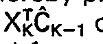
subtractor 132 and the resultant signal is supplied as an input signal to twomultiplier circuits 134 and 136. The second input terminals of themultiplier circuits 134 and 136 are respectively connected for receiving the signals representative of the filter gain constants of g, and g2 which are supplied by the arrangement of Figure 3a. Additionally, anadder circuit 138 receives the signal supplied by the multiplier 136 and a signal representative of the coefficient C1 (K-1) from the storage register 122-1 to provide the new coefficient estimate C1(K). In a similar manner, anadder circuit 140 receives the signal supplied by themultiplier 134 and a signal representative of the previous coefficient estimate C2(k-1) from the storage register 122-2 to supply a signal representative of the new coefficient value C2(K). As the Kth operating sequence of the coefficient estimator ends, the signals C1(K) and c2(K) are loaded into the storage registers 122-1 and 122-2 for utilization during the next operational sequence of the coefficient estimator or, if coefficients which provide the desired system accuracy have been attained, for use within theengine parameter simulator 54 during operation in the previously described monitor mode. - Figure 3a depicts an arrangement for determining current values of p11 p12 and p22 i.e., the pK matrix which will be utilized during the nextmost subsequent coefficient estimation sequence (as the matrix PK-1) to determine appropriate filter gains g1 and g2. In the circuit depicted in Figure 3c, the PX2 signal supplied by the
adder 104 of Figure 3a is combined with a signal representative of the filter gain g1 (supplied by themultiplier 118 of Figure 3a) in amultiplier circuit 142 and is also combined with a signal representative of the filter gain g2 (supplied by the multiplier 120 of Figure 3a) in amultiplier 144. In a like manner, the PX2 signal supplied by theadder 106 of Figure 3a is combined with the signal representative of the filter gain g, inmultiplier 146 and is also combined with the signal representative of the filter gain g2 in a multiplier 148. The output signals provided by themultipliers subtractor circuits 149, 150, 152, and 154. Signals representative of the elements within the P matrix that were determined during the previous (K-1) operation sequence of the coefficient estimation arrangement of Figure 3 (i.e., p11(k-1), p12(k-1), p21(K-1) and P22(k-1) are respectively supplied from the memory locations 100-1, 100-2, 100-3, and 100-4 to the additive input terminals of thesubtractors 149, 152, 150 and 154. Viewing this arrangement, it can be recognized that thesubtractors 149, 150, 152, and 154 accordingly supply signals representative of the desired matrix elements P11(K), P12(K), P21(K), and P22(K). To make these signals available for use within the circuit arrangement of Figure 3a during the next operational sequence, the signals are loaded into the memory locations 100-1, 100-2, 100-3 and 100-4 by the previously mentioned clock pulse which is supplied at the conclusion of each operation sequence of the coefficient estimator. - In view of the above-described single operation sequence of the coefficient estimation arrangement of Figure 3, it can be recognized that coefficient estimation described relative to the operation of the system of Figure 1 in the calibration mode can be effected by repetitive operation (clocking) of the arrangement depicted in Figure 3. As described relative to Equations 1-A through 1-C, each operational sequence causes a refinement or improvement in the accuracy of the simulation coefficients and various criteria such as the projected estimation error (ykXKCk_,) of Equation 1-A can be used to determine whether a present value of the coefficients is adequate to effect a desired system monitoring accuracy. Further, from the previous description of the estimation of trend coefficients, it can be recognized that a second circuit arrangement identical to that indicated by Figure 3, or the very same circuit arrangement, can be utilized to obtain the desired trend coefficients by supplying the signals representative of the elapsed monitoring time to the multipliers 102 and the
multipliers 126 and 128. As previously discussed, during trending operation, the coefficient estimator is activated or clocked to perform a single operational sequence each time theengine parameter simulator 54 supplies an estimate of the monitored dependent performance parameter, (i.e., operated once during each system sampling period). - As described relative to the system arrangement depicted in Figure 1, various arrangements of
fault logic 62 can be utilized to provide an indication of a fault within the engine 10, thedata processor 52 and/or the sensors 60-j, j=1, 2,...,n which provide the actual values of the monitored dependent performance parameters. Basically, the arrangement that is not advantageously employed with any particular embodiment of the invention depends primarily on the specific dependent performance parameters being monitored and the fault information that can be obtained by combining such dependent performance parameters. In this respect, those skilled in the art are aware of various fault analyses which can be utilized in an attempt to locate or isolate the engine component or components that cause a particular engine fault. For example, in the previously referenced patent to Urban, diagnostic logic is disclosed which utilizes conventional combinatorial logic operations (e.g., those effected by conventional AND and OR gates) to indicate problems within various engine stages as the low pressure and high pressure compressors, the low pressure and high pressure turbines, and the combustor assembly on the basis of detected deviations in various engine performance parameters. - The circuit arrangement depicted in Figure 4 further exemplifies various logic that can be utilized as the
fault logic 62 of Figure 1 and illustrates that such fault logic can be arranged not only to detect a fault within the engine 10, but to also detect various component failures or faults within the monitoring system itself. For descriptive clarity, the arrangement depicted in Figure 4 is based on an embodiment of the invention wherein three dependent performance parameters are monitored with thedifference unit 56 of this system depicted in Figure 1 accordingly supplying three deviation signals (z" Z2 and Z3) which represent the difference between the actual value of each monitored dependent performance parameter and the associated predicted value that is supplied by theengine parameter simulator 54. In the circuit arrangement depicted in Figure 4, the deviation signals zi, z2, and z3 are respectively supplied todetector circuits detector circuits detector circuits - In any case, the signals supplied by the
detector circuits gates gate 166. The ANDgates - In the circuit of Figure 4, the signal supplied by NOR
gate 166 is commonly connected to the inverting input terminals of ANDgates gate 172. The second input terminal of the ANDgate 172 and an input terminal of two ANDgates detector circuit 164, with the second input terminals of the ANDgates gates gate 178, having its input terminals connected for receiving the signals supplied by the ANDgates gates gates gates gates - The remaining portion of the circuit depicted in Figure 4 includes AND
gates gates detector circuit 164; the second input terminals of the ANDgates gates gates gates gate 194; and, the inverting input terminals of ANDgates gate 194. - Viewing the arrangement of Figure 4, it can be ascertained that this circuit effectively decodes the eight possible states of the three input signals z1, z2 and z3 by supplying a signal to one of the circuit output terminals which uniquely identifies the input state. More specifically, since each performance parameter deviation signal z effectively assumes a logic level of one when that deviation signal exceeds the threshold value of the associated detector circuit (160, 162 and 164) and a logic level zero when the deviation signal is less than such threshold value, it can be seen that none of the circuit output terminals supplies a logical one when all three deviation signals (z1, z2 and z3) are less than the associated threshold values; the terminal 202 supplies a logical one signal when only z, exceeds its threshold value; the
output terminal 204 supplies a logical one signal when only Z2 exceeds its threshold level; and, theoutput terminal 206 supplies a logical one signal when only z3 exceeds its threshold. When two of the three signals z1, z2 and z3 exceed their threshold values and the third signal is within its threshold value, theoutput terminal 200 supplies a logical one when the excessive signals are z, and z2; the terminal 188 supplies a logical one when the signals Z2 and z3 are excessive; and, the terminal 186 supplies a logical one when the signals z, and z3 are excessive. Additionally, if all three signals z1, z2 and z3 exceed their respective thresholds, the terminal 180 supplies a logical one signal. - Since the signals provided by the circuit of Figure 4 indicate each possible combination of the fault states of the applied deviation signals, such signals can be utilized to activate the
display devices 68 of theannunciator 66 to indicate an engine fault, a fault in one of thesensors 60 that supplies the values of a monitored dependent performance parameter, a fault within thedata processor 52 and/or an indication of which engine components cause a detected engine fault. For example, in one embodiment wherein the engine pressure ratio is estimated on the basis of two different sets of independent performance parameters to provide two associated deviation signals and fuel flow is estimated to provide the third dependent performance parameter, the circuit of Figure 4 is connected such that when only one of the deviation signals exceeds its threshold-value, a fault within the portion of thedata processor unit 52 that supplies the simulation of the associated dependent performance parameter is indicated; when two of the deviation signals exceed their threshold levels, a fault within a particular one of three system sensors is indicated; and, when all three deviation signals exceed their threshold values, an engine fault is indicated. - Figure 5 is exemplary of the previously mentioned variety of circuit arrangement which can be utilized in embodying the
trend logic 72 of Figure 1. In the arrangement depicted in Figure 5, an estimate of the engine operating time which remains before engine maintenance would be undertaken is provided by obtaining the positive real solution of the quadratic trend estimate b2T2+b,T+bo with respect to a limit L (where L reflects the maximum allowable deivation of the monitored dependent performance parameter that is associated with the trending coefficients bo, b, and b2). - Referring more specifically to Figure 5, the current value of the limit L (which is stored in a register 210) is subtracted from the current value of the coefficient bo (supplied by a memory register 212) within a
subtractor circuit 214, with the difference signal being supplied to amultiplier 216. Themultiplier 216 also receives an input signal representative of the scalar value 4 (from a latch circuit or read only memory register 218) and a signal representative of the current value of the coefficient b2 (from a memory register 220) to supply a signal equal to the product of these three input terminals to the subtractive input terminal of a subtractor 222. The additive input terminal of the subtractor 222 is supplied a signal representative of the square of the coefficient b1 by a multiplier 224 having both input terminals thereof connected to amemory register 226 which holds the current value of b,. The current value of b, is also supplied to one input terminal of asubtractor 228 having its additive input terminal connected to a square root unit 230 which supplies a signal proportional to the square root of the signal supplied by the subtractor 222. The signal supplied by theadder 228 is divided within adivider 232 by a signal representative of 2b2, which is supplied by amultiplier 234 having one input terminal connected to thememory register 220 and a second input terminal connected to a latch or read onlymemory register 236 that contains thescalar 2. - Examining this portion of the arrangement of Figure 5, it can be seen that the signal provided by the
divider 232 is representative of the positive real solution of the expression
multiplier 242 by the number of times the trend estimation sequence has been performed (stored in a latch 240) and the resulting signal is subtracted from the signal supplied by thedivider 232 within asubtractor 244. As is indicated in Figure 5, this signal can be displayed on asuitable display device 86 of the annunciator unit 66 (Figure 1) to provide the aircraft crew and maintenance personnel with an indication of the estimated time remaining until the deviation in the monitored performance parameter reaches the limit L. - In embodiments of this invention in which a large number of dependent performance parameters are to be monitored and/or a relatively large number of independent performance parameters are to be utilized in order to provide high accuracy performance monitoring, the
digital processor 52 of Figure 1 is often preferably realized by a programmable computer. In this respect, computers suitable for use in this invention are not limited to relatively sophisticated computers that are programmed by conventional software techniques, but include computing apparatus commonly identified as microprocessor units which are commercially available in integrated circuit form. As is known in the art, such a microprocessor (depicted in block diagram form in Figure 6) can be programmed with operating instructions and nonvolatile data by storing such information in a read only memory unit (ROM) 250. During operation, a central processing unit (CPU) 252 accesses the required system input signals from a conventional input/output unit 254 in accordance with the instructions stored in theROM 250; performs the necessary arithmetic and logic operations within anarithmetic unit 256, utilizing storage registers within a random access memory unit (RAM) 258 as a "scratch pad memory"; and, stores volatile signal information that must be temporarily retained within theRAM 258. For example, during the calibration mode of operation of an embodiment of this invention which utilizes such a microprocessor, the estimated coefficients are computed by the microprocessor unit and stored within theRAM 258 for use during operation in the system monitor mode. - In view of the previous description of the performance parameter estimation and trend estimation utilized in this invention, and in view of the hereinafter described example of a system utilizing a programmable computer to realize the
parameter simulator 54, thesignal difference unit 56, and thecoefficient estimator 64 of the system of Figure 1, those skilled in the art will recognize that the present invention greatly reduces system complexity so that this invention can utilize a far less sophisticated computer than those necessary in prior art airborne performance monitoring systems. Specifically, most embodiments of the invention can utilize one of the previously mentioned microprocessor arrangements or can utilize the computer within another of the aircraft's computer based systems on a time shared basis. - Although a variety of methods for programming a microprocessor or other digital computer to effect the previously described performance parameter simulation and coefficient estimation will be apparent to those skilled in the art, increased understanding of the invention can be attained and various other system advantages can be recognized by considering an exemplary operation sequence of a computer that is programmed to effect performance parameter simulation and coefficient estimation of both the performance parameter simulation coefficients and the trend coefficients. In this respect, Figure 7 depicts a flow diagram for suitably programming such a computer with a corresponding computer program included herewith as a Technical Appendix.
- Referring to Figure 7, each monitoring or calibration sequence begins with a logical determination of whether the monitored engine is operating in a steady state mode of operation. In practice, this determination, which is indicated at the diamond shaped
decisional block 260 of Figure 7, is generally effected by testing the value of a signal that is supplied to the digital processor (in this embodiment of the invention a programmable computer of microprocessor circuits) by another component of the monitoring system. For example, as previously described, thesteady state sensor 78 of the system arrangement depicted in Figure 1 supplies a signal which is equal to a logical zero when the monitored engine is operating in a steady state condition and is equal to a logical one during transient engine operation. In such a case, the value of this signal is utilized in a branching command to cause the data processor to continue through the operating sequence during steady state engine operation and to return to the "start" condition during periods of transient engine operation. Thus, during periods of transient engine operation, the digital processor tests the signals supplied by the system steady state sensor once during each system sampling interval and initiates estimation of the monitored dependent performance parameters (monitor mode) or estimation of the simulation coefficients (calibrate mode) as soon as steady state engine operation is attained. - As is indicated by the
block 262 of Figure 7, if the monitored engine is operating in a steady state condition, the current value of monitored system parameters, including both the dependent performance parameters and those engine performance parameters and systems signals that are utilized in forming the independent performance parameters, are determined. For example, with respect to the block diagram of Figure 6, such signals are provided to the digital processor via the input/output unit 254 and stored in memory registers of theRAM 258. Next, as is indicated atblock 264 of Figure 7, various ones of the monitored dependent performance parameters are normalized or reduced with respect to pressure and temperature. For example, as previously mentioned, various engine temperatures and rotational speeds of a gas turbine engine being monitored are conventionally normalized relative to sea level pressure (14.7 PSI) and a temperature of 518.7°R. The current values of the independent performance parameters are then determined (as indicated at block 266) in accordance with the electronic simulation model that is employed in the particular embodiment of the invention under consideration. As previously described, a set of suitable independent performance parameters for each monitored dependent performance parameter is determined by linear regression analysis of previously available operating data pertaining to the type of engine being monitored and consists of parameters that are the product of various engine performance parameters (and other system signals), rational, real powers of the monitored system signals, and/or scalar values. A specific example of suitable dependent and independent performance parameters for use in monitoring a twin spool, high bypass engine is set forth in the computer program of the Technical Appendix and will be discussed hereinafter. - Having determined current values of the dependent and independent performance parameters, the data processor then determines whether the system is being operated in the calibrate mode or the monitor mode. This determination, indicated at
block 268 of Figure 7, is a branching operation dependent on the value of a system signal that is at a logical one level when one of the two modes of operation is selected and is at a logical level zero when the system is operated in the other mode. Such a signal is supplied by themode selector 70 of Figure 1 and, with respect to the previously described embodiments of the invention, the branching operation initiated by this signal effectively realized theswitch 74 of Figure 1. If the system is operating in the calibrate mode to determine the set of simulation coefficients that distinguish the particular engine being monitored from other engines of the same type, the digital processor proceeds to thedecisional block 270 to determine whether the present operational sequence is the first sequence of the calibrate mode. In this respect, the hereinafter described example computer program utilizes a count index that is incremented during each operational sequence to continuously provide an indication of the number of operational sequences that have been effected (i.e., K in equation 1). Alternatively, in embodiments of the invention that utilize the arrangements of Figure 2 and/or Figure 3, a conventional digital counter circuit can be included in the system arrangement. - If the digital processor is in the first operational sequence of the calibrate mode, the coefficient estimator is initialized for determination of the simulation coefficients by establishing the initial values for the P matrix utilized in the previously described Kalman digital filtering (indicated in the
block 272 of Figure 7). Following the initialization of the coefficient estimation, the data processor returns to the operational sequence depicted in Figure 7 at a point denoted as "[80]" in Figure 7. On the other hand, if it is determined that it is not the first operational sequence of the calibrate mode (block 270), the initialization of the estimation coefficients is effectively skipped and the data processor sequences to the point [80]. It should be noted that the point [80] and other numerals enclosed in brackets in Figure 7 are not only utilized in order to identify various points within the operational sequence of Figure 7, but each such numeral identifies a corresponding instruction "address" within the hereinafter described computer program. Accordingly, such numerals are useful in relating the operational sequence of Figure 7 to the example computer program of the Technical Appendix. - If it is determined that the system is not operating in the calibrate mode (
decisional block 268 of Figure 7), the system is operating in the monitor mode and, as is indicated atblock 274, the digital processor proceeds to compute the values of each of the monitored dependent performance parameters in accordance with the previously described mathematical expression
block 276 of Figure 7). As previously mentioned, the deviation signals can be the difference between the current actual value and the current estimate of a dependent performance parameter, or can be other conventional quantities involving this difference. For example, in the example computer program of the Technical Appendix, conventional percent point of deviation is utilized wherein each deviation signal is equal to the difference between the actual and estimated values multiplied by 100 and divided by the actual value. Regardless of the manner in which the deviation signals are defined, the data processor supplies these signals to appropriate components of the monitoring system such as thefault logic 62 of Figure 1. Alternatively, in embodiments of the invention which utilize the data processor to effect a portion or all of the required fault logic, the data processor stores the deviation signals (e.g., inRAM 258 of Figure 6) for future use. - At this point of the operational sequence of Figure 7, it can be realized that the data processor has effected the portion of the monitoring system operation described relative to the
parameter simulator 54 anddifference unit 56 of the arrangements that are depicted in Figures 1und 2. - Following the determination of the deviation signals, the data processor determines the current values of the independent variables of the trending model utilized in the practice of this invention. In particular, and with reference to
Equation 2, the data processor determines the current value ofT for q=O, 1,...,r and stores such values in memory for use during the estimation of the current trend coefficients. In this operation, which is indicated at block 278 of Figure 7, the data processor can compute the actual values of Tq, or T=KTs, where K indicates the number of sequential estimations of the trend coefficients which have been performed and Ts is the system sampling period, the value of Kq can be utilized. Such operation is simply a transformation of the time variable and is utilized in the computer program of the Technical Appendix. - Next, and as indicated at
block 280 of Figure 7, the data processor is prepared for determining current estimates of the trend coefficients (bq in Equation 2) that are associated with each of the monitored dependent parameters. More specifically, since the operational sequence of Figure 7 utilizes the same operational steps to determine performance parameter simulation coefficients during operation in the system calibration mode and to determine trend coefficients during operation in the system monitor mode, it is necessary to utilize indicators or "flags" which control the operation of the data processor to reflect certain differences in the determination of simulation coefficients and the determination of trend coefficients. For example, and as previously mentioned, the independent variables utilized in determining the performance parameter estimation coefficients are the independent engine performance parameters whereas the independent variables in trend estimation are powers of the variable time (Tq in Equation 2). These indicators or flags are established such that if the operational sequence proceeds through the portion thereof that is indicated asblock 280 in Figure 7, the data processor will be prepared for determining trend coefficients when it reaches point [80] of ths sequence. On the other hand, if the system is operating in the calibrate mode, the data processor will reach sequence point [80] via the portions of the operational sequence associated withblock 270 in Figure 7 and the data processor will be prepared for the determination of performance parameter simulation coefficients. - In determining the trend coefficients (operation in the monitor mode) and the simulation coefficients (operation in the calibrate mode), the data processor first determines the current estimated value of each monitored dependent performance parameter (indicated at
block 284 of Figure 7) and determines the difference or deviation between the actual value of each monitored performance parameter and the estimated value (indicated atblock 286 of Figure 7). In particular, the data processor utilizes the previously mentioned indicators to initiate a series of operations that provide a projected estimate of each dependent performance parameter which is equal to

block 288 of Figure 7, the data processor next determines the current values of one or more calibration status indicators Vj for each of the monitored dependent performance parameters. Each indicator is indicative of the current estimation accuracy relative to an associated performance statistic (e.g., the previously described estimate of the modeling error variance) and, when the system is operating in the calibrate mode, is utilized near the end of the sequence of Figure 7 to cause the data processor to recycle through the sequence to again estimate the performance parameter coefficients until the desired estimation accuracy has been achieved, i.e., performance parameter estimation coefficients are effected which adequately describe the engine being monitored. Additionally, during operation in the monitor mode, such a variance indicator can be utilized as the previously mentioned "measure of confidence" to indicate that the present values of the trend coefficients are reliable indications of engine condition. - Next, as is indicated at
block 290 of Figure 7, the data processor determines the values of the elements within the vector X'KPK-1 of the digital filtering or estimation Equation 1-B. During this portion of the operational sequence, the necessary values of the P matrix are obtained from the system memory (e.g.,RAM 258 of Figure 6). Since, as previously described, the determination of trending coefficients during system operation in the monitor mode and the determination of engine parameter estimation coefficients when the system operates in the calibration mode are mutually exclusive events, it can be recognized that only a single set of n P matrices need be stored in the system memory (e.g.,RAM 258 of Figure 6), with the previously mentioned indicators or flags causing the data processor to access the appropriate P matrix. - Upon determining the current value of each element of the vector XTp, the data processor is sequenced to determine the value of the scalar

block 298 of Figure 7) and determines the values of the filter gain vector G of Equation 1-B (indicated at block 294). During this portion of the operational sequence, the digital processor utilizes the previously mentioned indicators or flags to access the elements of the X vector and the scalars R (within the system memory or RAM 258) that are appropriate to the coefficient estimation being performed, i.e., operation of the system in the calibrate mode to determine performance parameter simulation coefficients or operation of the system in the monitor mode to determine the trend coefficients. As is indicated atblock 296 of Figure 7, the data processor is then sequenced to determine a new P matrix in accordance with Equation 1-C. This new P matrix is loaded into the system memory to replace the P matrix utilized in the present operational sequence and therefor becomes the P matrix for the next operational sequence of the data processor. - Having determined the necessary filter gain constants, the data processor then determines the new or current estimated values of the coefficients for each of the monitored dependent performance parameters (indicated at
block 298 of Figure 7) in accordance with Equation 1-A, and replaces the previously stored coefficient values with the newly computed values. - At this point, it can be recognized that the portion of the operational sequence of Figure 7 which includes
block 284 throughblock 298 effectively realizescoefficient estimator 64 of Figure 1. In particular, it can be recognized that with respect to Figure 3, the portion of the operational sequence which includesblocks 290 through 294 realizes the arrangement depicted in Figure 3a; the portion of the sequence indicated atblock 296 realizes the arrangement depicted in Figure 3c; and, the portion of the sequence indicated atblock 298 effectively realizes the arrangement depicted in Figure 3b. - Having obtained current estimates of the trend coefficients (when the system is operating in the monitor mode) or current estimates of the performance parameter estimation coefficients (when the system is operating in the calibrate mode), the data processor then again determines the operational mode of the monitoring system (indicated at decisional block 300). This determination is made in the manner described relative to
decisional block 268 and institutes a branching operation which causes the digital processor to return to the beginning of the sequence of Figure 7 (via sequence point [100] if the system is being operated in the monitor mode and causes the digital processor to initiate the portion of the operational sequence denoted atblock 302 of Figure 7 when the system is being operated in the calibrate mode. - In the portion of the operational sequence indicated at
block 302, the current value of each status indicator Vj (determined during the portion of the operational sequence denoted asblock 288, is compared to a predetermined limit value to determine whether the present performance parameter coefficients properly characterize the engine to be monitored, i.e., determine whether the calibration mode is complete. Generally, the indicated branching operation is effected by subtracting the predetermined limits from the variance indicators and testing the differences. If the differences are all not less than zero, the calibration mode is not complete and the data processor proceeds to update or modify the parameters of the status indicator determination made atblock 288 of Figure 7 for the next operational sequence of the data processor. More specifically, to detect satisfactory convergence of the digital filtering effected during the calibration mode, it is generally advantageous to determine current statistical properties of the estimation error between each monitored performance parameter and the estimated value (block 286 of Figure 7) and/or the coefficient covariance matrix P (block 296). The results of these determinations are then utilized in the decisional operation indicated atblock 302. This technique is exemplified by the error variance and trace (P) indicators utilized in the computer program of the Technical Appendix. Once the status indicator has been modified or updated, the digital processor sequences to thepoint 100 and, since the calibration mode is not complete, begins another operational sequence. - If it is determined at the portion of the operational sequence identified as
block 302 that the calibration mode is complete, the digital processor initiates the portion of the operational sequence denoted atblock 306 to determine whether it is necessary to initialize the data processor for the estimation of trend coefficients during the next system monitoring interval. More specifically, and as described relative to filter Equations 1-A through 1-C, if the system has not previously operated in the monitoring mode with respect to the gas turbine engine presently being monitored, the initial values of the elements within the P matrix must be established for use in estimating a trend coefficient during the first operational sequence of the data processor. This operation is effected by the portion of the sequence of Figure 7 denoted asblock 308, with the data processor loading the initial values of the P matrix into the previously mentioned portion of the system storage allotted to the calibration P matrix and advancing to point 100 to await the initiation of the next operational sequence. If it is determined during the portion of the sequence denoted by thedecisional block 306 that the system has previously been operated in the monitoring mode to establish estimated values of the trend coefficients, the data processor sequences directly to point 100 to await the start of the next system monitoring sequence. - The computer program of the Technical Appendix, which is written in the programming language "FORTRAN IV-PLUS", not only provides an example of a program which achieves the operating sequence of Figure 7, but as shall become apparent upon fully understanding this program, also provides further information with respect to several previously mentioned aspects and advantages of the invention. Further, such a computer program is useful in utilizing an embodiment of the invention which employs a microprocessor instead of a computer that is programmed through software techniques. In this regard, a variety of conventional compilers are available for converting such a computer program into a programming language that specifically indicates the interconnections and configuration of a functionally equivalent microprocessor system.
- In the conventional manner, each statement within the computer program of the Technical Appendix includes a line number (a four digit number in the left-most columns of field); can include an "instruction address" a one to three digit number in the next field that is utilized, for example, to represent appropriate storage addresses in branching and loop operations; and, includes an arithmetic or logic statement. Further, various "comments" which are of no computational or logical consequence are included to provide programming information, such comments being identified by a "C" which is located between the field containing the line numbers and the field containing the instruction addresses. With this information in mind and recognizing that the disclosed computer program utilizes a sequence of scalar arithmetic operations to effect the matrix operations described relative to Figure 7, those skilled in the art can easily ascertain the relationship between the computer program of the Technical Appendix and the operational sequence depicted in Figure 7.
- More specifically, the computer program begins at
line 1 with a "dimensioning statement" that effectively instructs the computer as to the amount of storage required for various variables that are utilized during each operational sequence. For example, in the computer program of the Technical Appendix, the variable Z represents the monitored dependent performance parameters with five parameters being monitored and the variable XT represents independent performance parameters with 33 various combinations of easily monitored system signals being utilized in the embodiment of the invention that employs the disclosed computer program. - Lines 2-9 establish initial values of the indicated variables for use during the first operational sequence of the system. For example, at line 3, the 115 coefficient values that are utilized as simulation coefficients and trend coefficients are initially established equal to zero. As previously described, because of the accuracy of the electronic simulation utilized in this invention, initial coefficient values of zero are generally satisfactory and suitable values of the simulation coefficients which characterize the engine being monitored relative to other engines of the same type are derived during operation in the system calibrate mode.
- With suitable dimensioning of the variables and initial values having been established, the operational sequence begins at line 10 (instruction address 1) with a "continue" instruction which corresponds to the "start" block of Figure 7. As was described relative to block 260 of Figure 7, the initial logical operation is a determination of whether the monitored engine is in steady operation, with the disclosed computer program utilizing the variable IM to denote the system signal which indicates steady state or transient engine operation (line 11 of the program). Next, at lines 12-54, the current values of the monitored system signals are determined (e.g., read into storage), various signals are normalized to form the desired set of dependent performance parameters (Z), the current value of the independent performance parameters (XT) are determined and computational indices J1 and J2 are established which control operation of the computer during subsequent portions of the operational sequence.
- More specifically, as is indicated by the program comments included between
lines 11 and 12, the embodiment of the invention in which the disclosed computer program is utilized uses ten easily monitored engine parameters and air data signals as a basis for five dependent performance parameters (Z(1), !=1, 2,...,5) and as a basis for 33 independent performance parameters (XT(1), 1=1, 2,...,33). Included in these ten monitored system signals are the engine parameters, EPR (engine pressure ratio), fuel flow (W), EGT (exhaust gas temperature), N1 (rotational speed of the low pressure compressor or fan stage), N2 (rotational speed of the high pressure compressor), TT2 (temperature at the low pressure compressor stage), and PT2 (pressure at the low pressure compressor stage). Further, air data signals representing the velocity and altitude of the aircraft (Mach and ALT) are utilized along with the engine thrust command signal or power level angle (PLA). - As indicated at lines 14-21, the five monitored dependent performance parameters (Z(1) through Z(5) in the program) are respectively EPR; N1/θ, where 6 is a normalization factor equivalent to the square root of TT2/518.7°R; N2/8; EGT/62; and W/(PT2/14.78). As is indicated at
lines 22 through 54, the independent performance parameter (XT(l), 1=1, 2,...,33) are various constants, e.g., XT(20) is established equal to the scalar value one at line 41; are various system parameters, e.g., XT(14) is set equal to the current value of TT2 at line 35; are various rational powers of ths current value of an engine system parameter, e.g., XT(16) is set equal to the square root of the aircraft Mach number at line 37; or, are products of the various engine system parameters, e.g., XT(17) is set equal to the product of the current values of TT2 and the aircraft Mach number atline 38. - As shall be described in more detail hereinafter, in an embodiment of the invention utilizing the computer program of the Technical Appendix, the first 20 independent performance parameters (XT(1) through XT(20)) are employed in the estimation of each of the first four dependent performance parameters (Z(1) through Z(4)), and the independent performance parameters XT(14) through XT(33) are employed in the estimation of the fifth dependent performance parameter Z(5).
- In the manner previously described, each set of independent performance parameters that is associated with a particular dependent performance parameter is selected by statistical analysis of engine system operating data (linear regression) that relates to the type of engine being monitored so that the independent performance parameters generically characterize the type of engine to be monitored with the simulation coefficients characterizing the particular engine being monitored relative to others of the same type. In this respect, the estimation of certain ones of the dependent performance parameters utilized in the disclosed computer program such as N1 and N2 does not necessarily require use of all 20 independent performance parameters (XT(1) through XT(20)) to attain the desired estimation accuracy (e.g., one percent). However, it is advantageous to utilize the same number of independent performance parameters in the estimation of each monitored dependent performance parameter in order to minimize thu number of logic and arithmetic instructions required to implement the electronic simulation employed in the practice of this invention and thereby minimize computer memory requirements. Further, in situations such as that being described wherein a common set of independent performance parameters is not suitable for estimating every monitored dependent performance parameter, arranging the dependent performance parameters such that a number of independent performance parameters in one set are also utilized in another set further minimizes computer memory requirements. For example, and as previously mentioned, the twenty independent performance parameters used for the estimation of the dependent performance parameter Z(5) includes independent performance parameters Z(14) through Z(20) which are also included in the set of twenty independent performance parameters used in estimating the dependent performance parameters Z(1 ) through Z(4).
- To cause the computer to access the appropriate set of independent performance parameters during the simulation of a particular dependent performance parameter, the computer program of the Technical Appendix includes a computational index J1 which is initially set equal to zero (line 13) to cause the computer to access the first 20 independent performance parameters (XT(1) through XT(20)) during the determination of the first four dependent performance parameters (Z1) through Z(4). As shall be more completely described, the index J1 is set equal to 13 at appropriate points of the operational sequence to cause the computer to access independent performance parameters XT(14) through XT(33) for the estimation of the independent performance parameter Z(5). Further, to utilize common programming instructions during the calibration and engine modeling and during performance trending operation, the disclosed computer program utilizes a computational index J2. This index is set equal to 20 during portions of the computational sequence in which engine modeling is being effected and is set equal to 3 during portions of the computational sequence in which engine trend information is being determined with the numerals 20 and 3 denoting the number of independent variables utilized in these two operations.
- Once the current values of the independent and dependent performance parameters have been determined, the IF statement at line 55 effects the branching command indicated at
block 268 of Figure 7, with the variable IC being supplied to the computer being equal to 1 when the system is operated in the calibrate mode, e.g., the signal supplied by the system mode selector 76 in the system arrangement of Figure 1. If the system is in the calibrate mode (IC=1), the computer sequences to the instruction address 3 (at line 72) and if the system is in the monitor mode (IC=0), the computer executes the instructions oflines 56 through 62 to determine the current estimate of each monitored performance parameter and to determine the deviation between the actual and estimated values of each dependent performance parameter. - Assuming that the system is operating in the calibrate mode (lC= 1), the instruction at
line 72 sets an address index J4 equal to zero, such address index causing the computer to access the proper coefficients during the digital filtering operation in which new simulation coefficients are estimated. Next, the IF statement at line 73 corresponds to thedecisional block 270 of Figure 7 and causes the computer to establish initial values of each P matrix utilized in the previously described Kalman digital filtering during the first operational sequence or iteration that is performed when the system is placed in the calibrate mode. In this respect, the IF statement of line 73 causes the computer to test the value of a computation index CK, which is set equal to zero atline 5 of the first computational sequence performed under the control of the disclosed computer program and incremented by one with each subsequent iteration. Thus, if CK is zero, the first calibration sequence is being performed and the computer initializes the P matrices. On the other hand, if CK is greater than zero, the computer sequences toline 80 to estimate the required simulation coefficients. Since a separate P matrix is associated with each of the five dependent performance parameters Z(1) through Z(5) and 20 independent performance parameters are utilized for each simulation of a dependent performance parameter, 2000 initial values are established. In this respect, although the disclosed computer program utilizes scalar operations and does not require matrix operations, it can be noted that the indexing arrangement utilized in the disclosed computer program is such that P(1) through P(100) correspond to five consecutive sets of 20 covariance values that, in turn, correspond to the first column of the five P matrices described relative to Equations 1-A through 1-C; P(101) through P(200) includes five consecutive sets of 20 covariance values that correspond to the second column of the five P matrices, etc. Thus, for example, the first column of the matrix of Equations 1-A through 1-C that is associated with determining the appropriate coefficients (C) for simulation of Z(1) correspond to the elements P(1) through P(20) of the disclosed computer program; the second column of this P matrix corresponds to elements P(101) through P(120),..., and the twentieth column of this P matrix corresponds to the elements P(1901) through P(1920). - With regard to establishing each initial value P(1), I=1, 2,...,2000, the disclosed computer program first sets each element equal to zero (DO loop at
lines 74 and 75) and then (at lines 76 through 79) establishes a dummy variable K1 and a nested DO loop to establish each element that corresponds to a diagonal in one of the P matrices of Equations 1A through 1C equal to an initial value Po, which is read into computer memory during the first operational sequence of the system (line 4 in the disclosed computer program). Thus, it can be recognized that upon completing the above-described arithmetic operations, the stored values P(0) through P(2000) constitute a stored numerical array which corresponds to five 20 by 20 matrices each having off diagonal elements equal to zero and non-zero diagonal elements equal to Po. Accordingly, in terms of the corresponding matrix notation of Equations 1-A through 1-C, each initial P matrix is a positive definite matrix, which, as previously described is necessary to ensure that each successive iteration of the herein described calibration sequence will result in an improvement in the accuracy of the simulation coefficients, i.e., convergence of the coefficient estimation sequence. - With the initial values of P(1) through P(2000) established, the computer begins the estimation of the required simulation coefficients at address 80 (
line 80 of the disclosed computer program) where the previously described computational index J1 is set equal to zero. Next, the computer is sequenced through a series of nested DO loops (lines 81 through 134) which cause the computer to determine a set of simulation coefficients for each of the monitored dependent performance parameters that is based on the difference between the current actual value of a monitored dependent performance parameter and the estimated value of the same dependent performance parameter that is obtained during the current iteration. - More specifically, at lines 81 through 32, the DO loop initializes the computational variables XTC to a value of zero. Next, at
line 83, the DO loop index I is tested to determine whether the computer is estimating the value of one of the first four dependent performance parameters (Z(1) through Z(4)) or is estimating the value of the fifth dependent performance parameter (Z(5)). If one of the first four dependent performance parameters is being estimated, the computational index J1 is permitted to remain equal to zero in order to cause the computer to access the first wp independent performance parameters (XT(1) through XT(20)) during the ensuing estimation calculations. On the other hand, if Z(5) is being estimated, J1 is set equal to 13 so that the computer will utilize the dependent performance parameters XT(14) through XT(33). - While the computational index J1 established to select the proper independent performance parameters and the computational variable XTC initialized at zero, the computer is sequenced through a DO loop set forth at lines 84-86 to determine the current estimated value of one of the dependent performance parameters. For example, during the first pass through the nested DO loop arrangement of lines 81 through 134, the DO loop index I is equal to one and the computer determines the estimated value of Z(1), which is temporarily stored as the computational variable XTC.
- Next, as indicated at
line 87 of the program, the computer determines the difference between the current value of the monitored dependent performance parameter Z(1) and the estimated value of the parameter XTC, such operation providing the difference signal generally denoted as y-y in the description of the embodiment of the invention depicted in Figures 1-5. One quantity that can be utilized as the status indicator described relative to block 288 of Figure 7 is then calculated at lines 88 and 89; the indicated status indicator V(I) being numerically equal to a recursive estimate of the variance of the above-mentioned difference between the actual and estimated values of the dependent performance parameter, where C1 and C2 are scalar quantities that are initialized at lines 8 and 9 of the computer program and updated in value during each iteration of the calibration sequence (lines 140 and 141). - After determining the difference signal and the current value of the status indicator V(I), the computer accesses the 400 coefficients of error covariance within the array PC(K), K=1, 2,...,2,000 that is stored in memory and loads these values into an ordered array that is held in computer working storage, such array corresponding to the PK-1 matrix of Equations 1-A through 1-C that is associated with the particular dependent performance parameter Z(I) which was estimated at
lines 86. More specifically, each pass through the DO loop oflines 90 through 95 loads 20 scalar values which, in equivalent matrix notation, constitute one row of the matrix PK-1 discussed relative to Equations 1A-1C with the value of K1 being established to denote the array index within working storage and the value of K2 being established to access the proper scalar value within the stored array PC. For example, when the first dependent performance parameter Z(1) is estimated atline 86 of the program, I is equal to one and the DO loop index L is set equal to one. Thus, as the DO loop specified as lines 92 through 95 is executed, the DO loop index M is incremented between one and 20 (the value of J2 during calibration operation) to cause the index K1 to be incremented in steps of 20 and sequence from one to 38a, while simultaneously causing the index K2 to be incremented in steps of 100 and sequence between one and 1901. In view of the indexing utilized and described relative to the storage of the initial PC array at lines 74-79 of the disclosed computer program, it can be seen that, when the DO loops of lines 90-95 are executed with L equal to one, the computer loads 20 elements of the stored PC array (corresponding to the first row of the PK-1 matrix of Equations 1-A through 1-C) as the first 20 elements of P array. Similarly, each time L is incremented atline 90, the computer loads the next 20 elements into the P array such that when the DO loop is completed (L=20), the P array is an ordered array of 400 scalar values that correspond to the entire PK-1 array that is associated with the particular performance parameter estimated atline 86. - Next, at lines 96-100, the disclosed computer program sequences the computer through a series of scalar operations that correspond to determining the 20 element vector XTp, which is indicated at
block 290 of Figure 7 and is denoted as Xr KPK-1 in Equations 1-B and 1-C. More specifically, each time the computer sequences through the DO loop of lines 96-100, one element of the PX array is calculated with the index M identifying the element being calculated and the DO loop index L being incremented from one through 20 to access the proper independent performance parameters and the proper element of the previously described P array. In this regard, an index K1 is established at line 99 which properly accesses the required element of the P array as the index L is incremented and the arithmetic statement atline 100 effectively accumulates the products of corresponding elements of the P array and the independent performance parameters within the array XT so that, each time the operation atline 100 has been completed (L=20), a scalar value corresponding to the "Mth" element of the vector of the XTp is stored as PX(M). Accordingly, when the DO loop index M has ranged between 1 and 20, 20 elements that correspond to the noted matrix operation are stored in the PX array. (Because of the "forced" symmetry of the PK-1 matrix which will be subsequently described, the matrix operation XTp is equivalent to PX). - Next, the computer is sequenced to perform the matrix operation indicated at
block 292 of Figure 7, which corresponds to calculation of the term
line 2 of the disclosed computer program) is added to YT and the desired scalar value is obtained by setting YT equal to the reciprocal of the sum of YT and CR (line 105 of the computer program). - Having determined a scalar value that corresponds to the matrix operation

block 294 of the operational sequence depicted in Figure 7. These gain constants are determined by the DO loop set forth atlines 106 and 107 of the computer program. - Next, the computer is sequenced to determine a second type of status indicator TR(1), which corresponds to the previously mentioned matrix trace operation of the current coefficient error covariance matrix (PK-1 in Equations 1-B and 1-C) and to update the elements of the matrix PK of Equation 1-C, which is utilized if the computer is again sequenced through the calibration sequence (i.e., if the current calibration sequence does not provide simulation coefficients of a suitable accuracy). In this respect, the status indicator TR(1), where I denotes the index of the associated dependent performance parameter Z(1), and hence a particular set of simulation coefficients, is initially set equal to zero at
line 108. During each execution of the nested DO loop indexed by the variable M line 111), each element of the term GKXKPK-1 of Equation 1-C is calculated (line 114). The m m elements of this matrix are then temporarily stored in the idle sector of the PC array to conserve computer storage. In this respect, the computer program sequences through the outer DO loop (lines 109 through 117) wherein the DO loop index L is utilized to cause the computer to update "L" row elements of the P array with each pass through the DO loop. In particular, the computational indices K1 and K2, established atlines 112 and 113, cause the computer to calculate new elements for the P array that correspond to a diagonal element of the PK matrix of Equation 1-C along with each element lying to the left of the diagonal in that particular row of the PK matrix. For example, during the first operational sequence through the DO loops of lines 109 through 117 (i.e., L=1), the computer calculates a single element P(1) which corresponds to the upper left-hand (diagonal) element of the matrix PK defined by Equation 1-C and sets the status indicator TR(1) equal to this scalar value. During the next sequence through the DO loops of lines 109 through 117 (L=2), the computer calculates two scalar values corresponding to the first and second (diagonal) element of the second row of PK and adds the scalar value that corresponds to this diagonal element to TR(1). The computational sequence continues in this manner until the computation has been completed for L=20 to thereby calculate scalar values corresponding to each diagonal element of PK and scalar values for each off diagonal element that lies to the left of the diagonal elements of the matrix PK. Further, through the arithmetic statement at line 117, TR(I) is equal to the summation of all 20 diagonal elements as the DO loop sequence is completed. For convenience, ths status indicator is normalized relative to the initial covariance error coefficient, Po atline 118 of the computer program. - Next, the instructions set forth at lines 119 through 125 sequence the computer to establish the value of those elements of the P array which correspond to elements of the PK matrix of Equation 1-C which lie to the right of the matrix diagonal elements. These elements are not calculated from the Kalman gain array G and the PX array, which as previously described, stores scalar values corresponding to the vector resulting from the matrix operation XT KPK-1 of Equations 1-B and 1-C. Instead, each element of the P array that corresponds to a right-hand off-diagonal element of the PK matrix is set equal to the value of one of the left-hand off-diagonal elements such that the P array corresponds to a symmetrical matrix when the DO loops of equations 119 through 125 are completed. For example, the element P(399), which corresponds to the element that lies in the 19th row and 20th column of the PK matrix, is set equal to P(380), which corresponds to the element of PK matrix that lies in the 20th row and the 19th column.
- With the array P effectively holding the new PK matrix, the computer is then sequenced to calculate the new values of the simulation coefficients associated with the dependent performance parameter Z(I) (indicated at
block 298 of Figure 7 and by Equation 1). In this regard, the DO loop set forth atlines 126 through 128 of the disclosed computer program causes the computer to update those 20 simulation coefficients that are associated with the estimation of the dependent performance parameter Z(I) during operation of the system in the monitor mode. - When the new simulation coefficients have been determined, the instructions at lines 129 through 133 of the disclosed computer program cause the computer to execute a DO loop that replaces the values stored in the PC array with the scalar values contained in the matrix PK calculated during this operational sequence. The new PC elements thus correspond to the elements of the PK-1 matrix to be utilized during the next operational sequence.
- It should again be noted that operation of the computer in the above-described calibration sequence was initiated through a DO statement at line 81, which causes the computer to effectively determine a PK matrix and a new set of coefficients C for each dependent performance parameter Z(I), 1=1, 2,...,5. Thus, when the operation is completed with the DO loop index I equal to five, the computer stores a 2,000 element PC array that is used for the five PK-1 matrices of the next calibration sequence and stores the five sets of 20 simulation coefficients that are associated with the five dependent performance parameters Z(1) through Z(5). At this time, the "continue" command at line 134 (instruction address 90) causes the computer to sequence to the logical IF statement at line 135, to again determine whether the system is being operated in the calibrate or monitor mode.
- The logical IF statement, which corresponds to block 300 of the operational sequence depicted in Figure 7, causes the computer to sequence to the instruction at line 151 (instruction address 100) if the system is in the monitor mode ()C=0) and causes the computer to sequence to the instruction at line 136 when the system is being operated in the calibrate mode. When as described above, the system is in the calibrate mode and has just completed the estimation of a new set of simulation coefficients, the DO loop at tines 136 through 138 test each of the calibration status indicators TR(I), 1=1, 2,...,5 to determine if the present calibration sequence has established simulation coefficients that will result in the desired system accuracy when the system is operated in the monitor mode. In this regard, each of the status indicators is compared to a limit, denoted as CSTOP, which was loaded into computer memory at lines 7 of the computer program. If the value of any of the status indicators exceeds CSTOP, the computer is sequenced through lines 139 through 142 which updates a count index CK, updates the scalar values C1 and C2 that are utilized in determining the status indicator V(I) and sequences the computer to instruction address 1 (line 10) to thereby cause the computer to re- execute the above-described - calibration sequence and thereby form improved sets of coefficients.
- If, on the other hand, all of the status indicators TR(I) are less than CSTOP, the simulation coefficients determined during that particular execution of the above-described calibration sequence are sufficient to ensure the desired accuracy of this system during operation in the monitor mode. This being the case, the computer is sequenced to line 143 (instruction address 10) by the instruction at
line 138, which corresponds to block 306 of the operational sequence depicted in Figure 7. - The IF statement at line 143 determines whether or not it is necessary to initialize 45 scalar values of the stored PC array that correspond to the five 3x3 matrices of covariance error coefficients utilized in the digital filtering portion of the trending sequence (operation of the system in the monitor mode). More specifically, when the system is first installed to monitor a particular engine and the calibration sequence is completed, it is then necessary to establish initial P matrices for the first operational sequence of the system monitor mode. This initialization sequence is initiated by detecting the value of a count index KT at line 143 (instruction address 10 of the disclosed computer program). Since the count index KT is set equal to zero at line 6 of the program during the first operational sequence after installation of the system for monitoring a particular engine and is incremented by one at the completion of each monitoring sequence (line 151 of the program), KT will be equal to zero only when the system has not previously operated in the monitor mode and at all times thereafter will be indicative of the period of time that the engine has been monitored.
- When KT is equal to zero, the instruction at line 143 causes the mode indicator IC to be set equal to zero (line 144) to indicate that the calibration sequence is complete and that the ensuing computer operation should be performed in the monitor mode. Further, in the manner described relative to initialization of the PC array during operation of the system in the calibrate mode, the DO loop of lines 145 through 150 causes the first 45 elements of the stored PC array to correspond to five 3x3 matrices having diagonal elements equal to Po and off-diagonal elements equal to zero. In this regard, it can be noted that since operation of the system in the calibrate and monitor modes are mutually exclusive events, computer storage requirements are minimized by storing the elements of the trend estimation error covariants matrix (monitor mode) in the register locations utilized for the first 45 elements of the calibrate sequence PC array.
- With the initial values of a PC array suitable for the trending portion of the system operation in the monitor mode established, the computer increments the count index KT (line 151) and sequences the computer to instruction address 1 (line 10) to thereby cause the computer to cycle through one operating sequence of the monitor mode.
- Like the previously described operation in the calibrate mode, the computer begins an operational sequence of the monitoring mode by accepting new values of the monitored system parameters and calculating the corresponding current values of the dependent performance parameters (Z(1) through Z(5)) and the independent performance parameters (XT(1) through XT(33)) in accordance with the program instructions of lines 10-54. Next, since the system is operating in the monitoring mode (iC=0), the instruction at line 55 does not direct the computer through the above-described calibration routine, but sequences the computer through the instructions set forth at lines 57 through 62 to determine the difference between the current value of each dependent performance parameter Z(I), I=1, 2,...,5 and the corresponding current estimate of each dependent performance parameter Y(I), 1=1, 2,...,5 (determined at line 61 of the program). At the completion of this portion of the monitoring sequence, the Z array contains scalar values corresponding to y-y of the embodiments of the invention described relative to Figures 1-5 for each of the five dependent performance parameters, such values being made available to the system fault logic (e.g.,
fault logic 62 of the system arrangement of Figure 1) for the previously described signal processing that produces the system fault indications. - The computer is then sequenced to effect the previously described parameter trending estimation in which the trending coefficients of a quadratic estimate of the time dependent behavior of each monitored dependent performance parameter are estimated. As previously described, when a quadratic polynomial trending estimation is utilized, the system determines the coefficients bq for an estimate mathematically represented by

- More specifically, at lines 63-70, the disclosed computer program causes the computer to calculate the current value of the independent trend variable (unity, KT and KT2) and load the appropriate values of the independent trend variables into computer memory. Since the current values of the independent performance parameters which are stored in the XT array are no longer required, the independent trend variables are stored as elements 1-3 and elements 14-16 of the XT array to further reduce computer storage requirements. When the independent trend variables have been loaded into the XT array (line 68), the computer is sequenced to set the previously described computation indices J4 and J2 respectively equal to 100 and 3 to cause the computer to properly dimension the instruction statements utilized during the trend coefficient estimation sequence and to access the proper stored parameters during this estimation sequence.
- The computer is then sequenced to instruction address 80 (
line 80 of the program) to form the previously described digital filtering sequence and estimate the current values of the trend coefficients. During this digital filtering sequence, the computer sequences through the instructions oflines 80 thorugh 134 to thereby determine a set of three trend coefficients (b2, b, and bo in terms of the previously described mathematical representation of the trending estimation) for each of the five independent performance parameters Z(I), 1=1, 2,...,5. These 45 trend coefficients are then stored as elements 101 through 145 of the coefficient array C and are supplied to the system trend logic (e.g.,logic 72 in the system of Figure 1) for activating the system trend displays (e.g.,annunciator unit 66 of Figure 1). - Unless the system is switched to the calibrate mode for recalibration of the system, each time a monitoring sequence is completed, the indicator IC is equal to zero and the count index KT is greater than one. Thus, the computer is sequenced from the instruction at line 135 to instruction address 100 (line 151 of the program), which increases the count index KT and sequences the computer to instruction address 1 (at line 10) for the start of the nextmost monitoring sequence.
- As previously described, the following computer program is one example of a program that can be utilized in an embodiment of the invention which employs a programmable digital computer as the system digital processing unit.


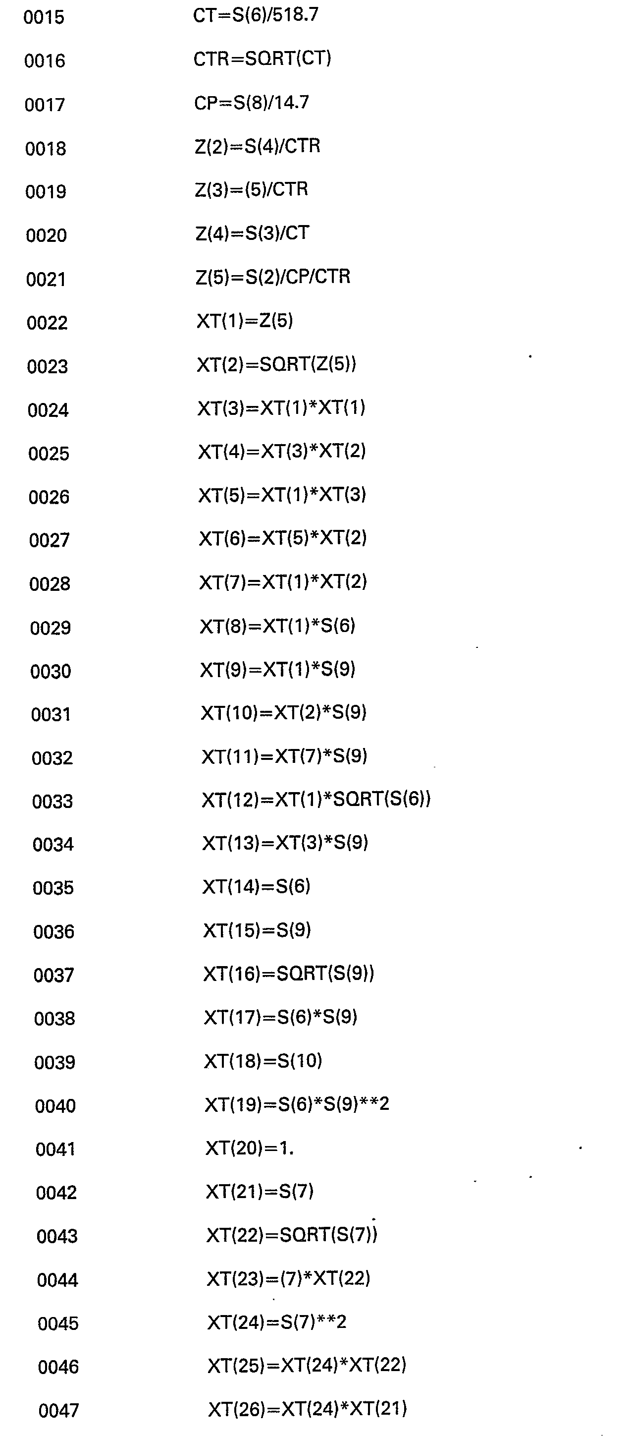


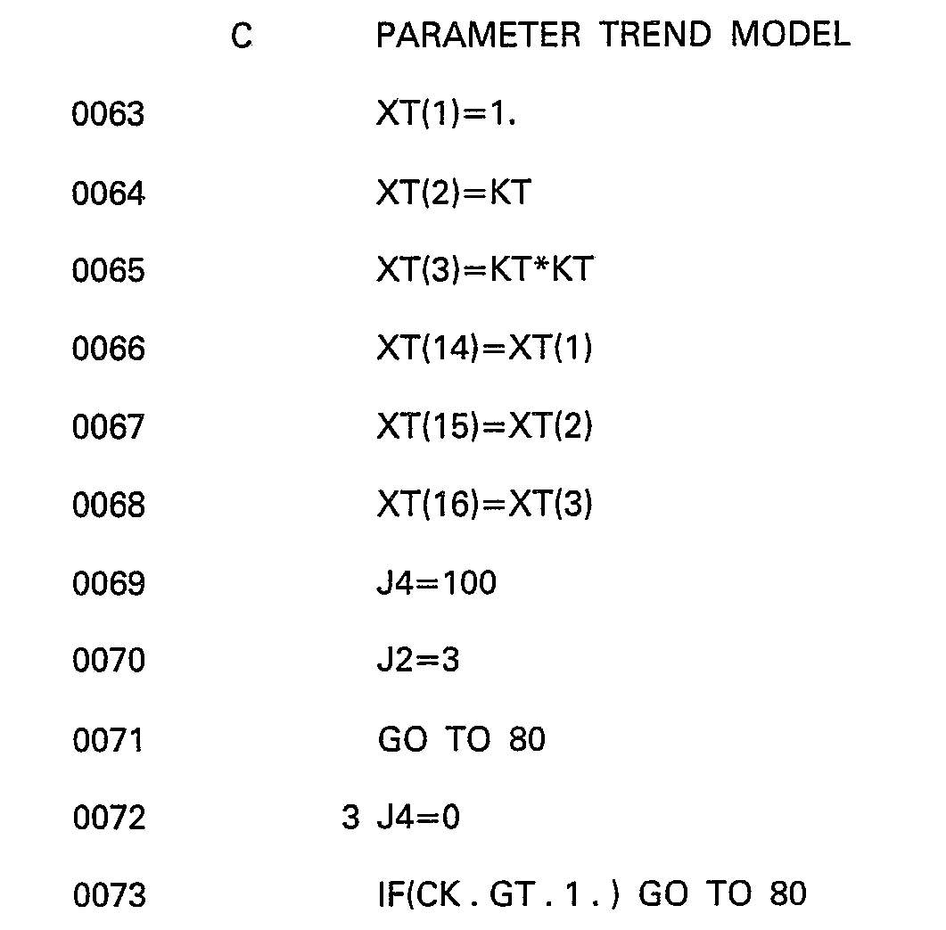


Claims (11)
characterized by
and
and


and,


and


and


Applications Claiming Priority (1)
| Application Number | Priority Date | Filing Date | Title |
|---|---|---|---|
| PCT/US1980/000447 WO1981003079A1 (en) | 1980-04-22 | 1980-04-22 | Real-time performance monitoring of gas turbine engines |
Publications (3)
| Publication Number | Publication Date |
|---|---|
| EP0050610A1 EP0050610A1 (en) | 1982-05-05 |
| EP0050610A4 EP0050610A4 (en) | 1984-04-24 |
| EP0050610B1 true EP0050610B1 (en) | 1986-12-30 |
Family
ID=22154294
Family Applications (1)
| Application Number | Title | Priority Date | Filing Date |
|---|---|---|---|
| EP19800900964 Expired EP0050610B1 (en) | 1980-04-22 | 1980-04-22 | Real-time performance monitoring of gas turbine engines |
Country Status (3)
| Country | Link |
|---|---|
| EP (1) | EP0050610B1 (en) |
| DE (1) | DE3071876D1 (en) |
| WO (1) | WO1981003079A1 (en) |
Cited By (4)
| Publication number | Priority date | Publication date | Assignee | Title |
|---|---|---|---|---|
| US8751423B2 (en) | 2010-11-30 | 2014-06-10 | General Electric Company | Turbine performance diagnostic system and methods |
| US9091616B2 (en) | 2013-06-06 | 2015-07-28 | Honeywell International Inc. | Engine operations support systems and methods for reducing fuel flow |
| US9317249B2 (en) | 2012-12-06 | 2016-04-19 | Honeywell International Inc. | Operations support systems and methods for calculating and evaluating turbine temperatures and health |
| US9376983B2 (en) | 2012-11-30 | 2016-06-28 | Honeywell International Inc. | Operations support systems and methods with acoustics evaluation and control |
Families Citing this family (10)
| Publication number | Priority date | Publication date | Assignee | Title |
|---|---|---|---|---|
| IN157898B (en) * | 1982-03-22 | 1986-07-19 | Babcock & Wilcox Co | |
| EP0121624A3 (en) * | 1982-10-22 | 1986-08-27 | British Aerospace Public Limited Company | Aircraft maintenance |
| US8417410B2 (en) | 2008-12-23 | 2013-04-09 | Honeywell International Inc. | Operations support systems and methods with power management |
| US8321118B2 (en) | 2008-12-23 | 2012-11-27 | Honeywell International Inc. | Operations support systems and methods with power assurance |
| US7801695B2 (en) | 2008-12-23 | 2010-09-21 | Honeywell International Inc. | Operations support systems and methods with model-based torque estimates |
| US8386121B1 (en) | 2009-09-30 | 2013-02-26 | The United States Of America As Represented By The Administrator Of National Aeronautics And Space Administration | Optimized tuner selection for engine performance estimation |
| US9243970B2 (en) | 2012-11-30 | 2016-01-26 | Pratt & Whitney Canada Corp. | Method and system for integrating gas turbine trim balancing system into electronic engine controls |
| FR3011946B1 (en) * | 2013-10-11 | 2016-07-08 | Snecma | MONITORING AN AIRCRAFT ENGINE TO ANTICIPATE MAINTENANCE OPERATIONS |
| US10247032B2 (en) | 2017-03-28 | 2019-04-02 | Honeywell International Inc. | Gas turbine engine and test cell real-time diagnostic fault detection and corrective action system and method |
| US11158140B2 (en) * | 2019-03-19 | 2021-10-26 | General Electric Company | Signal response monitoring for turbine engines |
Family Cites Families (6)
| Publication number | Priority date | Publication date | Assignee | Title |
|---|---|---|---|---|
| US3731070A (en) * | 1971-04-27 | 1973-05-01 | United Aircraft Corp | Gas turbine engine analyzer |
| US3750465A (en) * | 1971-09-09 | 1973-08-07 | Howell Instruments | Engine performance indicator |
| JPS5444161B2 (en) * | 1973-09-08 | 1979-12-24 | ||
| GB1502184A (en) * | 1974-07-05 | 1978-02-22 | Sperry Rand Corp | Automatic flight control systems |
| CH607474A5 (en) * | 1976-11-12 | 1978-12-29 | Ibm | |
| US4128005A (en) * | 1977-06-16 | 1978-12-05 | Sun Electric Corporation | Automated engine component diagnostic techniques |
-
1980
- 1980-04-22 EP EP19800900964 patent/EP0050610B1/en not_active Expired
- 1980-04-22 DE DE8080900964T patent/DE3071876D1/en not_active Expired
- 1980-04-22 WO PCT/US1980/000447 patent/WO1981003079A1/en not_active Ceased
Cited By (4)
| Publication number | Priority date | Publication date | Assignee | Title |
|---|---|---|---|---|
| US8751423B2 (en) | 2010-11-30 | 2014-06-10 | General Electric Company | Turbine performance diagnostic system and methods |
| US9376983B2 (en) | 2012-11-30 | 2016-06-28 | Honeywell International Inc. | Operations support systems and methods with acoustics evaluation and control |
| US9317249B2 (en) | 2012-12-06 | 2016-04-19 | Honeywell International Inc. | Operations support systems and methods for calculating and evaluating turbine temperatures and health |
| US9091616B2 (en) | 2013-06-06 | 2015-07-28 | Honeywell International Inc. | Engine operations support systems and methods for reducing fuel flow |
Also Published As
| Publication number | Publication date |
|---|---|
| WO1981003079A1 (en) | 1981-10-29 |
| DE3071876D1 (en) | 1987-02-05 |
| EP0050610A1 (en) | 1982-05-05 |
| EP0050610A4 (en) | 1984-04-24 |
Similar Documents
| Publication | Publication Date | Title |
|---|---|---|
| US4215412A (en) | Real time performance monitoring of gas turbine engines | |
| US20250320832A1 (en) | Machine learned aero-thermodynamic engine inlet condition synthesis | |
| Doel | TEMPER—a gas-path analysis tool for commercial jet engines | |
| US7734400B2 (en) | Fault detection system and method using augmented data and fuzzy logic | |
| EP1811133B1 (en) | Control system with sensor diagnostics using a quality parameter model | |
| EP1790838B1 (en) | Model-based iterative estimation of gas turbine engine component qualities | |
| WO1981003079A1 (en) | Real-time performance monitoring of gas turbine engines | |
| US7058556B2 (en) | Adaptive aero-thermodynamic engine model | |
| US6909960B2 (en) | Method for performing gas turbine performance diagnostics | |
| US4630189A (en) | System for determining abnormal plant operation based on whiteness indexes | |
| US5067099A (en) | Methods and apparatus for monitoring system performance | |
| US20080201104A1 (en) | Monitoring a degrading system | |
| GB2211965A (en) | Data processing systems | |
| GB1597129A (en) | Gas turbine engine control system | |
| Doel | The role for expert systems in commercial gas turbine engine monitoring | |
| US5680310A (en) | Method and apparatus for sensing a steady state engine condition using a trending algorithm | |
| Doel | TEMPER: A gas-path analysis tool for commercial jet engines | |
| EP4345258A1 (en) | Systems and methods for determining gas turbine engine temperatures | |
| Wang et al. | Shock-loading-based reliability modeling with dependent degradation processes and random shocks | |
| Fentaye et al. | Sensor fault/failure correction and missing sensor replacement for enhanced real-time gas turbine diagnostics | |
| Panov et al. | Application of Digital Twin Technology on Simulation and Optimization of Prime Movers in Energy Systems | |
| Bushman et al. | In-flight performance diagnostic capability of an adaptive engine model | |
| Gorinevsky et al. | Model-based diagnostics for small-scale turbomachines | |
| EP4549719A1 (en) | System and method for turbine engine parameter synthesis | |
| Goebel | Decision forgetting and decision smoothing for diagnostic decision fusion in systems with redundant information |
Legal Events
| Date | Code | Title | Description |
|---|---|---|---|
| PUAI | Public reference made under article 153(3) epc to a published international application that has entered the european phase |
Free format text: ORIGINAL CODE: 0009012 |
|
| 17P | Request for examination filed |
Effective date: 19811216 |
|
| AK | Designated contracting states |
Kind code of ref document: A1 Designated state(s): AT CH DE FR GB LU NL SE |
|
| GRAA | (expected) grant |
Free format text: ORIGINAL CODE: 0009210 |
|
| AK | Designated contracting states |
Kind code of ref document: B1 Designated state(s): DE FR GB NL SE |
|
| PG25 | Lapsed in a contracting state [announced via postgrant information from national office to epo] |
Ref country code: SE Effective date: 19861231 |
|
| ET | Fr: translation filed | ||
| REF | Corresponds to: |
Ref document number: 3071876 Country of ref document: DE Date of ref document: 19870205 |
|
| PLBE | No opposition filed within time limit |
Free format text: ORIGINAL CODE: 0009261 |
|
| STAA | Information on the status of an ep patent application or granted ep patent |
Free format text: STATUS: NO OPPOSITION FILED WITHIN TIME LIMIT |
|
| 26N | No opposition filed | ||
| PGFP | Annual fee paid to national office [announced via postgrant information from national office to epo] |
Ref country code: GB Payment date: 19900404 Year of fee payment: 11 |
|
| PGFP | Annual fee paid to national office [announced via postgrant information from national office to epo] |
Ref country code: FR Payment date: 19900427 Year of fee payment: 11 |
|
| PGFP | Annual fee paid to national office [announced via postgrant information from national office to epo] |
Ref country code: NL Payment date: 19900430 Year of fee payment: 11 |
|
| PGFP | Annual fee paid to national office [announced via postgrant information from national office to epo] |
Ref country code: DE Payment date: 19900531 Year of fee payment: 11 |
|
| PG25 | Lapsed in a contracting state [announced via postgrant information from national office to epo] |
Ref country code: GB Effective date: 19910422 |
|
| PG25 | Lapsed in a contracting state [announced via postgrant information from national office to epo] |
Ref country code: NL Effective date: 19911101 |
|
| NLV4 | Nl: lapsed or anulled due to non-payment of the annual fee | ||
| GBPC | Gb: european patent ceased through non-payment of renewal fee | ||
| PG25 | Lapsed in a contracting state [announced via postgrant information from national office to epo] |
Ref country code: FR Effective date: 19911230 |
|
| PG25 | Lapsed in a contracting state [announced via postgrant information from national office to epo] |
Ref country code: DE Effective date: 19920201 |
|
| REG | Reference to a national code |
Ref country code: FR Ref legal event code: ST |