EP0049908B1 - Aerial power transmission system - Google Patents
Aerial power transmission system Download PDFInfo
- Publication number
- EP0049908B1 EP0049908B1 EP81108520A EP81108520A EP0049908B1 EP 0049908 B1 EP0049908 B1 EP 0049908B1 EP 81108520 A EP81108520 A EP 81108520A EP 81108520 A EP81108520 A EP 81108520A EP 0049908 B1 EP0049908 B1 EP 0049908B1
- Authority
- EP
- European Patent Office
- Prior art keywords
- power transmission
- cable
- transmission system
- insulator
- lightning arrestor
- Prior art date
- Legal status (The legal status is an assumption and is not a legal conclusion. Google has not performed a legal analysis and makes no representation as to the accuracy of the status listed.)
- Expired
Links
Images

Classifications
-
- H—ELECTRICITY
- H01—ELECTRIC ELEMENTS
- H01C—RESISTORS
- H01C7/00—Non-adjustable resistors formed as one or more layers or coatings; Non-adjustable resistors made from powdered conducting material or powdered semi-conducting material with or without insulating material
- H01C7/10—Non-adjustable resistors formed as one or more layers or coatings; Non-adjustable resistors made from powdered conducting material or powdered semi-conducting material with or without insulating material voltage responsive, i.e. varistors
- H01C7/12—Overvoltage protection resistors; Arresters
-
- H—ELECTRICITY
- H01—ELECTRIC ELEMENTS
- H01B—CABLES; CONDUCTORS; INSULATORS; SELECTION OF MATERIALS FOR THEIR CONDUCTIVE, INSULATING OR DIELECTRIC PROPERTIES
- H01B17/00—Insulators or insulating bodies characterised by their form
- H01B17/42—Means for obtaining improved distribution of voltage; Protection against arc discharges
-
- H—ELECTRICITY
- H02—GENERATION; CONVERSION OR DISTRIBUTION OF ELECTRIC POWER
- H02G—INSTALLATION OF ELECTRIC CABLES OR LINES, OR OF COMBINED OPTICAL AND ELECTRIC CABLES OR LINES
- H02G7/00—Overhead installations of electric lines or cables
Definitions
- the present invention relates to an aerial power transmission system in accordance with the preamble of the main claim.
- a system is known from DE-A-2 361 204.
- each one of three phase power cables must be supported by separate arms of the steel towers. Therefore, the costs for the steel towers are high.
- DE-A-2 339 417 it is already known to jointly suspend three cables in a triangular configuration with conventional long trunk insulators therebetween. This arrangement requires somewhat less space. However, this triangular arrangement requires rather complicated means for the suspension and for the mutual insulation of the cables.
- Figure 1 and 2 show an aerial power transmission system wherein the reference numeral 1 designates a steel tower; 2 designates an aerial ground wire suspended on the top of the steel tower; 31, 32 and 33 designate power transmission cables in upper, middle and lower phases which are supported on the steel tower.
- the power transmission cables 31 to 33 in different phases are separately supported by different arms on the steel tower 1.
- the insulator-lightning arresters are connected between the cables 31 to 33 to support the cables whereby smaller size steel towers 1 can be used.
- two insulator-lightning arresters 5 having the structure of Figure 5 are connected in series between the cables 31 to 33 while a long trunk insulator 7 having arc horn type lightning arrester is connected in series with the arresters 5 and between the upper cable 31 and the arm of the steel tower 1.
- the insulator-lightning arrester 5 has a non-linear characteristic for reducing an abnormal voltage between the phases of the cables to a suitable voltage value. Thus, a mutual short-circuit is not caused in case of lightning.
- the spaces between the cables 31 to 33 in different phases can be narrower and the number of the arms on the steel tower can be reduced from three arms to one arm, so that the steel tower can be smaller.
- FIG. 3 The equivalent circuit of the system of Figure 1 is shown in Figure 3.
- a conventional long trunk insulator 7 having arc horn type lightning arrester is connected between the upper cable 31 and the tower whereby the flashover to the ground is not reduced as compared with the conventional system but the mutual short-circuit is prevented and a height of the steel tower can be decreased.
- Figure 2 shows the other embodiment of the present invention, wherein the insulator-lightning arrester 5 shown in Figure 5 is used for supporting the cable 31 in the upper phase on the tower 1.
- the number of the circuits in the composite system can be increased.
- the embodiments have been illustrated for the use of one long trunk insulator or one insulator-lightning arrester. However, it is possible to connect the insulators or the insulator-lightning arresters in series as desired in the case of high voltage such as a super-high voltage system.
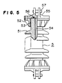
- the lightning arrester 5 comprises a lightning arrester element 54 made of sintered product of a main component of zinc oxide held inside a hollow long trunk insulator 51.
Landscapes
- Engineering & Computer Science (AREA)
- Microelectronics & Electronic Packaging (AREA)
- Power Engineering (AREA)
- Physics & Mathematics (AREA)
- Electromagnetism (AREA)
- Suspension Of Electric Lines Or Cables (AREA)
- Insulators (AREA)
- Emergency Protection Circuit Devices (AREA)
Description
- The present invention relates to an aerial power transmission system in accordance with the preamble of the main claim. Such a system is known from DE-A-2 361 204. In such a system each one of three phase power cables must be supported by separate arms of the steel towers. Therefore, the costs for the steel towers are high. From DE-A-2 339 417 it is already known to jointly suspend three cables in a triangular configuration with conventional long trunk insulators therebetween. This arrangement requires somewhat less space. However, this triangular arrangement requires rather complicated means for the suspension and for the mutual insulation of the cables.
- Therefore, it is the problem of the present invention to provide an improved aerial power transmission system which has relatively small steel towers and small spaces between the cables and which nevertheless prevents the reverse flashover phenomenon.
- This problem is solved by the aerial power transmission system of claim 1.
- Figures 1 and 2 show the embodiments of the aerial power transmission system of the present invention.
- Figures 3 and 4 show diagrams of equivalent circuit of the embodiments of Figures 1 and 2, respectively.
- Figure 5 shows a partial sectional view of an insulator containing a lightning arrester.
- Figure 1 and 2 show an aerial power transmission system wherein the reference numeral 1 designates a steel tower; 2 designates an aerial ground wire suspended on the top of the steel tower; 31, 32 and 33 designate power transmission cables in upper, middle and lower phases which are supported on the steel tower.
- In conventional power transmission systems, the
power transmission cables 31 to 33 in different phases are separately supported by different arms on the steel tower 1. On the other hand, in the embodiments of Figures 1 and 2, the insulator-lightning arresters are connected between thecables 31 to 33 to support the cables whereby smaller size steel towers 1 can be used. - In the embodiment of Figure 1, two insulator-
lightning arresters 5 having the structure of Figure 5 are connected in series between thecables 31 to 33 while along trunk insulator 7 having arc horn type lightning arrester is connected in series with thearresters 5 and between theupper cable 31 and the arm of the steel tower 1. The insulator-lightning arrester 5 has a non-linear characteristic for reducing an abnormal voltage between the phases of the cables to a suitable voltage value. Thus, a mutual short-circuit is not caused in case of lightning. - The spaces between the
cables 31 to 33 in different phases can be narrower and the number of the arms on the steel tower can be reduced from three arms to one arm, so that the steel tower can be smaller. - The equivalent circuit of the system of Figure 1 is shown in Figure 3. In this embodiment, a conventional
long trunk insulator 7 having arc horn type lightning arrester is connected between theupper cable 31 and the tower whereby the flashover to the ground is not reduced as compared with the conventional system but the mutual short-circuit is prevented and a height of the steel tower can be decreased. - Figure 2 shows the other embodiment of the present invention, wherein the insulator-
lightning arrester 5 shown in Figure 5 is used for supporting thecable 31 in the upper phase on the tower 1. - The equivalent circuit of the system of Figure 2 is shown in Figure 4. In accordance with the system of Figure 2, the protection of the cables between phases and to the ground can be attained to prevent completely the lightning damage and the height of the steel towers can be decreased.
- Sometimes, a composite aerial power transmission system with many power transmission cables for different voltages is supported on the same steel towers.
- Thus, when the height of the steel towers is not reduced, the number of the circuits in the composite system can be increased.
- The embodiments have been illustrated for the use of one long trunk insulator or one insulator-lightning arrester. However, it is possible to connect the insulators or the insulator-lightning arresters in series as desired in the case of high voltage such as a super-high voltage system.
- As shown in Figure 5, the
lightning arrester 5 comprises alightning arrester element 54 made of sintered product of a main component of zinc oxide held inside a hollowlong trunk insulator 51. Thereference numeral 52 designates a flange; 53 designates a cement bonded part for bonding theflange 52 to thelong trunk insulator 51; 55 designates a metal cover; 56 designates a packing for shielding; and 57 designates a pin for a connecting fitting. When thearrester 5 is used in the power transmission system, thepower transmission cables 31 to 33 are protected by the lightning arrester device whereby the lightning flashover and the lightning reverse flashover from the aerial ground wire 2 can be prevented. However, when due to low strength it is not suitable to support thepower transmission cables 31 to 33 by thearresters 5 alone, it is possible to connect thearresters 5 between the steel tower 1 and thepower transmission cables 31 to 33 in parallel to conventional long trunk insulators.
Claims (7)
Applications Claiming Priority (2)
| Application Number | Priority Date | Filing Date | Title |
|---|---|---|---|
| JP31294/78 | 1978-03-17 | ||
| JP53031294A JPS593092B2 (en) | 1978-03-17 | 1978-03-17 | Lightning-resistant overhead power transmission line equipment |
Related Parent Applications (1)
| Application Number | Title | Priority Date | Filing Date |
|---|---|---|---|
| EP79100797.4 Division | 1979-03-15 |
Publications (2)
| Publication Number | Publication Date |
|---|---|
| EP0049908A1 EP0049908A1 (en) | 1982-04-21 |
| EP0049908B1 true EP0049908B1 (en) | 1987-02-04 |
Family
ID=12327276
Family Applications (2)
| Application Number | Title | Priority Date | Filing Date |
|---|---|---|---|
| EP81108520A Expired EP0049908B1 (en) | 1978-03-17 | 1979-03-15 | Aerial power transmission system |
| EP79100797A Withdrawn EP0004350A1 (en) | 1978-03-17 | 1979-03-15 | Aerial power transmission system |
Family Applications After (1)
| Application Number | Title | Priority Date | Filing Date |
|---|---|---|---|
| EP79100797A Withdrawn EP0004350A1 (en) | 1978-03-17 | 1979-03-15 | Aerial power transmission system |
Country Status (8)
| Country | Link |
|---|---|
| US (1) | US4270160A (en) |
| EP (2) | EP0049908B1 (en) |
| JP (1) | JPS593092B2 (en) |
| BR (1) | BR7901636A (en) |
| CA (1) | CA1125841A (en) |
| ES (1) | ES478746A1 (en) |
| IN (1) | IN151774B (en) |
| MX (1) | MX147312A (en) |
Families Citing this family (7)
| Publication number | Priority date | Publication date | Assignee | Title |
|---|---|---|---|---|
| US4467387A (en) * | 1982-09-30 | 1984-08-21 | General Electric Company | Combination strut insulator and lightning arrester |
| NO171139C (en) * | 1986-01-29 | 1993-01-27 | Bowthorpe Emp Ltd | ELECTRICAL TRANSIENT STOPPERS / DERIVERS |
| JPH04294083A (en) * | 1991-03-25 | 1992-10-19 | Ngk Insulators Ltd | Lighting protective insulator device |
| US20030034713A1 (en) * | 2001-08-20 | 2003-02-20 | Weber Warren D. | Supplemental electric power generator and system |
| DE102017215127A1 (en) * | 2017-08-30 | 2018-10-11 | Siemens Aktiengesellschaft | Arrangement for power transmission |
| CN107742881B (en) * | 2017-11-14 | 2024-03-08 | 张京伦 | A virtual positive electrode induced lightning protection line lightning protection device on high-voltage DC overhead transmission lines |
| CN114336179B (en) * | 2021-12-31 | 2023-11-21 | 国网河南省电力公司周口供电公司 | Lightning-proof broken line protection device for shielding, insulating and isolating 10kV overhead insulated line |
Family Cites Families (11)
| Publication number | Priority date | Publication date | Assignee | Title |
|---|---|---|---|---|
| US3371144A (en) * | 1968-02-27 | Westinghouse Electric Corp | Transmission-line lightning-proofing structures | |
| US1937296A (en) * | 1931-05-05 | 1933-11-28 | Sporn Philip | Transmission line insulator system |
| US2539749A (en) * | 1946-11-27 | 1951-01-30 | Mcgraw Electric Co | Open type valve arrester |
| FR1326465A (en) * | 1962-03-26 | 1963-05-10 | Cie Generale Electro Ceramique | Device for protecting insulators against electric arcs |
| US3259762A (en) * | 1963-04-16 | 1966-07-05 | John E Skuderna | Electrostatic induction power supply |
| US3339116A (en) * | 1965-03-08 | 1967-08-29 | Ohio Brass Co | Line support insulator with discharge means |
| US3693053A (en) * | 1971-10-29 | 1972-09-19 | Gen Electric | Metal oxide varistor polyphase transient voltage suppression |
| US3805114A (en) * | 1972-03-01 | 1974-04-16 | Matsushita Electric Industrial Co Ltd | Voltage-nonlinear resistors |
| DE2339417C3 (en) * | 1973-08-03 | 1980-08-21 | Brown, Boveri & Cie Ag, 6800 Mannheim | Suspension chain for phase ropes on a cable pole |
| DE2361204C3 (en) * | 1973-12-06 | 1978-11-23 | Siemens Ag, 1000 Berlin Und 8000 Muenchen | Electrical high-voltage device with insulating bodies |
| US4161012A (en) * | 1977-03-02 | 1979-07-10 | Joslyn Mfg. And Supply Co. | High voltage protection apparatus |
-
1978
- 1978-03-17 JP JP53031294A patent/JPS593092B2/en not_active Expired
-
1979
- 1979-03-07 IN IN217/CAL/79A patent/IN151774B/en unknown
- 1979-03-14 MX MX176927A patent/MX147312A/en unknown
- 1979-03-15 EP EP81108520A patent/EP0049908B1/en not_active Expired
- 1979-03-15 EP EP79100797A patent/EP0004350A1/en not_active Withdrawn
- 1979-03-16 BR BR7901636A patent/BR7901636A/en unknown
- 1979-03-16 CA CA323,677A patent/CA1125841A/en not_active Expired
- 1979-03-16 ES ES478746A patent/ES478746A1/en not_active Expired
- 1979-03-16 US US06/021,175 patent/US4270160A/en not_active Expired - Lifetime
Also Published As
| Publication number | Publication date |
|---|---|
| EP0004350A1 (en) | 1979-10-03 |
| ES478746A1 (en) | 1979-08-01 |
| EP0049908A1 (en) | 1982-04-21 |
| MX147312A (en) | 1982-11-10 |
| CA1125841A (en) | 1982-06-15 |
| US4270160A (en) | 1981-05-26 |
| IN151774B (en) | 1983-07-30 |
| JPS54122897A (en) | 1979-09-22 |
| BR7901636A (en) | 1979-10-16 |
| JPS593092B2 (en) | 1984-01-23 |
Similar Documents
| Publication | Publication Date | Title |
|---|---|---|
| US4270160A (en) | Lightning resistive device in aerial power transmission system | |
| US4340924A (en) | Grading means for high voltage metal enclosed gas insulated surge arresters | |
| CY1295A (en) | Surge diverter/arrester | |
| US4203143A (en) | Protective device | |
| US4369480A (en) | Overvoltage arrester including a column of arrester elements and shielding therefor | |
| JP3866291B2 (en) | Gas insulated high voltage semiconductor valve device | |
| US4774622A (en) | Connecting apparatus for lightning arresters for overhead transmission lines | |
| US4754363A (en) | Metal-encapsulated gas-insulated high-voltage installation with an overvoltage arrester | |
| US4258407A (en) | Lightning arrester device for power transmission line | |
| JPH0729665A (en) | Lightning arrester and assembling method thereof | |
| US3004117A (en) | Air-break disconnecting switches | |
| JPS5923050B2 (en) | Lightning resistant bushing | |
| JPH06113434A (en) | Interphase spacer | |
| JPS59171428A (en) | Open cutout with nonlinear resistance element | |
| US5539607A (en) | Tank-shape arrester | |
| JP3119938B2 (en) | Tank type surge arrester | |
| EP1138050B2 (en) | Transmission line-mounted surge arrester with a stabilizing device | |
| US4204239A (en) | Abnormal voltage protection device | |
| JPS594551Y2 (en) | archorn | |
| JPS592362B2 (en) | Lightning arrester | |
| EP0004351A1 (en) | Lightning arrester device | |
| US1937296A (en) | Transmission line insulator system | |
| JPS596111Y2 (en) | transformer protection device | |
| JPH022034Y2 (en) | ||
| JPH0714707A (en) | Arrester for power transmission |
Legal Events
| Date | Code | Title | Description |
|---|---|---|---|
| PUAI | Public reference made under article 153(3) epc to a published international application that has entered the european phase |
Free format text: ORIGINAL CODE: 0009012 |
|
| AC | Divisional application: reference to earlier application |
Ref document number: 4350 Country of ref document: EP |
|
| AK | Designated contracting states |
Designated state(s): CH DE FR GB IT SE |
|
| 17P | Request for examination filed |
Effective date: 19820507 |
|
| GRAA | (expected) grant |
Free format text: ORIGINAL CODE: 0009210 |
|
| AC | Divisional application: reference to earlier application |
Ref document number: 4350 Country of ref document: EP |
|
| AK | Designated contracting states |
Kind code of ref document: B1 Designated state(s): CH DE FR GB IT SE |
|
| ITF | It: translation for a ep patent filed | ||
| REF | Corresponds to: |
Ref document number: 2967647 Country of ref document: DE Date of ref document: 19870312 |
|
| ET | Fr: translation filed | ||
| PLBE | No opposition filed within time limit |
Free format text: ORIGINAL CODE: 0009261 |
|
| STAA | Information on the status of an ep patent application or granted ep patent |
Free format text: STATUS: NO OPPOSITION FILED WITHIN TIME LIMIT |
|
| 26N | No opposition filed | ||
| ITTA | It: last paid annual fee | ||
| EAL | Se: european patent in force in sweden |
Ref document number: 81108520.8 |
|
| REG | Reference to a national code |
Ref country code: GB Ref legal event code: 746 Effective date: 19951026 |
|
| PGFP | Annual fee paid to national office [announced via postgrant information from national office to epo] |
Ref country code: GB Payment date: 19960306 Year of fee payment: 18 |
|
| REG | Reference to a national code |
Ref country code: FR Ref legal event code: D6 |
|
| PGFP | Annual fee paid to national office [announced via postgrant information from national office to epo] |
Ref country code: DE Payment date: 19960313 Year of fee payment: 18 |
|
| PGFP | Annual fee paid to national office [announced via postgrant information from national office to epo] |
Ref country code: SE Payment date: 19960315 Year of fee payment: 18 Ref country code: FR Payment date: 19960315 Year of fee payment: 18 |
|
| PGFP | Annual fee paid to national office [announced via postgrant information from national office to epo] |
Ref country code: CH Payment date: 19960325 Year of fee payment: 18 |
|
| ITPR | It: changes in ownership of a european patent |
Owner name: OFFERTA DI LICENZA AL PUBBLICO |
|
| PG25 | Lapsed in a contracting state [announced via postgrant information from national office to epo] |
Ref country code: GB Effective date: 19970315 |
|
| PG25 | Lapsed in a contracting state [announced via postgrant information from national office to epo] |
Ref country code: SE Effective date: 19970316 |
|
| PG25 | Lapsed in a contracting state [announced via postgrant information from national office to epo] |
Ref country code: CH Effective date: 19970331 |
|
| GBPC | Gb: european patent ceased through non-payment of renewal fee |
Effective date: 19970315 |
|
| REG | Reference to a national code |
Ref country code: CH Ref legal event code: PL |
|
| PG25 | Lapsed in a contracting state [announced via postgrant information from national office to epo] |
Ref country code: FR Free format text: LAPSE BECAUSE OF NON-PAYMENT OF DUE FEES Effective date: 19971128 |
|
| PG25 | Lapsed in a contracting state [announced via postgrant information from national office to epo] |
Ref country code: DE Effective date: 19971202 |
|
| EUG | Se: european patent has lapsed |
Ref document number: 81108520.8 |
|
| REG | Reference to a national code |
Ref country code: FR Ref legal event code: ST |