EP0049208B1 - Magnetized conveyor chain element - Google Patents
Magnetized conveyor chain element Download PDFInfo
- Publication number
- EP0049208B1 EP0049208B1 EP81630057A EP81630057A EP0049208B1 EP 0049208 B1 EP0049208 B1 EP 0049208B1 EP 81630057 A EP81630057 A EP 81630057A EP 81630057 A EP81630057 A EP 81630057A EP 0049208 B1 EP0049208 B1 EP 0049208B1
- Authority
- EP
- European Patent Office
- Prior art keywords
- chain
- conveyor
- aperture
- article carrying
- insert member
- Prior art date
- Legal status (The legal status is an assumption and is not a legal conclusion. Google has not performed a legal analysis and makes no representation as to the accuracy of the status listed.)
- Expired
Links
Images

Classifications
-
- B—PERFORMING OPERATIONS; TRANSPORTING
- B65—CONVEYING; PACKING; STORING; HANDLING THIN OR FILAMENTARY MATERIAL
- B65G—TRANSPORT OR STORAGE DEVICES, e.g. CONVEYORS FOR LOADING OR TIPPING, SHOP CONVEYOR SYSTEMS OR PNEUMATIC TUBE CONVEYORS
- B65G17/00—Conveyors having an endless traction element, e.g. a chain, transmitting movement to a continuous or substantially-continuous load-carrying surface or to a series of individual load-carriers; Endless-chain conveyors in which the chains form the load-carrying surface
- B65G17/30—Details; Auxiliary devices
- B65G17/46—Means for holding or retaining the loads in fixed position on the load-carriers, e.g. magnetic
-
- B—PERFORMING OPERATIONS; TRANSPORTING
- B65—CONVEYING; PACKING; STORING; HANDLING THIN OR FILAMENTARY MATERIAL
- B65G—TRANSPORT OR STORAGE DEVICES, e.g. CONVEYORS FOR LOADING OR TIPPING, SHOP CONVEYOR SYSTEMS OR PNEUMATIC TUBE CONVEYORS
- B65G2201/00—Indexing codes relating to handling devices, e.g. conveyors, characterised by the type of product or load being conveyed or handled
- B65G2201/02—Articles
Definitions
- the present invention relates to a conveyor chain element comprising a substantially flat article carrying portion, at least one leg depending from said article carrying portion and having an eye therein for insertion of a pin and at least one flat resilient magnetic member mounted on each article carrying portion to attract ferromagnetic articles to be conveyed.
- a conveyor chain element of this type is known from US-A-3.871.510.
- Products being conveyed may be of several different types and made of various materials.
- attempts have been made to provide some type of magnetic attraction between the products and the conveyor.
- prior attempts to provide this magnetic attraction have included mounting magnets beneath the conveyor chain to establish a magnetic field in the area above the conveyor chain where the transported products are located. While being relatively successful as far as improving the stability of the products on the conveyors in both horizontal and inclined situations, these previous attempts have several serious drawbacks. Provision of magnets beneath the conveyor chain results in the chain being pulled toward its wear strips by attraction of the product through the chain. This increases the frictional drag of the chain on the wear strips resulting in increased wear of the chain links and other conveyor members and increased power requirements to drive the chain. Also, pulsation of the conveyor has resulted in these systems. These prior attempts have also proved to be very expensive.
- the material from which the chain links 10 are made varies depending upon the environment in which the conveyor will operate. In many applications, metallic links are preferable while in other applications nonmetallic or polymeric links are preferred.
- the present invention may be utilized with either type of link material. Additionally, snap-on top plates for attachment to a conventional roller chain may be magnetized in accordance with the principles of the present invention.
- the holes 19 in the articles carrying portion 12 of the links 10 are recessed near the upper surface of the link 10 so that the insert members 20 when positioned in the holes 19 will be flush with that surface.
- the magnetized insert member 20 comprises a polymeric resin material such as a polyester or polyurethane with a magnetic filler material such as barium ferrite interspersed in the resin during the molding process.
- the magnetic filler material may be magnetized either during the molding process to produce a relatively high energy magnet or after the molding process to produce a relatively lower energy magnet. While high energy magnets may be desirable in some situations, it is believed that low energy magnets will suffice in most cases resulting in less expensive equipment being required to mold the magnetized insert members 20.
- the size and quantity of magnetic insert members 20 required will vary depending upon the size, shape and weight of the articles being conveyed. In the present embodiment a variety of magnetic insert members 20 can be stocked and selectively supplied with the base chain links 10 according to the requirements of a particular conveying application.
- a conveyor 50 comprising a plurality of interconnected chain links 10 in conveying ferromagnetic articles 51 such as metal containers.
- the conveyor shown includes a transfer area 58 where articles 51 are guided from a first section of conveyor 45 to a second 46 by guide rails 52.
- a first set of two sprockets 53, 54 provides the drive means for the first conveyor section while a second set of two sprockets 55, 56 provides the drive means for the second conveyor section.
- guide rails 52 are provided to transfer the articles 51.
- neutralization of the magnetic field is normally not required to transfer the products 51.
- the transfer of articles 51 may be eased by neutralizing the magnetic attraction of the chain links 10 at the transfer area 58. Those same links will then regain their magnetic attraction after they pass the transfer area.
- the neutralizing is accomplished by providing a magnetizing coil 57 at the transfer area 58.
- a neutralizing coil 57 is positioned in the first conveyor section 45 before the transfer area 58.
- This coil 57 is electrically connected to produce a magnetic field having a polarity opposite to that of the magnetized chain links 10 as they pass through the coil 57.
- the coil 57 has a neutralizing effect on the magnetic field of the links 10 thereby allowing the conveyed articles 51 to more easily transfer from the first 45 to second 46 conveyor section.
- the links 10 then regain their magnetic attraction after passing the transfer area 58.
- a plate top conveyor chain 100 comprises a conventional roller chain 101 including some extended chain pins 102.
- the chain element or plate top attachment 103 includes an article carrying portion 104 with depending legs 105 having holes 106 therein for receiving the extended portions 102 of the pins thereby connecting the attachment 103 to the roller chain 101.
- the article carrying portion 104 includes a magnetized insert member 110 which fits into a hole 112 in the attachment 103.
- this embodiment of the plate top conveyor chain is identical to the conveyors previously described except that the conveyor is driven by sprockets designed for roller chain.
Landscapes
- Engineering & Computer Science (AREA)
- Mechanical Engineering (AREA)
- Chain Conveyers (AREA)
- Non-Mechanical Conveyors (AREA)
- Belt Conveyors (AREA)
- Injection Moulding Of Plastics Or The Like (AREA)
- Devices For Conveying Motion By Means Of Endless Flexible Members (AREA)
Description
- The present invention relates to a conveyor chain element comprising a substantially flat article carrying portion, at least one leg depending from said article carrying portion and having an eye therein for insertion of a pin and at least one flat resilient magnetic member mounted on each article carrying portion to attract ferromagnetic articles to be conveyed. A conveyor chain element of this type is known from US-A-3.871.510.
- In many industrial applications it is often desirable to convey articles from one location to another by means of a travelling article carrying conveyor chain which supports the articles being conveyed. In situations requiring the transport of relatively tall articles it is often necessary to stabilize the products on the conveyor chain by using attachments to the chain which support the conveyed products and minimize the possibility of product tippage. Similarly, in situations requiring the transport of articles up or down an incline it is typically necessary to provide conveyor chain attachments of one type or another to prevent the conveyed products from slipping on the inclined portion of the conveyor.
- Products being conveyed may be of several different types and made of various materials. In those circumstances where products are made from ferro magnetic materials attempts have been made to provide some type of magnetic attraction between the products and the conveyor. Generally, prior attempts to provide this magnetic attraction have included mounting magnets beneath the conveyor chain to establish a magnetic field in the area above the conveyor chain where the transported products are located. While being relatively successful as far as improving the stability of the products on the conveyors in both horizontal and inclined situations, these previous attempts have several serious drawbacks. Provision of magnets beneath the conveyor chain results in the chain being pulled toward its wear strips by attraction of the product through the chain. This increases the frictional drag of the chain on the wear strips resulting in increased wear of the chain links and other conveyor members and increased power requirements to drive the chain. Also, pulsation of the conveyor has resulted in these systems. These prior attempts have also proved to be very expensive.
- Additionally, other attempts, such as that shown in the hereinbefore mentioned US-A-3,871,510 have included attachment of magnets to the article carrying portion of the conveyor elements to impart magnetic properties to the elements. These attempts suffer from the drawbacks of being time consuming and difficult to assemble and also require storage of many additional component parts.
- The conveyor chain element of the present invention overcomes the drawbacks associated with presently known magnetic conveyors by providing chain elements easy to assemble and with magnetized article carrying portions providing the requisite magnetic field to attract the conveyed products to the chain without increasing the frictional drag of the chain on the conveyor wear strips.
- According to the invention the flat resilient magnetic member is in the form of an insert member positioned in an aperture formed in said article carrying portion and including a substantially flat top portion, a small-diameter central portion, and a tab portion, wherein said top and tab portions have a larger outside diameter than the smallest internal diameter of 'said aperture, such that said insert member may be inserted into said aperture by deforming said tab portion until it passes through the smallest internal diameter of said aperture so that said insert member may be retained in said aperture by the larger diameter tab and top portions.
- The insert member can be made from a polymeric material that is injection molded to the appropriate size and shaped to fit the hole in the chain element. Preferably, the insert member comprises a polymeric resin containing a ferro magnetic filler such as barium-ferrite in sufficient quantity to provide the desired magnetic characteristics.
- Although one embodiment of the invention can be used with metallic as well as nonmetallic elements, nonmetallic elements are preferred. Nonmetallic chain protects the conveyed articles from damage that can be caused by articles sliding along the chain during conveying.
- A conveyor using chain elements of the invention offers substantial advantages. Also, the insert members are easily assemblable with the article conveying portion. As previously mentioned, frictional drag of the conveyor elements against the conveyor wear strips is not increased because no additional forces are exerted on the elements. Additionally, means for selectively neutralizing the magnetic fields around the elements as they pass a transfer point along the conveyor may be provided to more easily strip the products from the conveyor.
- However, stripping of products from the conveyor can also be accomplished without neutralizing the magnetic field because less force is required to slide the product off the conveyor than is required to lift the product from the conveyor.
- Another benefit possible in a conveyor constructed of chain elements having magnetic inserts is to convey articles up and down relatively steep inclines without the use of special attachments to the chain elements. In such applications the conveyor chain has a tendency to raise as it makes the transition from its horizontal to inclined path. To counteract this tendency the portions of the wear strip at the juncture where the conveyor chain tends to raise may comprise a ferro magnetic strip to attract the chain to the strip thereby reducing the tendency of the chain to raise from its track.
- A more thorough understanding of the present invention will be gained by reading the following description of the preferred embodiments with reference to the accompanying drawings in which:
- Figure 1 is a perspective view of one embodiment of a chain element constructed according to the principles of the present invention,
- Figure 2 is a side view along line 2-2 of the chain element of Figure 1,
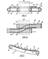
- Figure 3 is a side view of a conveyor constructed according to the principles of the present invention using the chain element of Figure 1,
- Figure 4 is a top view of the conveyor of Figure 3,
- Figure 5 is a side view of an inclined conveyor constructed in accordance with the principles of the present invention,
- Figure 6 is a perspective view of another embodiment of the present invention used with a snap-on attachment, and
- Figure 7 is a sectional view taken along the section 8-8 of Figure 6.
- Referring now to Figure 1, there is shown a
chain element 10 employing the principles of the present invention.Chain element 10 is in form of a chain link including an article carrying portion 12 and twolegs 14 integrally depending therefrom connecting theeyes 15 of the link. The twoeyes 15 at the leading edge and one eye 16 at the trailing edge of thelink 10 are formed so that the trailing eye 16 of onelink 10 fits between the twoeyes 15 on the leading edge of anadjacent link 10 to form a conveyor chain by connectingadjacent links 10 with chain pins in a conventional manner. The dependinglegs 14 preferably have outwardly extending projections ortabs 17 to engage wear strips on which the chain is supported in the conveying operation. - The material from which the
chain links 10 are made varies depending upon the environment in which the conveyor will operate. In many applications, metallic links are preferable while in other applications nonmetallic or polymeric links are preferred. The present invention may be utilized with either type of link material. Additionally, snap-on top plates for attachment to a conventional roller chain may be magnetized in accordance with the principles of the present invention. - The
chain link 10 of Figure 1 is shown as having two holes 19 in its article carrying portion 12. In each aperture 19 there is amagnetized insert member 20. The apertures 19 have a varying internal diameter. Theinsert members 20 are constructed with a varying outside diameter which permits the insert members to be placed in the holes 19 and locked in place. In the embodiment shown each insert member includes a large top surface, a smaller diameter central portion, and a sectioned tab portion 21 that is larger than the smallest internal diameter of aperture 19. When theinsert member 20 is inserted into aperture 19, the tab portion 21 is radially compressed until it passes through the smallest internal diameter portion of aperture 19. When the large diameter bottom portion 21 of theinsert member 20 has passed through the smallest part of hole 19, the tabs 21 return to their normal position. Thus, theinsert member 20 is secured in position by its large top and bottom portions, both of which are larger than the smallest diameter portion of aperture 19. While thelink 10 shown has twoinsert members 20, any desired number may be used. - The holes 19 in the articles carrying portion 12 of the
links 10 are recessed near the upper surface of thelink 10 so that theinsert members 20 when positioned in the holes 19 will be flush with that surface. - In accordance with known techniques, the
magnetized insert member 20 comprises a polymeric resin material such as a polyester or polyurethane with a magnetic filler material such as barium ferrite interspersed in the resin during the molding process. The magnetic filler material may be magnetized either during the molding process to produce a relatively high energy magnet or after the molding process to produce a relatively lower energy magnet. While high energy magnets may be desirable in some situations, it is believed that low energy magnets will suffice in most cases resulting in less expensive equipment being required to mold themagnetized insert members 20. - The size and quantity of
magnetic insert members 20 required will vary depending upon the size, shape and weight of the articles being conveyed. In the present embodiment a variety ofmagnetic insert members 20 can be stocked and selectively supplied with thebase chain links 10 according to the requirements of a particular conveying application. - It should be apparent that the particular shape of the
magnetized insert members 20 may vary without departing from the scope of the present invention. - As shown in Figure 3 and 4 a
conveyor 50 comprising a plurality ofinterconnected chain links 10 in conveying ferromagnetic articles 51 such as metal containers. The conveyor shown includes atransfer area 58 where articles 51 are guided from a first section ofconveyor 45 to a second 46 byguide rails 52. A first set of twosprockets 53, 54 provides the drive means for the first conveyor section while a second set of twosprockets 55, 56 provides the drive means for the second conveyor section. At an intermediate overlapping area of the two conveyorsections guide rails 52 are provided to transfer the articles 51. As previously stated, neutralization of the magnetic field is normally not required to transfer the products 51. - The transfer of articles 51 may be eased by neutralizing the magnetic attraction of the chain links 10 at the
transfer area 58. Those same links will then regain their magnetic attraction after they pass the transfer area. The neutralizing is accomplished by providing a magnetizingcoil 57 at thetransfer area 58. - As shown in the drawing a neutralizing
coil 57 is positioned in thefirst conveyor section 45 before thetransfer area 58. Thiscoil 57 is electrically connected to produce a magnetic field having a polarity opposite to that of themagnetized chain links 10 as they pass through thecoil 57. Thecoil 57 has a neutralizing effect on the magnetic field of thelinks 10 thereby allowing the conveyed articles 51 to more easily transfer from the first 45 to second 46 conveyor section. Thelinks 10 then regain their magnetic attraction after passing thetransfer area 58. - Referring now to Figure 5, there is shown an
inclined conveyor section 70 employingchain links 10 constructed according to the principles of the present invention. The chain links 10 are supported by and travel on nonmetallic low friction wear strips 71 and are driven in a conventional manner by a set ofsprockets - As the conveyed articles 51 proceed along with the
magnetized links 10 of theconveyor 70 theinclined portion 75 is encountered. At thetransition point 76 experience has demonstrated that the conveyor chain links 10 tend to raise up from the wear strips 71. In accordance with the principles of the present invention this tendency can be counteracted by providing a ferromagnetic portion ofwear strip 78 at the transition section of the conveyor between the horizontal 77 and inclined 75 portions of theconveyor 70. The attraction between themagnetized chain links 10 and theferromagnetic wear strip 78 counteracts the tendency of the conveyor chain to raise. - In another embodiment of the present invention shown in Figures 6 and 7, a plate
top conveyor chain 100 comprises aconventional roller chain 101 including some extended chain pins 102. The chain element or platetop attachment 103 includes anarticle carrying portion 104 with dependinglegs 105 havingholes 106 therein for receiving theextended portions 102 of the pins thereby connecting theattachment 103 to theroller chain 101. As previously described, thearticle carrying portion 104 includes amagnetized insert member 110 which fits into ahole 112 in theattachment 103. In operation this embodiment of the plate top conveyor chain is identical to the conveyors previously described except that the conveyor is driven by sprockets designed for roller chain.
Claims (2)
Applications Claiming Priority (2)
| Application Number | Priority Date | Filing Date | Title |
|---|---|---|---|
| US06/191,477 US4586601A (en) | 1980-09-26 | 1980-09-26 | Magnetized conveyor and chain links |
| US191477 | 1980-09-26 |
Related Child Applications (2)
| Application Number | Title | Priority Date | Filing Date |
|---|---|---|---|
| EP83630189A Division EP0109917A3 (en) | 1980-09-26 | 1981-09-23 | Magnetized conveyor chain element |
| EP83630189.5 Division-Into | 1981-09-23 |
Publications (2)
| Publication Number | Publication Date |
|---|---|
| EP0049208A1 EP0049208A1 (en) | 1982-04-07 |
| EP0049208B1 true EP0049208B1 (en) | 1984-12-27 |
Family
ID=22705659
Family Applications (2)
| Application Number | Title | Priority Date | Filing Date |
|---|---|---|---|
| EP81630057A Expired EP0049208B1 (en) | 1980-09-26 | 1981-09-23 | Magnetized conveyor chain element |
| EP83630189A Withdrawn EP0109917A3 (en) | 1980-09-26 | 1981-09-23 | Magnetized conveyor chain element |
Family Applications After (1)
| Application Number | Title | Priority Date | Filing Date |
|---|---|---|---|
| EP83630189A Withdrawn EP0109917A3 (en) | 1980-09-26 | 1981-09-23 | Magnetized conveyor chain element |
Country Status (10)
| Country | Link |
|---|---|
| US (1) | US4586601A (en) |
| EP (2) | EP0049208B1 (en) |
| JP (1) | JPS5790307A (en) |
| AU (2) | AU549218B2 (en) |
| BR (1) | BR8106147A (en) |
| CA (1) | CA1165714A (en) |
| DE (1) | DE3167962D1 (en) |
| DK (1) | DK152278C (en) |
| ES (1) | ES8301815A1 (en) |
| MX (1) | MX150940A (en) |
Families Citing this family (37)
| Publication number | Priority date | Publication date | Assignee | Title |
|---|---|---|---|---|
| JPS6138114U (en) * | 1984-08-09 | 1986-03-10 | 幸男 石田 | Vertical transfer device for canned goods, etc. |
| DE8530825U1 (en) * | 1985-10-31 | 1986-01-16 | Rexnord Kette GmbH & Co KG, 5240 Betzdorf | Curved chain conveyor |
| US4850542A (en) * | 1986-08-28 | 1989-07-25 | Isoreg Corporation | Winding apparatus utilizing magnetic carrier units |
| US5579897A (en) * | 1987-06-08 | 1996-12-03 | Saseb Bakery North America, Inc. | Magnetic conveyor system |
| US4972941A (en) * | 1987-06-08 | 1990-11-27 | Stewart Systems, Inc. | Continuous proofing and baking apparatus having magnetic conveyor system |
| US5147033A (en) * | 1987-06-08 | 1992-09-15 | Stewart Systems, Inc. | Continuous proofing and baking apparatus having magnetic conveyor system |
| US4836360A (en) * | 1987-06-08 | 1989-06-06 | Stewart Systems, Inc. | Continuous proofing and baking apparatus having magnetic conveyor system |
| US4946022A (en) * | 1989-08-23 | 1990-08-07 | Stewart Systems, Inc. | Article sorting switch |
| JPH0440016U (en) * | 1990-03-09 | 1992-04-06 | ||
| IT219317Z2 (en) * | 1990-03-20 | 1993-02-18 | Regina Sud Spa | PERFECTED CHAIN CONVEYOR |
| US5188216A (en) * | 1990-07-09 | 1993-02-23 | Smith Stephen R | Magnetic grid |
| US5150621A (en) * | 1990-11-01 | 1992-09-29 | Eastman Kodak Company | Apparatus for collecting samples of articles conveyed at high speed in consecutive order |
| US5299681A (en) * | 1991-04-30 | 1994-04-05 | Murata Manufacturing Co., Ltd. | Conveyor equipment |
| US5346060A (en) * | 1993-08-31 | 1994-09-13 | Precision Handling Devices, Inc. | Link assemblies which are interconnected to provide a self-tensioning conveyor belt |
| US5787891A (en) * | 1995-03-16 | 1998-08-04 | Sak; Robert | Method and apparatus for sampling cervical tissue |
| DE19856102C2 (en) * | 1998-12-04 | 2003-11-20 | Tyco Electronics Logistics Ag | Transport system for small components |
| US6305530B1 (en) | 2000-05-30 | 2001-10-23 | Habasit Ag | Module for a modular conveying belt |
| KR100615534B1 (en) * | 2000-06-28 | 2006-08-25 | 가부시키가이샤 이시노 세이사쿠쇼 | Circulating type food and drink transport apparatus |
| US6725883B2 (en) | 2001-06-05 | 2004-04-27 | Habasit Ag | Flat top open hinge module |
| US20030224198A1 (en) * | 2002-01-11 | 2003-12-04 | Nissan Technical Center North America, Inc. | Reusable masking device for sprayable bed liner |
| US6705460B2 (en) * | 2002-04-23 | 2004-03-16 | Laitram L.L.C. | Modular conveyor belt |
| US6913137B2 (en) | 2003-06-18 | 2005-07-05 | Turkington Apv Usa, Llc | Method of retrofitting magnetic guide to a grid |
| US7114614B2 (en) * | 2003-06-18 | 2006-10-03 | Turkington Apv Usa, Llc | Magnetic centerguide |
| US7762386B2 (en) * | 2006-11-10 | 2010-07-27 | Industrial Magnetics Incorporated | Magnet assembly for a conveyor system |
| EP2221143B1 (en) * | 2007-09-07 | 2013-11-13 | Tohoku Seiki Industries, Ltd. | Solar battery module transfer line |
| US20090267717A1 (en) * | 2008-04-24 | 2009-10-29 | Baskett Michael D | Magnetic Mat for Holding Surgical Instruments |
| JP5089743B2 (en) * | 2010-09-28 | 2012-12-05 | 株式会社椿本チエイン | Conveyor chain |
| JP5214761B2 (en) * | 2011-03-24 | 2013-06-19 | 株式会社椿本チエイン | Chain conveyor equipment |
| JP5165085B2 (en) * | 2011-06-06 | 2013-03-21 | 株式会社椿本チエイン | Chain conveyor equipment |
| JP5875116B2 (en) * | 2012-06-04 | 2016-03-02 | 株式会社椿本チエイン | Chain conveyor |
| CN105593144B (en) | 2013-09-30 | 2018-07-27 | 莱特拉姆有限责任公司 | Magnetic Conveyor Belt module |
| US10138065B2 (en) * | 2013-09-30 | 2018-11-27 | Laitram, L.L.C. | Magnetic conveyor belt module |
| US10494185B2 (en) * | 2015-09-10 | 2019-12-03 | AMF automation Technologies, LLC | Adjustable magnetic grid for conveyor system |
| BR112018015108B1 (en) * | 2016-02-01 | 2022-12-06 | Laitram, L.L.C | MAGNETIC CONVEYOR BELT MODULE |
| US9908710B2 (en) * | 2016-04-06 | 2018-03-06 | Laitram, L.L.C. | Magnetic conveyor belt module |
| DE102016107976A1 (en) * | 2016-04-29 | 2017-11-02 | Weber Maschinenbau Gmbh Breidenbach | Device for moving products |
| US12371280B2 (en) * | 2021-02-18 | 2025-07-29 | Laitram, L.L.C. | Hinged magnetic mover for a magnetic levitation conveyor |
Family Cites Families (10)
| Publication number | Priority date | Publication date | Assignee | Title |
|---|---|---|---|---|
| US2708022A (en) * | 1954-03-24 | 1955-05-10 | United States Steel Corp | Magnetic conveyor |
| US2806396A (en) * | 1954-05-06 | 1957-09-17 | George M Miller | Permanent magnet for use with socket wrenches, conveyor belts, extension tubes, and the like |
| US2911091A (en) * | 1955-04-07 | 1959-11-03 | Chain Belt Co | Plastic flat top conveyer |
| DE1099935B (en) * | 1958-09-24 | 1961-02-16 | Deutsche Edelstahlwerke Ag | Magnetic conveyor with an endless rubber or plastic conveyor belt |
| GB945887A (en) * | 1960-04-30 | 1964-01-08 | Rapid Magnetic Ltd | Conveying articles or material capable of being influenced by a magnet |
| DE1127795B (en) * | 1961-11-03 | 1962-04-12 | Konrad Grebe | Endless magnetic drive link chain for conveyor belts |
| US3669247A (en) * | 1971-03-17 | 1972-06-13 | Velten & Pulver | Conveyor system and attachments therefor |
| BE795352A (en) * | 1972-02-14 | 1973-05-29 | Rexnord Inc | FLAT TOP SIDE CHAIN, LOW FRICTION COEFFICIENT, FOR OBJECT HANDLING |
| US3871510A (en) * | 1973-04-19 | 1975-03-18 | Fmc Corp | Magnetic conveyor structure |
| US3992689A (en) * | 1975-07-28 | 1976-11-16 | Data Packaging Corporation | Permanent magnet |
-
1980
- 1980-09-26 US US06/191,477 patent/US4586601A/en not_active Expired - Lifetime
-
1981
- 1981-08-28 AU AU74730/81A patent/AU549218B2/en not_active Ceased
- 1981-09-11 CA CA000385675A patent/CA1165714A/en not_active Expired
- 1981-09-22 BR BR8106147A patent/BR8106147A/en unknown
- 1981-09-23 EP EP81630057A patent/EP0049208B1/en not_active Expired
- 1981-09-23 EP EP83630189A patent/EP0109917A3/en not_active Withdrawn
- 1981-09-23 DE DE8181630057T patent/DE3167962D1/en not_active Expired
- 1981-09-24 JP JP56149654A patent/JPS5790307A/en active Pending
- 1981-09-25 MX MX189339A patent/MX150940A/en unknown
- 1981-09-25 ES ES505791A patent/ES8301815A1/en not_active Expired
- 1981-09-25 DK DK425781A patent/DK152278C/en active
-
1985
- 1985-10-23 AU AU48994/85A patent/AU573914B2/en not_active Ceased
Also Published As
| Publication number | Publication date |
|---|---|
| DK152278C (en) | 1988-07-11 |
| CA1165714A (en) | 1984-04-17 |
| AU4899485A (en) | 1986-03-13 |
| JPS5790307A (en) | 1982-06-05 |
| ES505791A0 (en) | 1982-12-16 |
| DK425781A (en) | 1982-03-27 |
| US4586601A (en) | 1986-05-06 |
| EP0109917A3 (en) | 1984-07-04 |
| MX150940A (en) | 1984-08-22 |
| BR8106147A (en) | 1982-06-15 |
| AU549218B2 (en) | 1986-01-23 |
| AU7473081A (en) | 1982-04-01 |
| EP0109917A2 (en) | 1984-05-30 |
| ES8301815A1 (en) | 1982-12-16 |
| EP0049208A1 (en) | 1982-04-07 |
| DK152278B (en) | 1988-02-15 |
| DE3167962D1 (en) | 1985-02-07 |
| AU573914B2 (en) | 1988-06-23 |
Similar Documents
| Publication | Publication Date | Title |
|---|---|---|
| US4586601A (en) | Magnetized conveyor and chain links | |
| EP0286173B1 (en) | A chain conveyor, a conveyor chain and a bend segment for the track of such chain conveyor | |
| EP0159074B1 (en) | Magnetic bend segment for a chain conveyor | |
| EP0207577B1 (en) | A bend segment for the track of a chain conveyor | |
| US4925013A (en) | Conveyor belt having a high friction conveying surface | |
| CN105593144B (en) | Magnetic Conveyor Belt module | |
| CA2028408C (en) | Magnetic drive spiral conveyor system | |
| EP0422261B1 (en) | Conveyor | |
| US20030019730A1 (en) | Sloped surface conveyor belt | |
| US7121400B2 (en) | Systems and methods for guiding conveyance elements | |
| EP1799365B1 (en) | Positive displacement sorter | |
| EP0509605B1 (en) | A bend segment for a chain conveyor and a chain conveyor comprising such a bend segment | |
| EP0172745A1 (en) | Conveyor belt having a high friction conveying surface | |
| AU2017214401A1 (en) | Magnetic conveyor belt module | |
| EP1585693B1 (en) | Chain module and modular conveyor chain | |
| US3061071A (en) | Attitude changing device | |
| WO1994014687A1 (en) | Conveyor belt | |
| SU1357317A1 (en) | Vertical belt conveyer | |
| JPS6348570Y2 (en) | ||
| WO2018144503A1 (en) | Magnetic conveyor belt module | |
| JPS5964418A (en) | Transfer device using magnetic attraction |
Legal Events
| Date | Code | Title | Description |
|---|---|---|---|
| PUAI | Public reference made under article 153(3) epc to a published international application that has entered the european phase |
Free format text: ORIGINAL CODE: 0009012 |
|
| AK | Designated contracting states |
Designated state(s): DE FR GB IT NL SE |
|
| 17P | Request for examination filed |
Effective date: 19820817 |
|
| ITF | It: translation for a ep patent filed | ||
| GRAA | (expected) grant |
Free format text: ORIGINAL CODE: 0009210 |
|
| AK | Designated contracting states |
Designated state(s): DE FR GB IT NL SE |
|
| REF | Corresponds to: |
Ref document number: 3167962 Country of ref document: DE Date of ref document: 19850207 |
|
| ET | Fr: translation filed | ||
| PLBE | No opposition filed within time limit |
Free format text: ORIGINAL CODE: 0009261 |
|
| STAA | Information on the status of an ep patent application or granted ep patent |
Free format text: STATUS: NO OPPOSITION FILED WITHIN TIME LIMIT |
|
| 26N | No opposition filed | ||
| PGFP | Annual fee paid to national office [announced via postgrant information from national office to epo] |
Ref country code: NL Payment date: 19870930 Year of fee payment: 7 |
|
| PG25 | Lapsed in a contracting state [announced via postgrant information from national office to epo] |
Ref country code: SE Effective date: 19880924 |
|
| PG25 | Lapsed in a contracting state [announced via postgrant information from national office to epo] |
Ref country code: NL Effective date: 19890401 |
|
| NLV4 | Nl: lapsed or anulled due to non-payment of the annual fee | ||
| ITPR | It: changes in ownership of a european patent |
Owner name: CESSIONE;REX PT. INC. |
|
| REG | Reference to a national code |
Ref country code: FR Ref legal event code: TP Ref country code: FR Ref legal event code: CD |
|
| ITPR | It: changes in ownership of a european patent |
Owner name: CAMBIO RAGIONE SOCIALE;REXNORD CORPORATION |
|
| PGFP | Annual fee paid to national office [announced via postgrant information from national office to epo] |
Ref country code: FR Payment date: 19930809 Year of fee payment: 13 |
|
| PGFP | Annual fee paid to national office [announced via postgrant information from national office to epo] |
Ref country code: DE Payment date: 19930813 Year of fee payment: 13 |
|
| PGFP | Annual fee paid to national office [announced via postgrant information from national office to epo] |
Ref country code: GB Payment date: 19930816 Year of fee payment: 13 |
|
| ITTA | It: last paid annual fee | ||
| PG25 | Lapsed in a contracting state [announced via postgrant information from national office to epo] |
Ref country code: GB Effective date: 19940923 |
|
| EUG | Se: european patent has lapsed |
Ref document number: 81630057.8 Effective date: 19890614 |
|
| GBPC | Gb: european patent ceased through non-payment of renewal fee |
Effective date: 19940923 |
|
| PG25 | Lapsed in a contracting state [announced via postgrant information from national office to epo] |
Ref country code: FR Effective date: 19950531 |
|
| PG25 | Lapsed in a contracting state [announced via postgrant information from national office to epo] |
Ref country code: DE Effective date: 19950601 |
|
| REG | Reference to a national code |
Ref country code: FR Ref legal event code: ST |