EP0048888B1 - Amorphous magnetic alloy material - Google Patents
Amorphous magnetic alloy material Download PDFInfo
- Publication number
- EP0048888B1 EP0048888B1 EP81107273A EP81107273A EP0048888B1 EP 0048888 B1 EP0048888 B1 EP 0048888B1 EP 81107273 A EP81107273 A EP 81107273A EP 81107273 A EP81107273 A EP 81107273A EP 0048888 B1 EP0048888 B1 EP 0048888B1
- Authority
- EP
- European Patent Office
- Prior art keywords
- alloy material
- group
- magnetic alloy
- amorphous magnetic
- magnetic
- Prior art date
- Legal status (The legal status is an assumption and is not a legal conclusion. Google has not performed a legal analysis and makes no representation as to the accuracy of the status listed.)
- Expired
Links
- 239000000956 alloy Substances 0.000 title claims description 71
- 229910001004 magnetic alloy Inorganic materials 0.000 title claims description 53
- XEEYBQQBJWHFJM-UHFFFAOYSA-N Iron Chemical compound [Fe] XEEYBQQBJWHFJM-UHFFFAOYSA-N 0.000 claims description 45
- BASFCYQUMIYNBI-UHFFFAOYSA-N platinum Chemical compound [Pt] BASFCYQUMIYNBI-UHFFFAOYSA-N 0.000 claims description 39
- 239000011162 core material Substances 0.000 claims description 25
- 239000011651 chromium Substances 0.000 claims description 24
- 229910052742 iron Inorganic materials 0.000 claims description 22
- KDLHZDBZIXYQEI-UHFFFAOYSA-N palladium Substances [Pd] KDLHZDBZIXYQEI-UHFFFAOYSA-N 0.000 claims description 22
- 229910052804 chromium Inorganic materials 0.000 claims description 21
- PXHVJJICTQNCMI-UHFFFAOYSA-N nickel Substances [Ni] PXHVJJICTQNCMI-UHFFFAOYSA-N 0.000 claims description 20
- 229910052697 platinum Inorganic materials 0.000 claims description 19
- 238000004017 vitrification Methods 0.000 claims description 19
- VYZAMTAEIAYCRO-UHFFFAOYSA-N Chromium Chemical compound [Cr] VYZAMTAEIAYCRO-UHFFFAOYSA-N 0.000 claims description 17
- 229910017052 cobalt Inorganic materials 0.000 claims description 15
- 239000010941 cobalt Substances 0.000 claims description 15
- GUTLYIVDDKVIGB-UHFFFAOYSA-N cobalt atom Chemical compound [Co] GUTLYIVDDKVIGB-UHFFFAOYSA-N 0.000 claims description 15
- KJTLSVCANCCWHF-UHFFFAOYSA-N Ruthenium Chemical compound [Ru] KJTLSVCANCCWHF-UHFFFAOYSA-N 0.000 claims description 13
- 229910052707 ruthenium Inorganic materials 0.000 claims description 13
- 229910052759 nickel Inorganic materials 0.000 claims description 12
- 229910052763 palladium Inorganic materials 0.000 claims description 12
- 229910052799 carbon Inorganic materials 0.000 claims description 7
- GKOZUEZYRPOHIO-UHFFFAOYSA-N iridium atom Chemical compound [Ir] GKOZUEZYRPOHIO-UHFFFAOYSA-N 0.000 claims description 7
- 229910052750 molybdenum Inorganic materials 0.000 claims description 7
- 229910052698 phosphorus Inorganic materials 0.000 claims description 7
- 239000010948 rhodium Substances 0.000 claims description 7
- 229910052719 titanium Inorganic materials 0.000 claims description 7
- 239000010936 titanium Substances 0.000 claims description 7
- 229910052720 vanadium Inorganic materials 0.000 claims description 7
- 229910052741 iridium Inorganic materials 0.000 claims description 6
- 229910052758 niobium Inorganic materials 0.000 claims description 6
- 229910052703 rhodium Inorganic materials 0.000 claims description 6
- MHOVAHRLVXNVSD-UHFFFAOYSA-N rhodium atom Chemical compound [Rh] MHOVAHRLVXNVSD-UHFFFAOYSA-N 0.000 claims description 6
- 229910052723 transition metal Inorganic materials 0.000 claims description 6
- 229910052721 tungsten Inorganic materials 0.000 claims description 6
- 229910052726 zirconium Inorganic materials 0.000 claims description 6
- 229910052782 aluminium Inorganic materials 0.000 claims description 5
- 229910052787 antimony Inorganic materials 0.000 claims description 5
- 229910052796 boron Inorganic materials 0.000 claims description 5
- 230000006866 deterioration Effects 0.000 claims description 5
- 229910052733 gallium Inorganic materials 0.000 claims description 5
- 229910052738 indium Inorganic materials 0.000 claims description 5
- 229910052710 silicon Inorganic materials 0.000 claims description 5
- OKTJSMMVPCPJKN-UHFFFAOYSA-N Carbon Chemical compound [C] OKTJSMMVPCPJKN-UHFFFAOYSA-N 0.000 claims description 4
- OAICVXFJPJFONN-UHFFFAOYSA-N Phosphorus Chemical compound [P] OAICVXFJPJFONN-UHFFFAOYSA-N 0.000 claims description 4
- ATJFFYVFTNAWJD-UHFFFAOYSA-N Tin Chemical compound [Sn] ATJFFYVFTNAWJD-UHFFFAOYSA-N 0.000 claims description 4
- 229910000808 amorphous metal alloy Inorganic materials 0.000 claims description 4
- 229910052732 germanium Inorganic materials 0.000 claims description 4
- GNPVGFCGXDBREM-UHFFFAOYSA-N germanium atom Chemical compound [Ge] GNPVGFCGXDBREM-UHFFFAOYSA-N 0.000 claims description 4
- 239000011574 phosphorus Substances 0.000 claims description 4
- 229910052718 tin Inorganic materials 0.000 claims description 4
- 229910052802 copper Inorganic materials 0.000 claims description 3
- 229910052737 gold Inorganic materials 0.000 claims description 3
- SXRIPRHXGZHSNU-UHFFFAOYSA-N iridium rhodium Chemical compound [Rh].[Ir] SXRIPRHXGZHSNU-UHFFFAOYSA-N 0.000 claims description 3
- 229910052745 lead Inorganic materials 0.000 claims description 3
- 229910052748 manganese Inorganic materials 0.000 claims description 3
- 239000011572 manganese Substances 0.000 claims description 3
- 229910052709 silver Inorganic materials 0.000 claims description 3
- 229910052715 tantalum Inorganic materials 0.000 claims description 3
- ZOXJGFHDIHLPTG-UHFFFAOYSA-N Boron Chemical compound [B] ZOXJGFHDIHLPTG-UHFFFAOYSA-N 0.000 claims description 2
- GYHNNYVSQQEPJS-UHFFFAOYSA-N Gallium Chemical compound [Ga] GYHNNYVSQQEPJS-UHFFFAOYSA-N 0.000 claims description 2
- XUIMIQQOPSSXEZ-UHFFFAOYSA-N Silicon Chemical compound [Si] XUIMIQQOPSSXEZ-UHFFFAOYSA-N 0.000 claims description 2
- XAGFODPZIPBFFR-UHFFFAOYSA-N aluminium Chemical compound [Al] XAGFODPZIPBFFR-UHFFFAOYSA-N 0.000 claims description 2
- WATWJIUSRGPENY-UHFFFAOYSA-N antimony atom Chemical compound [Sb] WATWJIUSRGPENY-UHFFFAOYSA-N 0.000 claims description 2
- APFVFJFRJDLVQX-UHFFFAOYSA-N indium atom Chemical compound [In] APFVFJFRJDLVQX-UHFFFAOYSA-N 0.000 claims description 2
- 239000010703 silicon Substances 0.000 claims description 2
- 239000010955 niobium Substances 0.000 claims 3
- ZOKXTWBITQBERF-UHFFFAOYSA-N Molybdenum Chemical compound [Mo] ZOKXTWBITQBERF-UHFFFAOYSA-N 0.000 claims 2
- RTAQQCXQSZGOHL-UHFFFAOYSA-N Titanium Chemical compound [Ti] RTAQQCXQSZGOHL-UHFFFAOYSA-N 0.000 claims 2
- 239000011733 molybdenum Substances 0.000 claims 2
- LEONUFNNVUYDNQ-UHFFFAOYSA-N vanadium atom Chemical compound [V] LEONUFNNVUYDNQ-UHFFFAOYSA-N 0.000 claims 2
- QCWXUUIWCKQGHC-UHFFFAOYSA-N Zirconium Chemical compound [Zr] QCWXUUIWCKQGHC-UHFFFAOYSA-N 0.000 claims 1
- 229910052735 hafnium Inorganic materials 0.000 claims 1
- VBJZVLUMGGDVMO-UHFFFAOYSA-N hafnium atom Chemical compound [Hf] VBJZVLUMGGDVMO-UHFFFAOYSA-N 0.000 claims 1
- GUCVJGMIXFAOAE-UHFFFAOYSA-N niobium atom Chemical compound [Nb] GUCVJGMIXFAOAE-UHFFFAOYSA-N 0.000 claims 1
- GUVRBAGPIYLISA-UHFFFAOYSA-N tantalum atom Chemical compound [Ta] GUVRBAGPIYLISA-UHFFFAOYSA-N 0.000 claims 1
- WFKWXMTUELFFGS-UHFFFAOYSA-N tungsten Chemical compound [W] WFKWXMTUELFFGS-UHFFFAOYSA-N 0.000 claims 1
- 239000010937 tungsten Substances 0.000 claims 1
- 239000000463 material Substances 0.000 description 21
- 239000000126 substance Substances 0.000 description 15
- 229910045601 alloy Inorganic materials 0.000 description 12
- 239000000203 mixture Substances 0.000 description 11
- 239000010408 film Substances 0.000 description 10
- 238000000137 annealing Methods 0.000 description 6
- 230000007797 corrosion Effects 0.000 description 6
- 238000005260 corrosion Methods 0.000 description 6
- 238000000227 grinding Methods 0.000 description 6
- 238000010438 heat treatment Methods 0.000 description 6
- 238000000034 method Methods 0.000 description 6
- 238000002425 crystallisation Methods 0.000 description 5
- 230000008025 crystallization Effects 0.000 description 5
- 230000003247 decreasing effect Effects 0.000 description 5
- 230000000694 effects Effects 0.000 description 5
- 238000004519 manufacturing process Methods 0.000 description 5
- 238000005259 measurement Methods 0.000 description 5
- 238000002161 passivation Methods 0.000 description 4
- 230000001172 regenerating effect Effects 0.000 description 4
- 230000003746 surface roughness Effects 0.000 description 4
- 239000011230 binding agent Substances 0.000 description 3
- 238000001816 cooling Methods 0.000 description 3
- 229920006332 epoxy adhesive Polymers 0.000 description 3
- 230000004907 flux Effects 0.000 description 3
- 239000002245 particle Substances 0.000 description 3
- 238000011160 research Methods 0.000 description 3
- 238000005096 rolling process Methods 0.000 description 3
- CSCPPACGZOOCGX-UHFFFAOYSA-N Acetone Chemical compound CC(C)=O CSCPPACGZOOCGX-UHFFFAOYSA-N 0.000 description 2
- XKRFYHLGVUSROY-UHFFFAOYSA-N Argon Chemical compound [Ar] XKRFYHLGVUSROY-UHFFFAOYSA-N 0.000 description 2
- CURLTUGMZLYLDI-UHFFFAOYSA-N Carbon dioxide Chemical compound O=C=O CURLTUGMZLYLDI-UHFFFAOYSA-N 0.000 description 2
- 238000006243 chemical reaction Methods 0.000 description 2
- 239000003795 chemical substances by application Substances 0.000 description 2
- 239000011247 coating layer Substances 0.000 description 2
- 239000013078 crystal Substances 0.000 description 2
- QGBSISYHAICWAH-UHFFFAOYSA-N dicyandiamide Chemical compound NC(N)=NC#N QGBSISYHAICWAH-UHFFFAOYSA-N 0.000 description 2
- 230000005611 electricity Effects 0.000 description 2
- 239000003822 epoxy resin Substances 0.000 description 2
- 238000005498 polishing Methods 0.000 description 2
- 229920000647 polyepoxide Polymers 0.000 description 2
- 239000010453 quartz Substances 0.000 description 2
- 238000010791 quenching Methods 0.000 description 2
- VYPSYNLAJGMNEJ-UHFFFAOYSA-N silicon dioxide Inorganic materials O=[Si]=O VYPSYNLAJGMNEJ-UHFFFAOYSA-N 0.000 description 2
- 230000003068 static effect Effects 0.000 description 2
- 239000010409 thin film Substances 0.000 description 2
- 230000007704 transition Effects 0.000 description 2
- ZNQVEEAIQZEUHB-UHFFFAOYSA-N 2-ethoxyethanol Chemical compound CCOCCO ZNQVEEAIQZEUHB-UHFFFAOYSA-N 0.000 description 1
- IISBACLAFKSPIT-UHFFFAOYSA-N Bisphenol A Natural products C=1C=C(O)C=CC=1C(C)(C)C1=CC=C(O)C=C1 IISBACLAFKSPIT-UHFFFAOYSA-N 0.000 description 1
- 238000002441 X-ray diffraction Methods 0.000 description 1
- LZBCVRCTAYKYHR-UHFFFAOYSA-N acetic acid;chloroethene Chemical compound ClC=C.CC(O)=O LZBCVRCTAYKYHR-UHFFFAOYSA-N 0.000 description 1
- 239000000853 adhesive Substances 0.000 description 1
- 230000001070 adhesive effect Effects 0.000 description 1
- 239000004411 aluminium Substances 0.000 description 1
- 229910052786 argon Inorganic materials 0.000 description 1
- 239000012300 argon atmosphere Substances 0.000 description 1
- 230000015572 biosynthetic process Effects 0.000 description 1
- VQLYBLABXAHUDN-UHFFFAOYSA-N bis(4-fluorophenyl)-methyl-(1,2,4-triazol-1-ylmethyl)silane;methyl n-(1h-benzimidazol-2-yl)carbamate Chemical compound C1=CC=C2NC(NC(=O)OC)=NC2=C1.C=1C=C(F)C=CC=1[Si](C=1C=CC(F)=CC=1)(C)CN1C=NC=N1 VQLYBLABXAHUDN-UHFFFAOYSA-N 0.000 description 1
- 229910002092 carbon dioxide Inorganic materials 0.000 description 1
- 239000001569 carbon dioxide Substances 0.000 description 1
- 239000011248 coating agent Substances 0.000 description 1
- 238000000576 coating method Methods 0.000 description 1
- 238000004891 communication Methods 0.000 description 1
- 239000000470 constituent Substances 0.000 description 1
- 238000007796 conventional method Methods 0.000 description 1
- 230000007547 defect Effects 0.000 description 1
- 238000006073 displacement reaction Methods 0.000 description 1
- 238000002003 electron diffraction Methods 0.000 description 1
- 230000007613 environmental effect Effects 0.000 description 1
- 239000012467 final product Substances 0.000 description 1
- 239000007789 gas Substances 0.000 description 1
- 230000001771 impaired effect Effects 0.000 description 1
- 238000010348 incorporation Methods 0.000 description 1
- 239000007788 liquid Substances 0.000 description 1
- 238000011068 loading method Methods 0.000 description 1
- 239000006247 magnetic powder Substances 0.000 description 1
- 238000002844 melting Methods 0.000 description 1
- 230000008018 melting Effects 0.000 description 1
- 229910052752 metalloid Inorganic materials 0.000 description 1
- VUZPPFZMUPKLLV-UHFFFAOYSA-N methane;hydrate Chemical compound C.O VUZPPFZMUPKLLV-UHFFFAOYSA-N 0.000 description 1
- 230000000116 mitigating effect Effects 0.000 description 1
- 238000000465 moulding Methods 0.000 description 1
- 229910000889 permalloy Inorganic materials 0.000 description 1
- 238000001259 photo etching Methods 0.000 description 1
- 230000000171 quenching effect Effects 0.000 description 1
- 239000002994 raw material Substances 0.000 description 1
- 229920005989 resin Polymers 0.000 description 1
- 239000011347 resin Substances 0.000 description 1
- 230000000717 retained effect Effects 0.000 description 1
- 230000035945 sensitivity Effects 0.000 description 1
- 239000007787 solid Substances 0.000 description 1
- 239000006104 solid solution Substances 0.000 description 1
- 238000007711 solidification Methods 0.000 description 1
- 230000008023 solidification Effects 0.000 description 1
- 239000007921 spray Substances 0.000 description 1
- 238000004544 sputter deposition Methods 0.000 description 1
- 239000000758 substrate Substances 0.000 description 1
- 238000012360 testing method Methods 0.000 description 1
- 229920005992 thermoplastic resin Polymers 0.000 description 1
- XLYOFNOQVPJJNP-UHFFFAOYSA-N water Substances O XLYOFNOQVPJJNP-UHFFFAOYSA-N 0.000 description 1
Images

Classifications
-
- G—PHYSICS
- G11—INFORMATION STORAGE
- G11B—INFORMATION STORAGE BASED ON RELATIVE MOVEMENT BETWEEN RECORD CARRIER AND TRANSDUCER
- G11B5/00—Recording by magnetisation or demagnetisation of a record carrier; Reproducing by magnetic means; Record carriers therefor
- G11B5/127—Structure or manufacture of heads, e.g. inductive
- G11B5/147—Structure or manufacture of heads, e.g. inductive with cores being composed of metal sheets, i.e. laminated cores with cores composed of isolated magnetic layers, e.g. sheets
-
- C—CHEMISTRY; METALLURGY
- C22—METALLURGY; FERROUS OR NON-FERROUS ALLOYS; TREATMENT OF ALLOYS OR NON-FERROUS METALS
- C22C—ALLOYS
- C22C45/00—Amorphous alloys
- C22C45/04—Amorphous alloys with nickel or cobalt as the major constituent
-
- H—ELECTRICITY
- H01—ELECTRIC ELEMENTS
- H01F—MAGNETS; INDUCTANCES; TRANSFORMERS; SELECTION OF MATERIALS FOR THEIR MAGNETIC PROPERTIES
- H01F1/00—Magnets or magnetic bodies characterised by the magnetic materials therefor; Selection of materials for their magnetic properties
- H01F1/01—Magnets or magnetic bodies characterised by the magnetic materials therefor; Selection of materials for their magnetic properties of inorganic materials
- H01F1/03—Magnets or magnetic bodies characterised by the magnetic materials therefor; Selection of materials for their magnetic properties of inorganic materials characterised by their coercivity
- H01F1/12—Magnets or magnetic bodies characterised by the magnetic materials therefor; Selection of materials for their magnetic properties of inorganic materials characterised by their coercivity of soft-magnetic materials
- H01F1/14—Magnets or magnetic bodies characterised by the magnetic materials therefor; Selection of materials for their magnetic properties of inorganic materials characterised by their coercivity of soft-magnetic materials metals or alloys
- H01F1/147—Alloys characterised by their composition
- H01F1/153—Amorphous metallic alloys, e.g. glassy metals
- H01F1/15316—Amorphous metallic alloys, e.g. glassy metals based on Co
Definitions
- the present invention relates to an amorphous magnetic alloy material suited for use as a core material of a magnetic head having a high resistance against deterioration when stored for a long period of time at a high temperature and high humidity and having a high wear resistance, wherein said amorphous magnetic alloy material comprises iron and a high cobalt content and one or more elements of the group Ni, Cr, Mn, V, Ti, Mo, W, Nb, Zr, Pd, Pb, Cu, Ag and Au and at least one vitrification element of the group Si, B, P, C, Ge, Su, Ga, In, Sb and Al.
- Amorphous magnetic alloy materials of the above kind on the basis of iron and cobalt with a high cobalt content are known from FR-A-23 51 479. Further constituents of this alloy are at least one vitrification element and one or more elements of the group Ni, Cr, and other transition elements. These materials are used as core materials for transformers for which a high remanence and a low coercivity is required. Apart from that these materials have a low magnetostriction.
- This amorphous magnetic alloy material has attracted attention also as the core material of a magnetic head, because it exhibits excellent soft magnetic properties, high electric resistance and good workability.
- Research for practical application of the amorphous magnetic alloy material as the core material of a magnetic head is being actively conducted. In this research, it is deemed that the passivation film formed on the amorphous material, which is free from the crystal defects and which has a solid solution structure of a chemically uniform phase, is satisfactorily resistant against corrosion. Contrary to this, inconveniences may be brought about, when the magnetic head is manufactured by using conventional amorphous magnetic alloy materials. This is because the use of the amorphous magnetic alloy material as the component material of a magnetic head involves special problems explained hereinafter.
- Chemical wear which occurs particularly in a contact type magnetic head, is a typical example of the inconveniences mentioned above.
- a film of oxide and the like is formed on the surface of an amorphous magnetic alloy material due to chemically corrosive media frequently contained in the magnetic coating layer of the magnetic tape or due to carbon dioxide, water and the like contained in the air.
- This film of oxide and the like is peeled off from the surface of an amorphous magnetic alloy material, when such film is subjected to stress generated because of the sliding of the tape or to the grinding effect of the magnetic powder.
- chemical wear is the predominant reason which causes the wearing of an amorphous magnetic alloy material, the worn surface exhibits a mirror state.
- the sliding contact surface of a magnetic head is eccentrically worn out, with the consequence that the output and input levels of the magnetic head at a high frequency are decreased.
- chemical wear is distinguished by the fact that amorphous magnetic alloy materials having equivalent hardness values to one another may be worn out in amounts different from one another depending upon the composition thereof.
- Mechanical wear is caused by the grinding particles which are generated from both magnetic head and tape by the sliding contact of the magnetic head with a tape and which grinds the sliding contact surface of the magnetic head.
- an amorphous magnetic alloy material containing at least iron and cobalt of the iron family element can satisfy the magnetic properties, particularly the magnetostriction required for the magnetic head.
- the known amorphous magnetic alloy material having the specified amount of iron also suffers from the drawbacks of high chemical wear and mechanical wear.
- the present applicant has proposed in JP-A-75542/1981 including predetermined quantity of a platinum family element into an amorphous magnetic alloy material, so as to decrease the chemical wear of the amorphous magnetic alloy material.
- the thus proposed amorphous magnetic alloy material exhibits a considerably great effect in decreasing the chemical wear under a normal operating condition of the magnetic head.
- a film is formed on the surface of the amorphous magnetic alloy material and is discolored under the influence of moisture.
- the signal loss at the spacing between the magnetic head and tape is increased.
- the input and output levels at a high frequency decrease when the magnetic heads with the film are subsequently used for recording or regenerating.
- the novel alloy composition When used as the component of a magnetic head, it should exhibit a small chemical wear even under a severe condition of sliding contact with the tape.
- the novel alloy composition should not deteriorate, even when magnetic heads are stored under severe conditions.
- the amorphous magnetic alloy material of the present invention is expressed by the formula of wherein
- the iron family elements are iron and cobalt, or iron, cobalt and nickel.
- the quantity of iron in terms of atomic weight percent based on the iron family element, should be from 4 to 7%, so that the magnetostriction can be kept as low as possible.
- At least one platinum family element M(1) is at least one element selected from the group consisting of ruthenium (Ru), palladium (Pd), platinum (Pt), iridium (lr) and rhodium (Rh) and more preferably includes ruthenium as the essential element or ruthenium alone.
- the transition metal element M(2) is at least one element of the first, second and third transition series in a broad sense, namely from Sc to Zn, from Y to Cd and from La to Hg of the long period table, respectively, except for the iron- and platinum-family elements and chromium.
- the vitrification element X which is necessarily contained in the amorphous alloy and which may also be referred to as the metalloid element, is contained in the amorphous alloy material of the present invention in an amount of from about 20 to 26 atomic %, from the view point of satisfactory magnetic properties and amorphous degree.
- the vitrification element X is at least one of silicon (Si), boron (B), phosphorus (P), carbon (C), germanium (Ge), tin (Sn), gallium (Ga), indium (In), antimony (Sb), aluminium (Al) and the like.
- the vitrification element X may therefore occasionally be expressed by the formula of Si k B,X(1) m which is a preferable vitrification element.
- composition to the present invention is further explained with regard to the desirable properties of the material.
- the atomic percentages of the iron family element and the iron itself provide the amorphous magnetic alloy material with a satisfactorily low magnetostriction.
- the iron family element may contain nickel, as described above. However, since the saturation magnetic flux density decrease with the increase in the nickel content, the parameter "r", which represents the nickel atomic percentage in the iron family element, should be not more than 10%.
- the atomic percentage of the vitrification element ranges from 20 to 26 atomic %. When the vitrification element exceeds 26%, a satisfactory saturation magnetic flux density cannot be obtained. On the other hand, when the vitrification element is smaller than 20%, the crystallization temperature Tx is too low to use the amorphous magnetic alloy material for actual purposes. As stated hereinabove, a preferable vitrification element X is Si k B,X(1 ) m . When k is less than 5% and more than 20%, a satisfactory saturation magnetic flux density cannot be obtained. In addition, when m is more than 20%, it is difficult to vitrify the corresponding alloy material.
- the crystallization temperature Tx is higher than the Curie temperature Tc, and thus an internal-stress relief heat treatment can easily be carried out.
- the amount of M(1) is preferably from about 0.05 to 6 atomic %.
- the atomic % of the chromium ranges from 0.5 to 8 atomic %.
- the amount of chromium is less than 0.5 atomic %, the effects of the present invention cannot be realized appreciably.
- the amount of chromium exceeds about 8%, the Curie temperature Tc is decreased to less than approximately 100°C, with the consequence that satisfactory magnetic properties cannot be obtained.
- the amount of chromium is preferably from about 1 to 5%.
- the amorphous magnetic alloy material may additionally contain up to about 4 atomic % of at least one transition metal element M(2). When the amount exceeds 4 atomic %, the effects of the present invention are impaired.
- a further amorphous magnetic alloy material according to the present invention is expressed by the formula of wherein
- amorphous magnetic alloy materials described hereinabove according to the present invention are in an amorphous state having substantially no long range order. These materials may be in the form of a thin film, a fine wire and the like, but are usually in the form of a thin sheet having a thickness of from approximately 10 to 100 11m (microns).
- the super quenching method may be a sputtering, which allows a thin film to be formed on a substrate, but is usually a solidification method of an alloy melt, wherein the alloy melt is super quenched at a rate of 10 4 °C/sec or higher, usually from 10 4 to 10 6 °C/sec, thereby solidifying the alloy melt and producing a thin sheet of an amorphous alloy.
- the alloy melt may be sprayed from a nozzle and then rapidly cooled by one of various known rapid-cooling methods, such as a twin roll method, a single roll method or a centrifugal rapid-cooling method.
- the sheets are subjected to a heat treatment which may be: an annealing intended to relieve the internal stress of the sheets and carried out under no magnetic field at a temperature lower than the crystallization temperature and higher than the Curie temperature, or; an annealing under a magnetic field and intended to relieve the internal stress and improve the magnetic properties of the sheets.
- a heat treatment is not indispensable, but is preferable.
- the annealing under a magnetic field may be the one using a stationary or a revolving magnetic field.
- the kind and condition of the annealing heat treatments may be optionally selected, taking into consideration of the composition and desired magnetic properties of an amorphous magnetic alloy material.
- a number of the sheets made of an amorphous magnetic alloy material are laminated by means of an insulating binder, so as to obtain a laminate block with a predetermined thickness which is then subjected to a grinding thereby manufacturing halves of the core of a magnetic head.
- an individual sheet may be shaped into the predetermined form by blanking, photoetching and the like, and, subsequently, a plurality of these sheets are laminated by means of an insulating binder in such a manner to obtain the halves of core body of a magnetic head with a predetermined tracking width.
- a coil is provided on each half of the core body and is then installed in a core holder.
- the core halves are assembled to manufacture a core body and an insert material is located in the gap.
- the core body is then mounted in a shield case and a magnetic head is then completed by a resin molding.
- the magnetic head manufactured as described above may be a contact type or a non-contact type, in which the magnetic head is instantaneously in contact with a recording medium.
- the magnetic head can be used very conveniently in any audio or video recorder, computer, card reader and the like.
- the amorphous magnetic alloy material of the present invention is highly corrosion resistant due to the combination of chromium and platinum family element(s), and, the inconveniences in a magnetic head, due to chemical wear, can be prevented even where the magnetic head is operated or stored in a considerably severe condition.
- the amorphous magnetic alloy material according to the present invention can be advantageously mounted in the magnetic head case made of a conventional material, which reason is explained hereinafter.
- the core body which is enclosed in a case, is grounded through the conduction via the case. This is to prevent the noise which is caused by the static electricity generated by the contact of the magnetic head with the tape and charged in the magnetic head.
- the charges of static electricity are conducted from the magnetic head to the ground via the case.
- the electric potential of a conventional amorphous magnetic alloy material based on cobalt is expressed in terms of:
- the proposal of the present invention namely the incorporation of at least one platinum element to the cobalt based amorphous magnetic alloy material, is to enhance the electric potential of such a material.
- the electric potential of ruthenium is expressed in terms of: and, thus, the ruthenium is a noble element and enhances the electric potential of the cobalt based material.
- the chromium which is contained in the amorphous magnetic alloy material of the present invention, is an element which contributes to the formation of a passivation film and thus enhances the corrosion resistance.
- the reaction of chromium to form the passivation film seems to be as follows.
- the corrosion resistance of the amorphous magnetic alloy material under a high temperature and moisture condition is improved by both the passivation and noble states of the material.
- Table 1 indicates the prepared amorphous magnetic alloy materials having the formula of wherein the parameters b and c are varied, as given in Table 1. Every raw material having a purity of 99.9% or higher was weighted to obtain the above composition and melted in a Tammann furnace under an argon gas stream. Upon melting, the obtained alloy melt was sucked into a quartz tube and rapidly cooled in the quartz tube. Thirteen master alloys were prepared accordingly.
- these master alloys were melted and then super quenched by a single roll method at a rate of approximately 10 6 °C/sec, so that thirteen thin sheets in the form of a strip having a thickness of 30 pm were formed. These sheets were subjected to an X-ray diffraction and an electron diffraction. As a result, a diffraction pattern indicating a crystal structure was not detected at all.
- the sheets mentioned above were subjected to an annealing at a temperature higher than the Curie point and lower than the crystallization temperature in an argon atmosphere, while the annealing the thin sheets were not placed in the magnetic field.
- An epoxy adhesive was prepared using the main agent, which is a mixture of an epichlorohydrin- bisphenol A type epoxy resin having a molecular weight of about 3000 with an ethyl cellosolve, and a curing agent, which is a mixture of dicyandiamide with acetone.
- the weight proportion of the epoxy resin to dicyandiamide was 100:30.
- the epoxy adhesive was applied by a spray gun over one side of the eighteen thin sheets of every alloy material, laminated to each other, and tack bonded to each other with a jig. These pieces were preliminarily dried at 90°C for 20 minutes. These pieces were then pressed by a bonding jig at a pressure of 1 tlcm 2 so as to remove excessive adhesive and, while being pressed, they were heated at 150°C for 5 hours, followed by unforced cooling. As a result, a 0.6 mm thick laminate block was obtained. The laminate block was ground, so that halves 1,1' of a core body, as shown in Fig. 1, were obtained.
- a fine wire was wound around each core half 1,1' at the section indicated by the reference numeral 2,2' and the core halves 1,1' were accommodated in a core holder (not shown).
- the confronting surfaces of the core halves 1,1' defining the effective gap 4 of a magnetic head were mirror finished by grinding and then polishing, while the core halves 1,1'were held in the core holders.
- the core halves 1,1' were butted with or confronted to one another with predetermined spaces inbetween according to a conventional method.
- the chemical wear amount of the magnetic heads was measured under conditions frequently encountered in the operation of magnetic heads.
- the magnetic tape used in the measurement was of a ⁇ -Fe z O s coating type and the binder of the coating layer comprised a vinyl chloride acetate thermoplastic resin.
- This magnetic tape was brought into contact with and displaced relative to the magnetic head, while the pressure of 20 g, which is a normal pressure in a casette tape, was applied to the magnetic tape.
- the displacement was carried out with the tape running at a speed of 4.75 cm/sec and under the environmental condition of 25°C and relative humidity of 50%.
- the worn depth of the front surface of the magnetic heads was measured by means of a surface roughness tester.
- the measurement results of the thirteen magnetic heads were reduced to the wear depth per 100 hours of running and given in Table 1.
- the worn surface of the magnetic heads after running 100 hours was measured by means of an optic microscope.
- the worn surface of the magnetic heads Nos. 1-3 through 1-13 did not exhibit a mirror surface, and only scratches were observed. This fact indicates that the magnetic heads Nos. 1-3 through 1-13 were worn out only mechanically. Contrary to this, the magnetic heads Nos. 1-1 and 1-2 exhibited a mirror surface with metallic lustre, which indicates that chemical wear greater than mechanical wear took place during the running of the magnetic tape.
- the magnetic tape was run with respect to the magnetic heads under a severe and inferior condition, so as to evaluate the chemical wear under such conditions.
- the running of the tape over the period of 1000 hours described hereinabove was carried out under a condition of 40°C and relative humidity of 95%, and the wear depth of the front surface of the magnetic heads was measured by means of a surface roughness tester.
- the measurement results of the thirteen magnetic heads are reduced to the wear depth per 100 hours and are given in Table 1.
- chemical wear and mechanical wear are the predominant reasons which caused the wear of the magnetic heads Nos. 1-1, 1-2 and Nos. 1-3 through 1-13.
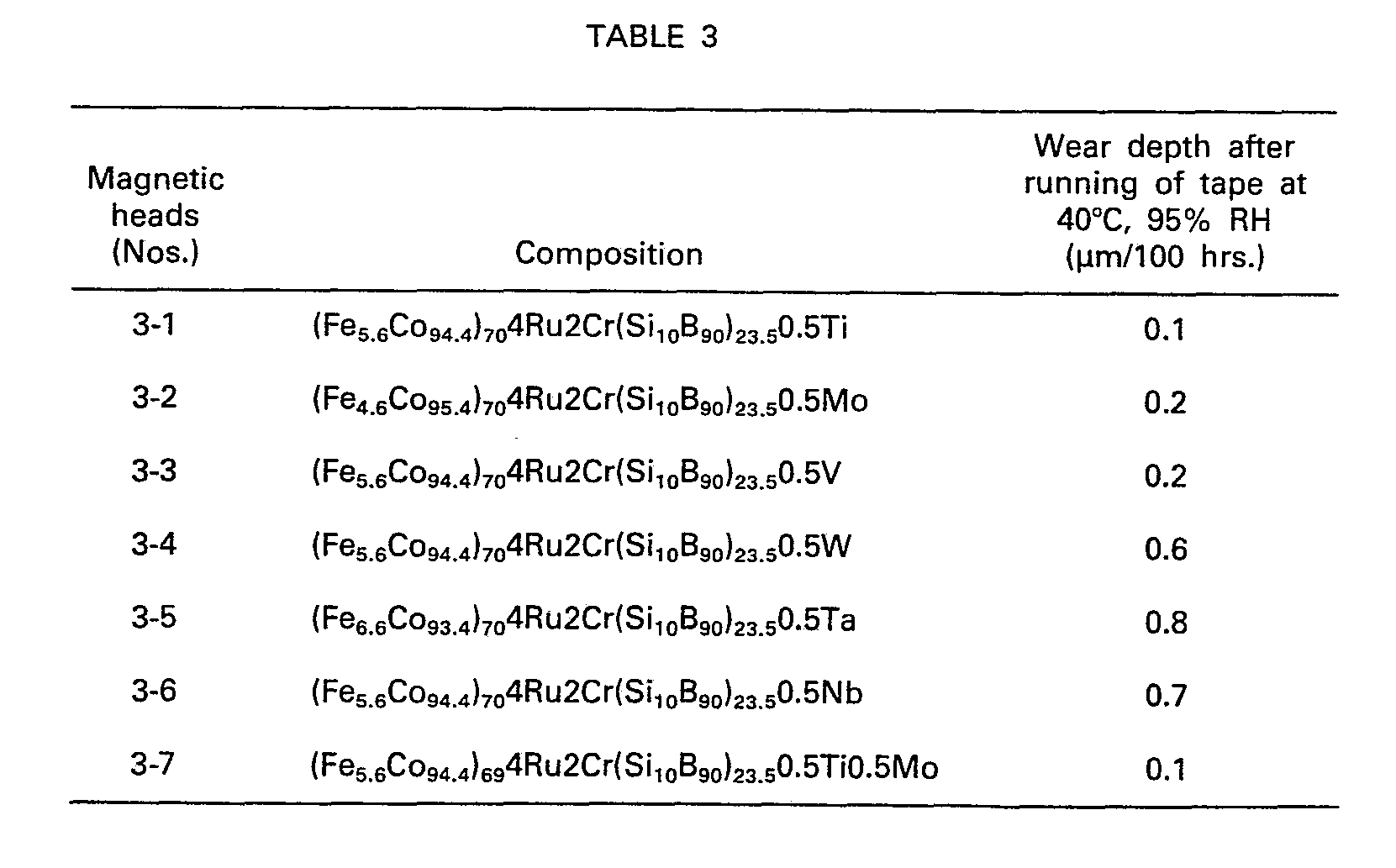
- the magnetic heads Nos. 2-1 through 2-10 and Nos 3-1 through 3-7 were manufactured by using the seventeen amorphous magnetic alloy materials given in Tables 2 and 3 and according to the procedure of Example 1.
- the running of the magnetic tape and measurement of the wear depth were carried out as in Example 1. However, the running of the magnetic tape was carried out only under the condition of 40°C and relative humidity of 95%.
- Tables 2 and 3 the wear depth reduced to that per 100 hours is given.
- the numerals directly before the platinum family, IV B -, V B - and VI B -family elements are the atomic percentage of the corresponding elements.
Landscapes
- Chemical & Material Sciences (AREA)
- Engineering & Computer Science (AREA)
- Organic Chemistry (AREA)
- Materials Engineering (AREA)
- Mechanical Engineering (AREA)
- Metallurgy (AREA)
- Manufacturing & Machinery (AREA)
- Physics & Mathematics (AREA)
- Electromagnetism (AREA)
- Dispersion Chemistry (AREA)
- Power Engineering (AREA)
- Magnetic Heads (AREA)
- Soft Magnetic Materials (AREA)
Description
- The present invention relates to an amorphous magnetic alloy material suited for use as a core material of a magnetic head having a high resistance against deterioration when stored for a long period of time at a high temperature and high humidity and having a high wear resistance, wherein said amorphous magnetic alloy material comprises iron and a high cobalt content and one or more elements of the group Ni, Cr, Mn, V, Ti, Mo, W, Nb, Zr, Pd, Pb, Cu, Ag and Au and at least one vitrification element of the group Si, B, P, C, Ge, Su, Ga, In, Sb and Al.
- Amorphous magnetic alloy materials of the above kind on the basis of iron and cobalt with a high cobalt content are known from FR-A-23 51 479. Further constituents of this alloy are at least one vitrification element and one or more elements of the group Ni, Cr, and other transition elements. These materials are used as core materials for transformers for which a high remanence and a low coercivity is required. Apart from that these materials have a low magnetostriction.
- This amorphous magnetic alloy material has attracted attention also as the core material of a magnetic head, because it exhibits excellent soft magnetic properties, high electric resistance and good workability. Research for practical application of the amorphous magnetic alloy material as the core material of a magnetic head is being actively conducted. In this research, it is deemed that the passivation film formed on the amorphous material, which is free from the crystal defects and which has a solid solution structure of a chemically uniform phase, is satisfactorily resistant against corrosion. Contrary to this, inconveniences may be brought about, when the magnetic head is manufactured by using conventional amorphous magnetic alloy materials. This is because the use of the amorphous magnetic alloy material as the component material of a magnetic head involves special problems explained hereinafter.
- Chemical wear, which occurs particularly in a contact type magnetic head, is a typical example of the inconveniences mentioned above. When the magnetic head is subjected to a slide contact with a magnetic tape over a long period of time, a film of oxide and the like is formed on the surface of an amorphous magnetic alloy material due to chemically corrosive media frequently contained in the magnetic coating layer of the magnetic tape or due to carbon dioxide, water and the like contained in the air. This film of oxide and the like is peeled off from the surface of an amorphous magnetic alloy material, when such film is subjected to stress generated because of the sliding of the tape or to the grinding effect of the magnetic powder. When chemical wear is the predominant reason which causes the wearing of an amorphous magnetic alloy material, the worn surface exhibits a mirror state. In addition, the sliding contact surface of a magnetic head is eccentrically worn out, with the consequence that the output and input levels of the magnetic head at a high frequency are decreased. From the standpoint of mechanical wear, in which the sliding contact surface of the magnetic head is mechanically ground, after having sliding contact with a tape for a long time, chemical wear is distinguished by the fact that amorphous magnetic alloy materials having equivalent hardness values to one another may be worn out in amounts different from one another depending upon the composition thereof. Mechanical wear is caused by the grinding particles which are generated from both magnetic head and tape by the sliding contact of the magnetic head with a tape and which grinds the sliding contact surface of the magnetic head. When the mechanical wear is the predominant reason which causes the wear of an amorphous magnetic alloy material, a number of scratches are formed on the worn surface by the generated grinding particles. When the mechanical wear is the predominant reason which causes the wear of magnetic head, the number of the scratches usually correspond to that of the generated grinding particles. Mechanical wear can be remarkably decreased by using a hard material as the component of a magnetic head.
- It is known in the field of magnetic recording that an amorphous magnetic alloy material containing at least iron and cobalt of the iron family element, the amount of which iron is from approximately 4 to 7 atomic % based on the iron family element, can satisfy the magnetic properties, particularly the magnetostriction required for the magnetic head. However, the known amorphous magnetic alloy material having the specified amount of iron also suffers from the drawbacks of high chemical wear and mechanical wear.
- The present applicant has proposed in JP-A-75542/1981 including predetermined quantity of a platinum family element into an amorphous magnetic alloy material, so as to decrease the chemical wear of the amorphous magnetic alloy material. The thus proposed amorphous magnetic alloy material exhibits a considerably great effect in decreasing the chemical wear under a normal operating condition of the magnetic head. However, in a case where magnetic heads are stored at a considerably high temperature and humidity condition over a long period of time, a film is formed on the surface of the amorphous magnetic alloy material and is discolored under the influence of moisture. As a result, the signal loss at the spacing between the magnetic head and tape is increased. In addition, the input and output levels at a high frequency decrease when the magnetic heads with the film are subsequently used for recording or regenerating. When the magnetic heads with the film are subsequently brought into a sliding contact with the tape, a part of the film, particularly in the neighbourhood of the head gap, is peeled off, with the consequence that the effective gap is increased or a loading is caused to occur in the gap. Furthermore, in a case where the recording and regenerating are conducted under a severe condition of considerably high temperature and humidity, chemical wear is conspicuously increased when the magnetic heads are slid against the tape.
- It is known from Zairyo Kagaku (Material Science) 15(4), 1978, p207 that, in order to enhance the corrosion resistance of an amorphous magnetic alloy material, chromium is incorporated into this material. It is also known from a report from MR7914 (1979) by the Institute of Electronics and Communication Engineers of Japan, Researching Association of Magnetic Recording, to include chromium into an amorphous magnetic alloy material for the magnetic head. When such a material is used as a component material of a magnetic head, the fact that the magnetic head is stored or retained in a severe condition for a long period of time does not seriously cause the inconveniences to appear at the recording and regenerating. However, according to research by the present inventors, it has been clarified that the chemical wear of the amorphous magnetic alloy material with chromium used as a component material of the magnetic head, is considerably large under a high temperature-and humidity condition and even under normal temperature and humidity conditions.
- It is a principal object of the present invention to discover a novel composition of an amorphous magnetic alloy material particularly suited for the component of a magnetic head to provide a magnetic head with a long life and small deterioration of the properties. When the novel alloy composition is used as the component of a magnetic head, it should exhibit a small chemical wear even under a severe condition of sliding contact with the tape. In addition, the novel alloy composition should not deteriorate, even when magnetic heads are stored under severe conditions.
- The amorphous magnetic alloy material of the present invention is expressed by the formula of

- p=4-7,
- q=83-96,
- r=010.
- The iron family elements are iron and cobalt, or iron, cobalt and nickel. The quantity of iron in terms of atomic weight percent based on the iron family element, should be from 4 to 7%, so that the magnetostriction can be kept as low as possible.
- At least one platinum family element M(1) is at least one element selected from the group consisting of ruthenium (Ru), palladium (Pd), platinum (Pt), iridium (lr) and rhodium (Rh) and more preferably includes ruthenium as the essential element or ruthenium alone.
- The transition metal element M(2) is at least one element of the first, second and third transition series in a broad sense, namely from Sc to Zn, from Y to Cd and from La to Hg of the long period table, respectively, except for the iron- and platinum-family elements and chromium.
- The vitrification element X, which is necessarily contained in the amorphous alloy and which may also be referred to as the metalloid element, is contained in the amorphous alloy material of the present invention in an amount of from about 20 to 26 atomic %, from the view point of satisfactory magnetic properties and amorphous degree.
- The vitrification element X is at least one of silicon (Si), boron (B), phosphorus (P), carbon (C), germanium (Ge), tin (Sn), gallium (Ga), indium (In), antimony (Sb), aluminium (Al) and the like. The vitrification element X may therefore occasionally be expressed by the formula of SikB,X(1)m which is a preferable vitrification element. In the formula of SikB,X(1 )m is k=5 to 20 atomic %, 1=60 to 95 atomic %, and m=0 to 20 %, and also X(1) is at least one element selected from the group consisting of phosphorus (P), germanium (Ge), tin (Sn) and carbon (C).
- The composition to the present invention is further explained with regard to the desirable properties of the material.
- The atomic percentages of the iron family element and the iron itself provide the amorphous magnetic alloy material with a satisfactorily low magnetostriction. The iron family element may contain nickel, as described above. However, since the saturation magnetic flux density decrease with the increase in the nickel content, the parameter "r", which represents the nickel atomic percentage in the iron family element, should be not more than 10%.
- The atomic percentage of the vitrification element ranges from 20 to 26 atomic %. When the vitrification element exceeds 26%, a satisfactory saturation magnetic flux density cannot be obtained. On the other hand, when the vitrification element is smaller than 20%, the crystallization temperature Tx is too low to use the amorphous magnetic alloy material for actual purposes. As stated hereinabove, a preferable vitrification element X is SikB,X(1 )m. When k is less than 5% and more than 20%, a satisfactory saturation magnetic flux density cannot be obtained. In addition, when m is more than 20%, it is difficult to vitrify the corresponding alloy material.
- When the atomic percentage of the vitrification element is from 20 to 26%, the crystallization temperature Tx is higher than the Curie temperature Tc, and thus an internal-stress relief heat treatment can easily be carried out.
- When the amount of M(1) is less than 0.01 atomic %, the effects of the present invention cannot be realized appreciably. On the other hand, when the amount of M(1) is more than 8%, it is difficult to vitrify the corresponding alloy material. The amount of M(1) is preferably from about 0.05 to 6 atomic %.
- The atomic % of the chromium ranges from 0.5 to 8 atomic %. When the amount of chromium is less than 0.5 atomic %, the effects of the present invention cannot be realized appreciably. On the other hand, when the amount of chromium exceeds about 8%, the Curie temperature Tc is decreased to less than approximately 100°C, with the consequence that satisfactory magnetic properties cannot be obtained. The amount of chromium is preferably from about 1 to 5%.
- The amorphous magnetic alloy material may additionally contain up to about 4 atomic % of at least one transition metal element M(2). When the amount exceeds 4 atomic %, the effects of the present invention are impaired.
- A further amorphous magnetic alloy material according to the present invention is expressed by the formula of

- p=4-7
- q=83-96
- r=010,
- The amorphous magnetic alloy materials described hereinabove according to the present invention are in an amorphous state having substantially no long range order. These materials may be in the form of a thin film, a fine wire and the like, but are usually in the form of a thin sheet having a thickness of from approximately 10 to 100 11m (microns).
- Processes for producing the amorphous magnetic alloy material of the present invention will now be described. An alloy in the gaseous or liquid state having a composition corresponding to that of the final product is super quenched from such state to a solid state. The super quenching method may be a sputtering, which allows a thin film to be formed on a substrate, but is usually a solidification method of an alloy melt, wherein the alloy melt is super quenched at a rate of 104°C/sec or higher, usually from 104 to 106°C/sec, thereby solidifying the alloy melt and producing a thin sheet of an amorphous alloy. In order to super quench the alloy in a molten state, the alloy melt may be sprayed from a nozzle and then rapidly cooled by one of various known rapid-cooling methods, such as a twin roll method, a single roll method or a centrifugal rapid-cooling method.
- A usual process for manufacturing a magnetic head using sheets of an amorphous magnetic alloy material according to the present invention will now be described. First, the sheets are subjected to a heat treatment which may be: an annealing intended to relieve the internal stress of the sheets and carried out under no magnetic field at a temperature lower than the crystallization temperature and higher than the Curie temperature, or; an annealing under a magnetic field and intended to relieve the internal stress and improve the magnetic properties of the sheets. Such a heat treatment is not indispensable, but is preferable. The annealing under a magnetic field may be the one using a stationary or a revolving magnetic field. The kind and condition of the annealing heat treatments may be optionally selected, taking into consideration of the composition and desired magnetic properties of an amorphous magnetic alloy material.
- After the heat treatment, a number of the sheets made of an amorphous magnetic alloy material are laminated by means of an insulating binder, so as to obtain a laminate block with a predetermined thickness which is then subjected to a grinding thereby manufacturing halves of the core of a magnetic head. Alternately, an individual sheet may be shaped into the predetermined form by blanking, photoetching and the like, and, subsequently, a plurality of these sheets are laminated by means of an insulating binder in such a manner to obtain the halves of core body of a magnetic head with a predetermined tracking width.
- Subsequently, a coil is provided on each half of the core body and is then installed in a core holder. After polishing the end of the core halves to be confronted with one another, the core halves are assembled to manufacture a core body and an insert material is located in the gap. The core body is then mounted in a shield case and a magnetic head is then completed by a resin molding.
- The magnetic head manufactured as described above may be a contact type or a non-contact type, in which the magnetic head is instantaneously in contact with a recording medium. The magnetic head can be used very conveniently in any audio or video recorder, computer, card reader and the like.
- The amorphous magnetic alloy material of the present invention is highly corrosion resistant due to the combination of chromium and platinum family element(s), and, the inconveniences in a magnetic head, due to chemical wear, can be prevented even where the magnetic head is operated or stored in a considerably severe condition.
- The amorphous magnetic alloy material according to the present invention can be advantageously mounted in the magnetic head case made of a conventional material, which reason is explained hereinafter. In the magnetic head, the core body, which is enclosed in a case, is grounded through the conduction via the case. This is to prevent the noise which is caused by the static electricity generated by the contact of the magnetic head with the tape and charged in the magnetic head. The charges of static electricity are conducted from the magnetic head to the ground via the case. The electric potential of a conventional amorphous magnetic alloy material based on cobalt is expressed in terms of:

- On the other hand, the electric potential of Permalloy, which is a conventional case material, is expressed in terms of:

- Therefore, a local cell is established between the core body, which is less noble and thus anodically behaves, and the case, which is noble and thus cathodically behaves. The core body is appreciably dissolved due to the anodic reaction, when the ambient media have high temperature and high humidity. The proposal of the present invention, namely the incorporation of at least one platinum element to the cobalt based amorphous magnetic alloy material, is to enhance the electric potential of such a material. The electric potential of ruthenium is expressed in terms of:

- The chromium, which is contained in the amorphous magnetic alloy material of the present invention, is an element which contributes to the formation of a passivation film and thus enhances the corrosion resistance. The reaction of chromium to form the passivation film seems to be as follows.

- Accordingly, the corrosion resistance of the amorphous magnetic alloy material under a high temperature and moisture condition is improved by both the passivation and noble states of the material.
- The present invention is hereinafter explained by way of the Examples.
- Table 1, below, indicates the prepared amorphous magnetic alloy materials having the formula of

- Subsequently, these master alloys were melted and then super quenched by a single roll method at a rate of approximately 106°C/sec, so that thirteen thin sheets in the form of a strip having a thickness of 30 pm were formed. These sheets were subjected to an X-ray diffraction and an electron diffraction. As a result, a diffraction pattern indicating a crystal structure was not detected at all.
- The sheets mentioned above were subjected to an annealing at a temperature higher than the Curie point and lower than the crystallization temperature in an argon atmosphere, while the annealing the thin sheets were not placed in the magnetic field.
- An epoxy adhesive was prepared using the main agent, which is a mixture of an epichlorohydrin- bisphenol A type epoxy resin having a molecular weight of about 3000 with an ethyl cellosolve, and a curing agent, which is a mixture of dicyandiamide with acetone. In the prepared epoxy adhesive, the weight proportion of the epoxy resin to dicyandiamide was 100:30.
- Subsequently, the epoxy adhesive was applied by a spray gun over one side of the eighteen thin sheets of every alloy material, laminated to each other, and tack bonded to each other with a jig. These pieces were preliminarily dried at 90°C for 20 minutes. These pieces were then pressed by a bonding jig at a pressure of 1 tlcm2 so as to remove excessive adhesive and, while being pressed, they were heated at 150°C for 5 hours, followed by unforced cooling. As a result, a 0.6 mm thick laminate block was obtained. The laminate block was ground, so that halves 1,1' of a core body, as shown in Fig. 1, were obtained.
- A fine wire was wound around each core half 1,1' at the section indicated by the
reference numeral 2,2' and the core halves 1,1' were accommodated in a core holder (not shown). The confronting surfaces of the core halves 1,1' defining theeffective gap 4 of a magnetic head were mirror finished by grinding and then polishing, while the core halves 1,1'were held in the core holders. The core halves 1,1'were butted with or confronted to one another with predetermined spaces inbetween according to a conventional method. - The above procedure was conducted using thirteen thin sheets, so that the thirteen magnetic heads Nos. 1-1 to 1-13 given in Table 1 were manufactured.
- With regard to the so-obtained thirteen magnetic heads, the chemical wear amount of the magnetic heads was measured under conditions frequently encountered in the operation of magnetic heads. The magnetic tape used in the measurement was of a γ-FezOs coating type and the binder of the coating layer comprised a vinyl chloride acetate thermoplastic resin. This magnetic tape was brought into contact with and displaced relative to the magnetic head, while the pressure of 20 g, which is a normal pressure in a casette tape, was applied to the magnetic tape. The displacement was carried out with the tape running at a speed of 4.75 cm/sec and under the environmental condition of 25°C and relative humidity of 50%. After running over a period of 1000 hours, the worn depth of the front surface of the magnetic heads was measured by means of a surface roughness tester. The measurement results of the thirteen magnetic heads were reduced to the wear depth per 100 hours of running and given in Table 1.
- The worn surface of the magnetic heads after running 100 hours was measured by means of an optic microscope. The worn surface of the magnetic heads Nos. 1-3 through 1-13 did not exhibit a mirror surface, and only scratches were observed. This fact indicates that the magnetic heads Nos. 1-3 through 1-13 were worn out only mechanically. Contrary to this, the magnetic heads Nos. 1-1 and 1-2 exhibited a mirror surface with metallic lustre, which indicates that chemical wear greater than mechanical wear took place during the running of the magnetic tape.
- In addition to the above measurement, thirteen magnetic heads were protractedly exposed under the condition of 70°C and relative humidity of 95% over the period of 200 hours, so as to test the storing property under inferior and severe condition. Subsequently, the magnetic heads were brought into contact with the running magnetic tape mentioned above and a regenerating sensitivity at 14 KHz was measured and then compared with the output level of the magnetic heads before the protracted exposure. The obtained changes in the output levels are given in Table 1.
- Furthermore, the magnetic tape was run with respect to the magnetic heads under a severe and inferior condition, so as to evaluate the chemical wear under such conditions. The running of the tape over the period of 1000 hours described hereinabove was carried out under a condition of 40°C and relative humidity of 95%, and the wear depth of the front surface of the magnetic heads was measured by means of a surface roughness tester. The measurement results of the thirteen magnetic heads are reduced to the wear depth per 100 hours and are given in Table 1. Similarly to the results under the frequently encountered condition, chemical wear and mechanical wear are the predominant reasons which caused the wear of the magnetic heads Nos. 1-1, 1-2 and Nos. 1-3 through 1-13.
- It will be understood from the results of Table 1 that, only by incorporating predetermined amounts of Cr and a platinum family element into an amorphous magnetic alloy material, can this material exhibit an excellent corrosion resistance under the severe and inferior conditions of running and storing.

- The magnetic heads Nos. 2-1 through 2-10 and Nos 3-1 through 3-7 were manufactured by using the seventeen amorphous magnetic alloy materials given in Tables 2 and 3 and according to the procedure of Example 1. The running of the magnetic tape and measurement of the wear depth were carried out as in Example 1. However, the running of the magnetic tape was carried out only under the condition of 40°C and relative humidity of 95%. In Tables 2 and 3 the wear depth reduced to that per 100 hours is given. Incidentally, the numerals directly before the platinum family, IVB-, VB- and VIB-family elements, are the atomic percentage of the corresponding elements.
- It will be understood from the results given in Tables 2 and 3 that all magnetic heads using the amorphous magnetic alloy compositions of the present invention are highly wear resistant under severe and inferior conditions.

- The magnetic properties of the Samples Nos. 1-1, 1-5 and 1-7 given in Table 1 were measured and the results were as follows.

and wherein M(1) is ruthenium alone or combined with at least one platinum family element selected from the group consisting of palladium, platinum, iridium, and rhodium, M(2) is at least one transition metal element other than iron, cobalt, nickel, ruthenium, palladium, platinum, iridium rhodium, and chromium, and X is at least one vitrification element.
wherein the total amount of M(2) and M(3) is 0,05―4 and wherein M(1) is ruthenium alone or combined with at least one platinum family element selected from the group consisting of palladium, platinum, iridium, and rhodium, M(2) is at least one transition metal element other than iron, cobalt, nickel, ruthenium, palladium, platinum, iridium, rhodium, and chromium, X is at least one vitrification element and M(3) is at least one of of the IVB family element, the VB family element and the VIB family element except for chromium. This material can be easily vitrified and easily formed as a sheet, and also provides the sheet with excellent surface roughness. Preferable (VB, VB and VIB (except for Cr) elements are, for example, Nb, Ta, Ti, Zr, V, W and Mo. Preferably, from one to five of these elements are contained in the amorphous magentic alloy material in an amount of from 0.05 to 4 atomic % and especially from about 0.08 to 3 atomic %. More preferably, the IVB, VB and VIB (except for Cr) elements are Ti, V and Mo, respectively, which are contained alone or in combination in the amorphous magnetic alloy material. These three elements can enhance the production yield of the amorphous material sheet with a small surface roughness, as compared with Nb, Ta, Zr and W. In addition, these three elements are effective for further decreasing the chemical wear under a severe sliding condition of the tape and also for mitigating the deterioration of a magnetic head in severe conditions. Furthermore, the crystallization temperature is enhanced by these three elements, and thus a stress-relief heat treatment can be easily carried out, which contributes to the production of a magnetic head.
Claims (7)

and wherein M(1) is ruthenium alone or combined with at least one platinum family element selected from the group consisting of palladium, platinum, iridium, and rhodium, M(2) is at least one transition metal element other than iron, cobalt, nickel, ruthenium, palladium, platinum, iridium rhodium, and chromium, and X is at least one vitrification element.

wherein the total amount of M(2) and M(3) is 0,05-4 and wherein M(1) is ruthenium alone or combined with at least one platinum family element selected from the group consisting of palladium, platinum, iridium, and rhodium, M(2) is at least one transition metal element other than iron, cobalt, nickel, ruthenium, palladium, platinum, iridium rhodium, and chromium, X is at least one vitrification element and M(3) is at least one of the IVB family element, the VB family element and the VIB family element except for chromium.
Applications Claiming Priority (2)
| Application Number | Priority Date | Filing Date | Title |
|---|---|---|---|
| JP127568/80 | 1980-09-15 | ||
| JP55127568A JPS5754251A (en) | 1980-09-15 | 1980-09-15 | Amorphous magnetic alloy material |
Publications (3)
| Publication Number | Publication Date |
|---|---|
| EP0048888A2 EP0048888A2 (en) | 1982-04-07 |
| EP0048888A3 EP0048888A3 (en) | 1983-09-07 |
| EP0048888B1 true EP0048888B1 (en) | 1985-12-11 |
Family
ID=14963256
Family Applications (1)
| Application Number | Title | Priority Date | Filing Date |
|---|---|---|---|
| EP81107273A Expired EP0048888B1 (en) | 1980-09-15 | 1981-09-15 | Amorphous magnetic alloy material |
Country Status (4)
| Country | Link |
|---|---|
| US (1) | US4416709A (en) |
| EP (1) | EP0048888B1 (en) |
| JP (1) | JPS5754251A (en) |
| DE (1) | DE3173204D1 (en) |
Families Citing this family (24)
| Publication number | Priority date | Publication date | Assignee | Title |
|---|---|---|---|---|
| JPS606907Y2 (en) * | 1980-12-05 | 1985-03-07 | ソニー株式会社 | sliding member |
| JPS57155339A (en) * | 1981-03-20 | 1982-09-25 | Matsushita Electric Ind Co Ltd | Magnetic head and production thereof |
| JPS587805A (en) * | 1981-07-08 | 1983-01-17 | Toshiba Corp | Amorphous alloy for magnetic head |
| US4578728A (en) * | 1981-12-09 | 1986-03-25 | Matsushita Electric Industrial Co., Ltd. | Magnetic head |
| JPS58120759A (en) * | 1982-01-08 | 1983-07-18 | Toshiba Corp | Amorphous alloy for magnetic head |
| US4616204A (en) * | 1982-08-09 | 1986-10-07 | Allied Corporation | Cut magnetic core formed of a glassy metal alloy |
| CA1205725A (en) * | 1982-09-06 | 1986-06-10 | Emiko Higashinakagawa | Corrosion-resistant and wear-resistant amorphous alloy and a method for preparing the same |
| US4697217A (en) * | 1982-10-13 | 1987-09-29 | Sanyo Electric Co., Ltd. | Magnetic head having a main core of sheet amorphous magnetic material |
| JPS5970585A (en) * | 1982-10-15 | 1984-04-21 | Hitachi Ltd | print head |
| EP0134792A1 (en) * | 1983-01-24 | 1985-03-27 | Western Electric Company, Incorporated | Magneto-electric pulse generating device |
| JPS6044383B2 (en) * | 1983-07-26 | 1985-10-03 | 株式会社東芝 | Amorphous alloy for magnetic heads |
| JPS59179748A (en) * | 1983-03-31 | 1984-10-12 | Toshiba Corp | Amorphous alloy for magnetic head |
| JPS60246604A (en) * | 1984-05-22 | 1985-12-06 | Hitachi Metals Ltd | Wound magnetic core |
| JPS6195503A (en) * | 1984-10-16 | 1986-05-14 | Sony Corp | Amorphous soft magnetic thin film |
| KR900007666B1 (en) * | 1984-11-12 | 1990-10-18 | 알프스 덴기 가부시기가이샤 | Amorphous Alloy for Magnetic Heads |
| JPH0777008B2 (en) * | 1985-06-21 | 1995-08-16 | 株式会社日立製作所 | Magnetic head using amorphous alloy film |
| JPS6169939A (en) * | 1985-09-19 | 1986-04-10 | Toshiba Corp | Amorphous alloy for magnetic head |
| JPS62270741A (en) * | 1986-05-19 | 1987-11-25 | Alps Electric Co Ltd | Amorphous alloy for magnetic head |
| DE3717043A1 (en) * | 1987-05-21 | 1988-12-15 | Vacuumschmelze Gmbh | AMORPHOUS ALLOY FOR STRIP-SHAPED SENSOR ELEMENTS |
| GB2284701B (en) * | 1993-11-26 | 1997-11-26 | Data Recording Heads Limited | Magnetic transducing head and method of manufacture thereof |
| EP0803882A1 (en) * | 1996-04-22 | 1997-10-29 | Read-Rite Corporation | Corrosion resistant amorphous magnetic alloys |
| AU8379398A (en) * | 1997-06-30 | 1999-01-19 | Wisconsin Alumni Research Foundation | Nanocrystal dispersed amorphous alloys and method of preparation thereof |
| US6512382B1 (en) | 2001-07-17 | 2003-01-28 | International Business Machines Corporation | Method for corrosion susceptibility testing of magnetic heads using simulated disk corrosion products |
| US7368022B2 (en) * | 2002-07-22 | 2008-05-06 | California Institute Of Technology | Bulk amorphous refractory glasses based on the Ni-Nb-Sn ternary alloy system |
Family Cites Families (13)
| Publication number | Priority date | Publication date | Assignee | Title |
|---|---|---|---|---|
| US3856513A (en) * | 1972-12-26 | 1974-12-24 | Allied Chem | Novel amorphous metals and amorphous metal articles |
| NL182182C (en) * | 1974-11-29 | 1988-01-18 | Allied Chem | DEVICE WITH AMORPHIC METAL ALLOY. |
| JPS5194211A (en) * | 1975-02-15 | 1976-08-18 | ||
| US4067732A (en) * | 1975-06-26 | 1978-01-10 | Allied Chemical Corporation | Amorphous alloys which include iron group elements and boron |
| US4052201A (en) * | 1975-06-26 | 1977-10-04 | Allied Chemical Corporation | Amorphous alloys with improved resistance to embrittlement upon heat treatment |
| US4056411A (en) * | 1976-05-14 | 1977-11-01 | Ho Sou Chen | Method of making magnetic devices including amorphous alloys |
| US4188211A (en) * | 1977-02-18 | 1980-02-12 | Tdk Electronics Company, Limited | Thermally stable amorphous magnetic alloy |
| JPS5949299B2 (en) * | 1977-09-12 | 1984-12-01 | ソニー株式会社 | amorphous magnetic alloy |
| US4225339A (en) * | 1977-12-28 | 1980-09-30 | Tokyo Shibaura Denki Kabushiki Kaisha | Amorphous alloy of high magnetic permeability |
| US4187128A (en) * | 1978-09-26 | 1980-02-05 | Bell Telephone Laboratories, Incorporated | Magnetic devices including amorphous alloys |
| DE2924280A1 (en) | 1979-06-15 | 1981-01-08 | Vacuumschmelze Gmbh | AMORPHE SOFT MAGNETIC ALLOY |
| WO1981000861A1 (en) * | 1979-09-21 | 1981-04-02 | Hitachi Metals Ltd | Amorphous alloys |
| JPS57160513A (en) * | 1981-03-31 | 1982-10-02 | Takeshi Masumoto | Maunfacture of amorphous metallic fine wire |
-
1980
- 1980-09-15 JP JP55127568A patent/JPS5754251A/en active Pending
-
1981
- 1981-09-10 US US06/300,921 patent/US4416709A/en not_active Expired - Lifetime
- 1981-09-15 EP EP81107273A patent/EP0048888B1/en not_active Expired
- 1981-09-15 DE DE8181107273T patent/DE3173204D1/en not_active Expired
Also Published As
| Publication number | Publication date |
|---|---|
| EP0048888A2 (en) | 1982-04-07 |
| EP0048888A3 (en) | 1983-09-07 |
| US4416709A (en) | 1983-11-22 |
| DE3173204D1 (en) | 1986-01-23 |
| JPS5754251A (en) | 1982-03-31 |
Similar Documents
| Publication | Publication Date | Title |
|---|---|---|
| US4416709A (en) | Amorphous magnetic alloy material | |
| US4079430A (en) | Magnetic head | |
| EP0234879B2 (en) | Ferromagnetic thin film and magnetic head using it | |
| JPH0230375B2 (en) | ||
| KR900007666B1 (en) | Amorphous Alloy for Magnetic Heads | |
| EP0510202B1 (en) | Amorphous soft magnetic material | |
| JPS6227146B2 (en) | ||
| JPS5935980B2 (en) | High magnetic permeability amorphous alloy for magnetic head core | |
| JPS6331535B2 (en) | ||
| JP2812572B2 (en) | Magnetic head | |
| JP2549145B2 (en) | Magnetic head | |
| JPS625980B2 (en) | ||
| EP0121046B1 (en) | Amorphous alloy for magnetic head and magnetic head with an amorphous alloy | |
| JPS5867846A (en) | High permeability alloy thin strip | |
| JPS5867848A (en) | High permeability alloy thin strip | |
| US4563225A (en) | Amorphous alloy for magnetic head and magnetic head with an amorphous alloy | |
| JPH0128491B2 (en) | ||
| JPS6116002A (en) | Magnetic head | |
| JP3221035B2 (en) | Magnetic head | |
| JP2020135907A (en) | Sputtering target for forming soft magnetic layer of perpendicular magnetic recording medium, perpendicular magnetic recording medium and its soft magnetic layer | |
| JPH05267031A (en) | Magnetic core material | |
| JPS5867845A (en) | High permeability alloy thin strip | |
| JPS6252907A (en) | Magnetically soft thin film | |
| JPH0463147B2 (en) | ||
| JPH0828298B2 (en) | Soft magnetic thin film |
Legal Events
| Date | Code | Title | Description |
|---|---|---|---|
| PUAI | Public reference made under article 153(3) epc to a published international application that has entered the european phase |
Free format text: ORIGINAL CODE: 0009012 |
|
| 17P | Request for examination filed |
Effective date: 19810915 |
|
| AK | Designated contracting states |
Designated state(s): DE FR GB NL |
|
| PUAL | Search report despatched |
Free format text: ORIGINAL CODE: 0009013 |
|
| AK | Designated contracting states |
Designated state(s): DE FR GB NL |
|
| RAP1 | Party data changed (applicant data changed or rights of an application transferred) |
Owner name: TDK CORPORATION |
|
| GRAA | (expected) grant |
Free format text: ORIGINAL CODE: 0009210 |
|
| AK | Designated contracting states |
Designated state(s): DE FR GB NL |
|
| REF | Corresponds to: |
Ref document number: 3173204 Country of ref document: DE Date of ref document: 19860123 |
|
| ET | Fr: translation filed | ||
| PLBI | Opposition filed |
Free format text: ORIGINAL CODE: 0009260 |
|
| 26 | Opposition filed |
Opponent name: COMMISSION DES COMMUNAUTES EUROPEENNES Effective date: 19860904 |
|
| NLR1 | Nl: opposition has been filed with the epo |
Opponent name: COMMISSION DES COMMUNAUTES EUROPEENNES |
|
| PLBN | Opposition rejected |
Free format text: ORIGINAL CODE: 0009273 |
|
| STAA | Information on the status of an ep patent application or granted ep patent |
Free format text: STATUS: OPPOSITION REJECTED |
|
| 27O | Opposition rejected |
Effective date: 19900101 |
|
| NLR2 | Nl: decision of opposition | ||
| PGFP | Annual fee paid to national office [announced via postgrant information from national office to epo] |
Ref country code: GB Payment date: 19920817 Year of fee payment: 12 |
|
| PGFP | Annual fee paid to national office [announced via postgrant information from national office to epo] |
Ref country code: FR Payment date: 19920901 Year of fee payment: 12 |
|
| PGFP | Annual fee paid to national office [announced via postgrant information from national office to epo] |
Ref country code: NL Payment date: 19920930 Year of fee payment: 12 |
|
| PGFP | Annual fee paid to national office [announced via postgrant information from national office to epo] |
Ref country code: DE Payment date: 19921103 Year of fee payment: 12 |
|
| PG25 | Lapsed in a contracting state [announced via postgrant information from national office to epo] |
Ref country code: GB Effective date: 19930915 |
|
| PG25 | Lapsed in a contracting state [announced via postgrant information from national office to epo] |
Ref country code: NL Effective date: 19940401 |
|
| GBPC | Gb: european patent ceased through non-payment of renewal fee |
Effective date: 19930915 |
|
| NLV4 | Nl: lapsed or anulled due to non-payment of the annual fee | ||
| PG25 | Lapsed in a contracting state [announced via postgrant information from national office to epo] |
Ref country code: FR Free format text: LAPSE BECAUSE OF NON-PAYMENT OF DUE FEES Effective date: 19940531 |
|
| PG25 | Lapsed in a contracting state [announced via postgrant information from national office to epo] |
Ref country code: DE Effective date: 19940601 |
|
| REG | Reference to a national code |
Ref country code: FR Ref legal event code: ST |