EP0048704B1 - Method of and apparatus for processing data generated by a synthetic aperture radar system - Google Patents
Method of and apparatus for processing data generated by a synthetic aperture radar system Download PDFInfo
- Publication number
- EP0048704B1 EP0048704B1 EP19810870035 EP81870035A EP0048704B1 EP 0048704 B1 EP0048704 B1 EP 0048704B1 EP 19810870035 EP19810870035 EP 19810870035 EP 81870035 A EP81870035 A EP 81870035A EP 0048704 B1 EP0048704 B1 EP 0048704B1
- Authority
- EP
- European Patent Office
- Prior art keywords
- processing
- signal
- cross
- signals
- azimuth
- Prior art date
- Legal status (The legal status is an assumption and is not a legal conclusion. Google has not performed a legal analysis and makes no representation as to the accuracy of the status listed.)
- Expired
Links
- 238000012545 processing Methods 0.000 title claims description 56
- 238000000034 method Methods 0.000 title claims description 19
- 238000013459 approach Methods 0.000 claims description 14
- 238000010183 spectrum analysis Methods 0.000 claims description 5
- 230000002596 correlated effect Effects 0.000 claims description 3
- 230000003139 buffering effect Effects 0.000 claims 3
- 238000009825 accumulation Methods 0.000 claims 2
- 238000004458 analytical method Methods 0.000 claims 1
- 230000006870 function Effects 0.000 description 16
- 238000010586 diagram Methods 0.000 description 12
- 238000012937 correction Methods 0.000 description 8
- 230000006835 compression Effects 0.000 description 6
- 238000007906 compression Methods 0.000 description 6
- 230000015654 memory Effects 0.000 description 6
- 230000005012 migration Effects 0.000 description 5
- 238000013508 migration Methods 0.000 description 5
- 238000001228 spectrum Methods 0.000 description 5
- 230000001427 coherent effect Effects 0.000 description 4
- 230000000875 corresponding effect Effects 0.000 description 4
- 230000010354 integration Effects 0.000 description 4
- 230000004044 response Effects 0.000 description 4
- 238000001914 filtration Methods 0.000 description 3
- PCTMTFRHKVHKIS-BMFZQQSSSA-N (1s,3r,4e,6e,8e,10e,12e,14e,16e,18s,19r,20r,21s,25r,27r,30r,31r,33s,35r,37s,38r)-3-[(2r,3s,4s,5s,6r)-4-amino-3,5-dihydroxy-6-methyloxan-2-yl]oxy-19,25,27,30,31,33,35,37-octahydroxy-18,20,21-trimethyl-23-oxo-22,39-dioxabicyclo[33.3.1]nonatriaconta-4,6,8,10 Chemical compound C1C=C2C[C@@H](OS(O)(=O)=O)CC[C@]2(C)[C@@H]2[C@@H]1[C@@H]1CC[C@H]([C@H](C)CCCC(C)C)[C@@]1(C)CC2.O[C@H]1[C@@H](N)[C@H](O)[C@@H](C)O[C@H]1O[C@H]1/C=C/C=C/C=C/C=C/C=C/C=C/C=C/[C@H](C)[C@@H](O)[C@@H](C)[C@H](C)OC(=O)C[C@H](O)C[C@H](O)CC[C@@H](O)[C@H](O)C[C@H](O)C[C@](O)(C[C@H](O)[C@H]2C(O)=O)O[C@H]2C1 PCTMTFRHKVHKIS-BMFZQQSSSA-N 0.000 description 2
- 238000003491 array Methods 0.000 description 2
- 238000002592 echocardiography Methods 0.000 description 2
- 239000011159 matrix material Substances 0.000 description 2
- 238000011045 prefiltration Methods 0.000 description 2
- 230000008569 process Effects 0.000 description 2
- 238000005070 sampling Methods 0.000 description 2
- 230000003595 spectral effect Effects 0.000 description 2
- 239000013598 vector Substances 0.000 description 2
- 230000000694 effects Effects 0.000 description 1
- 238000005286 illumination Methods 0.000 description 1
- 230000008520 organization Effects 0.000 description 1
- 238000012805 post-processing Methods 0.000 description 1
- 238000000926 separation method Methods 0.000 description 1
Images



Classifications
-
- G—PHYSICS
- G01—MEASURING; TESTING
- G01S—RADIO DIRECTION-FINDING; RADIO NAVIGATION; DETERMINING DISTANCE OR VELOCITY BY USE OF RADIO WAVES; LOCATING OR PRESENCE-DETECTING BY USE OF THE REFLECTION OR RERADIATION OF RADIO WAVES; ANALOGOUS ARRANGEMENTS USING OTHER WAVES
- G01S13/00—Systems using the reflection or reradiation of radio waves, e.g. radar systems; Analogous systems using reflection or reradiation of waves whose nature or wavelength is irrelevant or unspecified
- G01S13/88—Radar or analogous systems specially adapted for specific applications
- G01S13/89—Radar or analogous systems specially adapted for specific applications for mapping or imaging
- G01S13/90—Radar or analogous systems specially adapted for specific applications for mapping or imaging using synthetic aperture techniques, e.g. synthetic aperture radar [SAR] techniques
- G01S13/9004—SAR image acquisition techniques
- G01S13/9011—SAR image acquisition techniques with frequency domain processing of the SAR signals in azimuth
Definitions
- the present invention relates to a method of processing data generated by space or airborne Synthetic Aperture Radar (SAR) systems and to an apparatus for carrying out said method.
- SAR Synthetic Aperture Radar
- a radar is installed aboard a spacecraft or aircraft; by processing the return signals or echoes of the emitted signals, it is possible to generate an image of the ground.
- a point target will be illuminated as long as it lies in the antenna ground patch and consequently the echoes will contain information relating to that point target as long as it is illuminated: For example, this corresponds to the time interval T 6- T 1 on Fig. 1 or the distance A 1 -As covered by the satellite along its path. This distance is called the synthetic aperture length.
- the signals emitted by the radar are not continuous: at times T,, T 2 , T 3 ... T 6 snapshots are made. In order to obtain a good resolution all the radar return signals received at these times are processed.
- the processing principle consists of coherent integration of the radar echo sample vectors: prior to summation of all signal samples obtained from a specific point scatterer during its aperture time duration, the sample vectors are rotated by the appropriate phase angles (given by the known trajectory) so that all samples from that point are added in phase and those of other points are substantially suppressed due to incoherent addition.
- the result of the processing is that all point scatterers are resolved with respect to their position on the ground and an image is obtained.
- the operation of coherent integration can be performed mathematically as a correlation of the stored received signal samples with a reference function of which the phase variation corresponds to the one of a point scatterer.
- the synthetic aperture radar works with monochromatic illumination of a scene the image has a speckly, grainy appearance.
- a single look image defined as an image observed just sufficiently long enough to obtain the required resolution.
- a multi-look approach can be used.
- the multiple look processing principle consists in adding a number of single-look images in a non-coherent manner.
- a method for obtaining multiple looks is to collect the data for a certain length of time, process the information into one look, process the next set of data into the next look followed by incoherent addition of the different looks.
- the data from a first look is obtained by processing a first portion of the Doppler spectrum and storing the data, then the next portion of the Doppler spectrum is processed and the data therefrom is stored and added to the previous one and so on until the synthetic aperture is generated.
- a short duration pulse e.g. 70 n sec
- pulse- compression another method, known as pulse- compression. This method consists in transmitting the needed energy dispersed over a longer period of time and processing the obtained data using pulse compression.
- a linear FM signal or chirped signal is used because it is easy to compress.
- the data collected from a single point target is dispersed in range time (R) and in azimuth direction (AZ).
- the range time is equal to the chirp duration, e.g. ⁇ 30 psec.
- This data can be compressed either in range or in azimuth first.
- compression is meant that the data collapses to one line.
- range compression the data would collapse to one line along the azimuth direction and in the case of azimuth compression the data would collapse to one line in the range time direction.
- azimuth compression the data would collapse to one line in the range time direction.
- the range can first be compressed and afterwards the azimuth.
- the data point corresponding to a point target is the intersection of those two lines.
- the compression is performed by cross-correlation of the received signals with reference functions which depend on the radar sensor parameters, the satellite orbit, the spacecraft's attitude and earth parameters.
- the received signals are stored in matrix form:
- the reference function is of course also a matrix.
- the commonly used correlation processing is either a processing in time-frequency domain or a processing by spectral analysis.
- a multi-look imagery can be obtained by incoherent addition or consecutive correlation.
- the commonly used method to generate multi-look imagery is to perform the correlation only over a part of the total signal history making use of the property of the signal that consecutive parts of the signal history extended in time also occupy consecutive parts of the total Doppler spectrum. This method is called "look filtering" and is an effective means to reduce the amount of azimuth correlation processing but it creates an appreciable processing load by itself.
- range migration This variation is given approximately by: where AR and X are measured from the point at which the target is at beam centre position. The beam centre position is at X o distance from the point at closest target approach.
- the present invention relates in particular to azimuth processing.
- Prior art azimuth processing involves the correlation of radar returns at each resolvable range with a reference function, resulting in a set of compressed pulses which are stored in a memory.
- the further processing of these pulses involves range migration correction.
- This processing can be carried out either in the time domain, involving delay-time structures, or in the frequency domain requiring the use of a discrete Fourier transform, and buffer storage.
- Final processing includes Doppler history processing to derive the output pixels.
- the disadvantages of the prior art systems are that they require high processing rates due to their complicated structure, and large mass memories.
- the object of the invention is to extract single and multi-look imagery data from the data signals of a synthetic aperture radar (SAR) system in efficient manner by an improved method of processing the data signals.
- SAR synthetic aperture radar
- the received SAR data signals are cross-correlated with a reference function signal having a frequency-time history equal and opposite to the ideal received signal, thereby to produce a series of constant-frequency signals displaced in time, and further processing the constant-frequency signals thus produced by a discrete Fourier transform (DFT) spectral analysis.
- DFT discrete Fourier transform
- the processed signals then are selected and detected based on Doppler centroid estimation (known per se) before being accumulated and compensated for geometric distortions.
- the method according to the invention can be implemented as a one-dimensional approach accepting already compressed (either in range or in azimuth) data signals or as a two-dimensional approach which is able to use as input raw data signals extending both in azimuth and in range domain.
- the invention can be implemented in a one-dimensional or two-dimensional approach.
- Fig. 3 there is shown a schematic block diagram of a first embodiment for a one-dimensional approach.
- This embodiment uses a range compressed signal which is first of all applied to a well-known linear range migration correction unit LRMC for correction as explained hereinbefore.
- the corrected azimuth radar signal is then processed as follows.
- the first step consists in cross-correlating (block 1) the received signal with an azimuth reference function from generator 2.
- the reference function is chosen to have a frequency-time history equal and opposite to the frequency-time history of the ideal received signal.
- This signal is given by an exponential function, the instantaneous frequency of which can be calculated by differentiating the phase thereof and is given by where
- Fig. 4 shows a frequency-time history of such a signal for one point target. The beginning of the signal corresponds with the point target entering the antenna main lobe and the end of the signal indicates that the antenna main lobe no longer detects the point target.
- the reference function generator 2 can be implemented in various forms by those skilled in the art.
- the reference function used is a linear FM signal labeled RS on Fig. 6a.
- the multiplication of these two signals means that their arguments are added.
- the frequency of the product will thus be constant as shown by the line labeled CS in Fig. 6c.
- the cross-correlation with the reference function RS will also produce a constant-frequency signal but of a higher frequency as illustrated by line CS2 on Fig. 6e.
- the cross-correlation of a series of input signals corresponding to a series of point targets will produce a series of constant-frequency signals CS 1 , CS 2 , ... CS n as shown on Fig. 7.
- the spectral band occupied by these correlated signals is equal to the pulse repetition frequency (p.r.f.).
- Constant frequency lines are contained in a single range bin as they are generated by iso-range targets.
- the memory organization is such that the read-in mode is in range order (fast time) and the read-out is in azimuth order (slow rate).
- the next process step consists in an azimuth processing of the signal in blocks 5 and 6 (as illustrated in Fig. 3).
- the signal processing uses the well-known discrete Fourier transform DFT (block 5) associated with a weighting select and detect function (block 6) as will be explained hereinafter with reference to Fig. 8 which shows a family of target signals in the time-frequency diagram.
- DFT discrete Fourier transform
- block 6 weighting select and detect function
- Fig. 8 shows a family of target signals in the time-frequency diagram.
- a number of N points are processed in block 5 corresponding to a vertical rectangle abcd in the diagram.
- This rectangle can be divided into two parts: one part labelled 1 which lies entirely in the time-frequency region of actual targets and will consequently define unambiguous targets, and a second part labelled 2 which does not lie inside the time-frequency region of any actual target, i.e. a part which contains information relating to different targets.
- the next DFT operation is applied after a predetermined time and similarly
- the first part 1 of the first DFT operation and the second part 2' of the second DFT operation cover all range bins generated within one cycle period of the reference function.
- Functional block 6 operates to select the samples corresponding to the parts 1 and 2' in the time-frequency domain of Fig. 8. Although continuous frequency is provided in the output data (part 1 +part 2'), not all input data was needed to provide it. The fact that not all the information has been used leads to not achieving the inherent resolution of the data. Although yielding a poor resolution this approach is very attractive since the processing of the signals is very simple, and is suitable e.g. for quick look purposes. A high resolution can be obtained by using a larger part of the Doppler spectrum available at the expense of a lower DFT efficiency.
- the next DFT operation also defines a rectangle situated between the two vertical guard lines. This DFT overlaps a part of the preceding one.
- the starting frequency of this next DFT operation depends on the number n of equal parts used.
- a condition is that the first part of any DFT operation covers the same frequency band as the second part of the preceding DFT operation, e.g.: By using smaller size DFT frequency bands (or higher number n) it is possible to cover a greater portion of the total information area (area between the guard lines).
- the different parts of the DFT operation with the same frequency band can be considered as different looks.
- the information stored in area ABCD on Fig. 9 can be divided into D i+3 L 1 ; D I+2 L 2 ; D i+1 L 3 ; D i L 4 .
- Appropriate data selection in block 6 is based on Doppler centroid estimation DCE (known per se). Consecutive blocks of processed data are summed (incoherently) and stored (block 8) until all looks are accumulated. Prior to look summation, looks registration (block 7) might be required, depending on known azimuth correlation mismatch conditions. Output sample rate adjustment in order to obtain a constant rate over the full range swath is also required (block 9) in case the F. M. rate of the processor generated signal is varied as a function of range. Due to specific geometric distortions introduced by the processor a deskew processing operation (block 10) is necessary to compensate for it.
- DCE Doppler centroid estimation
- Fig. 10 illustrates a variation to the embodiment described heretofore.
- This second embodiment essentially differs from the preceding one (Fig. 3) by using bandpass filters 11 prior to performing the spectral analysis thereby to achieve a pre-filtering operation on the cross-correlated signal CS.
- This pre-filter operation essentially permits to perform the DFT operation with good efficiency in case the DFT block length covers a large part of the available Doppler bandwidth. This must be the case for efficient single look processing.
- the implementation of the pre-filter operation is of crucial importance in order to keep the number of operations involved to the minimum (e.g. by polyphase filtering). For a single look approach, the operation of the embodiment of Fig. 10 is explained as follows with reference to the time-frequency diagram of Fig. 11.
- the total information of an illuminated patch on ground is divided by the filters into a number M of different frequency regions labelled AF,, AF 2 and ⁇ F 3 on Fig. 11. If one takes in each of said regions the maximum possible size DFT sampling, e.g. DFT,, DFT, and DFT 3 , the total information used will increase as shown by the shaded and dotted rectangles. Comparing with the diagram of Fig. 8 it is seen that the dotted rectangles represent the information used with the first approach and that the shaded rectangles represent the increase of used information in the second approach. This result in an improved resolution as compared to the first described embodiment.
- each part of information in each of said frequency regions AFi is divided into equal parts with a certain overlap as illustrated in Fig. 12. These parts are labelled L 1 , L 2 , L 3 in the ⁇ F 1 region.
- the advantages of this multi-look processing as compared to the first approach are as follows:
- the processing approaches described heretofore perform a one-dimensional spectral analysis in that they use as input a signal which has previously been compressed.
- the input signal is a range compressed signal, that is a signal of which the range width is reduced essentially to one line containing the range information.
- the processing performed in the described system is an azimuth processing.
- a second embodiment of the invention method is directed to a two-dimensional processing such that the input needs not to be a compressed signal and consequently the LRMC device can be omitted thereby to avoid the complex operation of such a device.
- a target area extended in range and azimuth as depicted in Fig. 13.
- the loss in data usage for processing is small.
- This second embodiment is schematically illustrated in Fig. 14.
- the cross-correlation with a reference function signal or dechirp operation (block 12) is performed in range and azimuth whereby the points are resolved in frequency differences along the two dimensions azimuth and range.
- An array of MxL bandpass filters 13 is used after the cross-correlation operation allowing for efficient single-look processing and data array selection.
- the output from each of the MxL filters is applied to a separate processing channel which applies a two-dimensional discrete Fourier transform (DFT) operation (block 14).
- DFT discrete Fourier transform
- the other elements in each channel are similar to those in the embodiments described hereinbefore.
- the signals from the MxL channels may be added either coherently or incoherently depending on the spatial resolution and the number of looks desired.
- Look registration can be controlled exactly by applying the appropriate phase correction term prior to DFT operation (i.e. in combination with the weighting operation).
- the bandpass filter operation in a specific dimension may be omitted in case only multi-look processing is performed in that dimension and, in case of azimuth processing, look registration correction is either not required (e.g. all arrays contain the same range interval) or performed after the DFT operation.
Landscapes
- Engineering & Computer Science (AREA)
- Remote Sensing (AREA)
- Radar, Positioning & Navigation (AREA)
- Physics & Mathematics (AREA)
- Signal Processing (AREA)
- Electromagnetism (AREA)
- Computer Networks & Wireless Communication (AREA)
- General Physics & Mathematics (AREA)
- Radar Systems Or Details Thereof (AREA)
Description
- The present invention relates to a method of processing data generated by space or airborne Synthetic Aperture Radar (SAR) systems and to an apparatus for carrying out said method.
- In order that the invention may be readily understood, the basic principles of a SAR system will first briefly be described. In a SAR system a radar is installed aboard a spacecraft or aircraft; by processing the return signals or echoes of the emitted signals, it is possible to generate an image of the ground.
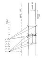
- Consider a satellite which is provided with a radar moving in the azimuth direction (Fig. 1). At time t=T" the position of the radar is A1 and at that moment the radar illuminates a patch on the ground indicated by ABCD. At that time the point target X enters the antenna main lobe and the echo received on the satellite contains information relating to that target. At time t=T6 the satellite reaches the position A6 and at that time the point target X leaves the antenna main lobe. At time t=T6+Δt, the echo received on the satellite will not contain anymore information relating to that point target. In other words, a point target will be illuminated as long as it lies in the antenna ground patch and consequently the echoes will contain information relating to that point target as long as it is illuminated: For example, this corresponds to the time interval T6-T1 on Fig. 1 or the distance A1-As covered by the satellite along its path. This distance is called the synthetic aperture length. The signals emitted by the radar are not continuous: at times T,, T2, T3 ... T6 snapshots are made. In order to obtain a good resolution all the radar return signals received at these times are processed.
- The processing principle consists of coherent integration of the radar echo sample vectors: prior to summation of all signal samples obtained from a specific point scatterer during its aperture time duration, the sample vectors are rotated by the appropriate phase angles (given by the known trajectory) so that all samples from that point are added in phase and those of other points are substantially suppressed due to incoherent addition. The result of the processing is that all point scatterers are resolved with respect to their position on the ground and an image is obtained. Although the principle of coherent integration of SAR data is simple, the implementation of this concept to yield useful imagery in a practical and cost effective manner is a non-trivial problem due to the very large number of operations involved. The operation of coherent integration can be performed mathematically as a correlation of the stored received signal samples with a reference function of which the phase variation corresponds to the one of a point scatterer.
- Since the synthetic aperture radar works with monochromatic illumination of a scene the image has a speckly, grainy appearance. A single look image defined as an image observed just sufficiently long enough to obtain the required resolution. In order to reduce the speckle phenomena a multi-look approach can be used. The multiple look processing principle consists in adding a number of single-look images in a non-coherent manner. A method for obtaining multiple looks is to collect the data for a certain length of time, process the information into one look, process the next set of data into the next look followed by incoherent addition of the different looks.
- Since in the azimuth direction the Doppler effect is present, it is possible to apply the multiple look principle in the azimuth direction by using the fact that each look will have another place in the Doppler spectrum. It is clear that the images are separated in a spectral sense which is equivalent to a spatial separation of the images.
- The data from a first look is obtained by processing a first portion of the Doppler spectrum and storing the data, then the next portion of the Doppler spectrum is processed and the data therefrom is stored and added to the previous one and so on until the synthetic aperture is generated.
- When the data is processed in "n" separate looks, the resolution element is "n" times larger and the picture is thus smoothed at the expense of the resolution.
- In order to get an adequate signal back from the target, i.e. to get the desired resolution a short duration pulse (e.g. 70 n sec) with a peak power of several hundreds of kilowatts is needed. This is very difficult to implement and therefore another method, known as pulse- compression, is used. This method consists in transmitting the needed energy dispersed over a longer period of time and processing the obtained data using pulse compression. In practice a linear FM signal or chirped signal is used because it is easy to compress.
- The data collected from a single point target is dispersed in range time (R) and in azimuth direction (AZ). The range time is equal to the chirp duration, e.g. ± 30 psec.
- This data can be compressed either in range or in azimuth first. By compression is meant that the data collapses to one line. In the case of range compression the data would collapse to one line along the azimuth direction and in the case of azimuth compression the data would collapse to one line in the range time direction. In order to obtain the point target data the range can first be compressed and afterwards the azimuth. The data point corresponding to a point target is the intersection of those two lines. In practice the compression is performed by cross-correlation of the received signals with reference functions which depend on the radar sensor parameters, the satellite orbit, the spacecraft's attitude and earth parameters.
- For the cross-correlation the received signals are stored in matrix form:

- n=number of snapshots made between A1 and A6
- p=number of samples in range direction.
- For example, for a typical spacecraft radar, a resolution of 25 meters and a range swath of about 100 km corresponds to n= 1000; p=6000. The reference function is of course also a matrix.
- The commonly used correlation processing is either a processing in time-frequency domain or a processing by spectral analysis.
- A multi-look imagery can be obtained by incoherent addition or consecutive correlation. The commonly used method to generate multi-look imagery is to perform the correlation only over a part of the total signal history making use of the property of the signal that consecutive parts of the signal history extended in time also occupy consecutive parts of the total Doppler spectrum. This method is called "look filtering" and is an effective means to reduce the amount of azimuth correlation processing but it creates an appreciable processing load by itself.
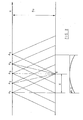
- The state-of-the-art methods are illustrated by the journal article "Synthetic Aperture Radar Real-time Processing" by D. J. Bonfield and J. R. E. Thomas (IEE Proceedings, Vol. 127, PT. F, No. 2, April 1980). These methods use an input signal an already compressed range signal. In that case, the compressed signal must be corrected by means of a linear range migration correction unit LRMC. The range migration of a point target is due to the fact that for a target the range changes with the position of the spacecraft travelling along the X-axis with an antenna illuminating a point target 0 on the ground (Fig. 2). This point is for the first time illuminated when the spacecraft reaches position A1 where the range (distance A,-0) is at a maximum. When the spacecraft reaches point A3 the range is at a minimum. The variation in range AR is called range migration This variation is given approximately by:

- In many cases (S-band or higher frequency radars) the correction for the linear term is sufficient and can be implemented prior to azimuth processing.
- The present invention relates in particular to azimuth processing. Prior art azimuth processing (see for instance the article mentioned above) involves the correlation of radar returns at each resolvable range with a reference function, resulting in a set of compressed pulses which are stored in a memory. The further processing of these pulses involves range migration correction. This processing can be carried out either in the time domain, involving delay-time structures, or in the frequency domain requiring the use of a discrete Fourier transform, and buffer storage. Final processing includes Doppler history processing to derive the output pixels. The disadvantages of the prior art systems are that they require high processing rates due to their complicated structure, and large mass memories.
- The object of the invention is to extract single and multi-look imagery data from the data signals of a synthetic aperture radar (SAR) system in efficient manner by an improved method of processing the data signals.
- In accordance with the invention, the received SAR data signals are cross-correlated with a reference function signal having a frequency-time history equal and opposite to the ideal received signal, thereby to produce a series of constant-frequency signals displaced in time, and further processing the constant-frequency signals thus produced by a discrete Fourier transform (DFT) spectral analysis. The processed signals then are selected and detected based on Doppler centroid estimation (known per se) before being accumulated and compensated for geometric distortions.
- The method according to the invention can be implemented as a one-dimensional approach accepting already compressed (either in range or in azimuth) data signals or as a two-dimensional approach which is able to use as input raw data signals extending both in azimuth and in range domain.
- The invention is further described hereinafter with reference to the accompanying drawings in which:
- Figs. 1 and 2 are diagrams serving to illustrate the operation of a SAR system;
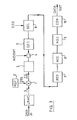
- Fig. 3 is a schematic block diagram depicting a first embodiment of the invention;
- Figs. 4 and 5 depict the frequency-time history of the compressed SAR signal;
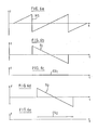
- Figs. 6 and 7 depict the first step of processing in accordance with the invention;
- Fig. 8 is a diagram in time-frequency domain depicting the second step of single-look processing in the embodiment of Fig. 3;
- Fig. 9 is a diagram in time-frequency domain depicting the second step of multi-look processing in the embodiment of Fig. 3;
- Fig. 10 is a schematic block diagram depicting a variation to the embodiment of Fig. 3;
- Fig. 11 is a diagram in time-frequency domain depicting the second step of single-look processing in the embodiment of Fig. 10;
- Fig. 12 depicts the second step of multi-look processing in the embodiment of Fig. 10;
- Fig. 13 depicts the response of a target area in range and azimuth;
- Fig. 14 is a schematic block diagram depicting a second embodiment of the invention.
- The invention can be implemented in a one-dimensional or two-dimensional approach. Referring first to Fig. 3 there is shown a schematic block diagram of a first embodiment for a one-dimensional approach. This embodiment uses a range compressed signal which is first of all applied to a well-known linear range migration correction unit LRMC for correction as explained hereinbefore. The corrected azimuth radar signal is then processed as follows.
- The first step consists in cross-correlating (block 1) the received signal with an azimuth reference function from
generator 2. The reference function is chosen to have a frequency-time history equal and opposite to the frequency-time history of the ideal received signal. This signal is given by an exponential function, the instantaneous frequency of which can be calculated by differentiating the phase thereof and is given by
- z=azimuth sampling period
- Ka=azimuth FM rate (in Hz/sec)
- n=sample number
- The relation shows that the frequency varies linearly with time. Fig. 4 shows a frequency-time history of such a signal for one point target. The beginning of the signal corresponds with the point target entering the antenna main lobe and the end of the signal indicates that the antenna main lobe no longer detects the point target.
- For a series of point targets with constant range there is produced a series of reflected signals having the same frequency history but which are displaced in time (azimuth direction) one relative to the other as shown in Fig. 5.
- The
reference function generator 2 can be implemented in various forms by those skilled in the art. The reference function used is a linear FM signal labeled RS on Fig. 6a. - Since now the input signal S, and the reference signal RS are exponential functions, the multiplication of these two signals means that their arguments are added. The frequency of the product will thus be constant as shown by the line labeled CS in Fig. 6c. For a second input signal S2 detected at a later time (Fig. 6d) the cross-correlation with the reference function RS will also produce a constant-frequency signal but of a higher frequency as illustrated by line CS2 on Fig. 6e. Thus, the cross-correlation of a series of input signals corresponding to a series of point targets will produce a series of constant-frequency signals CS1, CS2, ... CSn as shown on Fig. 7. The spectral band occupied by these correlated signals is equal to the pulse repetition frequency (p.r.f.). Constant frequency lines are contained in a single range bin as they are generated by iso-range targets.
- Since the information is received rangeline per rangeline and the information is needed in azimuth direction the information is stored in a
buffer memory 3. The memory organization is such that the read-in mode is in range order (fast time) and the read-out is in azimuth order (slow rate). - The next process step consists in an azimuth processing of the signal in
blocks 5 and 6 (as illustrated in Fig. 3). The signal processing uses the well-known discrete Fourier transform DFT (block 5) associated with a weighting select and detect function (block 6) as will be explained hereinafter with reference to Fig. 8 which shows a family of target signals in the time-frequency diagram. A number of N points are processed inblock 5 corresponding to a vertical rectangle abcd in the diagram. This rectangle can be divided into two parts: one part labelled 1 which lies entirely in the time-frequency region of actual targets and will consequently define unambiguous targets, and a second part labelled 2 which does not lie inside the time-frequency region of any actual target, i.e. a part which contains information relating to different targets. Thus the first part will only give good results and the second part must be discarded. The next DFT operation is applied after a predetermined time and similarly defines tworectangles 11 and 2': here part 2' contains information relating to actual target and part 1' does not. - The
first part 1 of the first DFT operation and the second part 2' of the second DFT operation cover all range bins generated within one cycle period of the reference function.Functional block 6 operates to select the samples corresponding to theparts 1 and 2' in the time-frequency domain of Fig. 8. Although continuous frequency is provided in the output data (part 1 +part 2'), not all input data was needed to provide it. The fact that not all the information has been used leads to not achieving the inherent resolution of the data. Although yielding a poor resolution this approach is very attractive since the processing of the signals is very simple, and is suitable e.g. for quick look purposes. A high resolution can be obtained by using a larger part of the Doppler spectrum available at the expense of a lower DFT efficiency. - Multi-look processing can be performed as illustrated on Fig. 9. Considering the
rectangle 1 of Fig. 8, it can be divided into n equal parts labelled DiLj, where i<jGn. In Fig. 9, n=4. - The next DFT operation also defines a rectangle situated between the two vertical guard lines. This DFT overlaps a part of the preceding one. The starting frequency of this next DFT operation depends on the number n of equal parts used. A condition is that the first part of any DFT operation covers the same frequency band as the second part of the preceding DFT operation, e.g.:

- Since one constant-frequency line represents one point target, the different parts of the DFT operation with the same frequency band can be considered as different looks. In other words the information stored in area ABCD on Fig. 9 can be divided into Di+3 L1; DI+2 L2; Di+1 L3; Di L4.
- Appropriate data selection in block 6 (Fig. 3) is based on Doppler centroid estimation DCE (known per se). Consecutive blocks of processed data are summed (incoherently) and stored (block 8) until all looks are accumulated. Prior to look summation, looks registration (block 7) might be required, depending on known azimuth correlation mismatch conditions. Output sample rate adjustment in order to obtain a constant rate over the full range swath is also required (block 9) in case the F. M. rate of the processor generated signal is varied as a function of range. Due to specific geometric distortions introduced by the processor a deskew processing operation (block 10) is necessary to compensate for it.
- Fig. 10 illustrates a variation to the embodiment described heretofore. This second embodiment essentially differs from the preceding one (Fig. 3) by using
bandpass filters 11 prior to performing the spectral analysis thereby to achieve a pre-filtering operation on the cross-correlated signal CS. This pre-filter operation essentially permits to perform the DFT operation with good efficiency in case the DFT block length covers a large part of the available Doppler bandwidth. This must be the case for efficient single look processing. The implementation of the pre-filter operation is of crucial importance in order to keep the number of operations involved to the minimum (e.g. by polyphase filtering). For a single look approach, the operation of the embodiment of Fig. 10 is explained as follows with reference to the time-frequency diagram of Fig. 11. The total information of an illuminated patch on ground is divided by the filters into a number M of different frequency regions labelled AF,, AF2 and ΔF3 on Fig. 11. If one takes in each of said regions the maximum possible size DFT sampling, e.g. DFT,, DFT, and DFT3, the total information used will increase as shown by the shaded and dotted rectangles. Comparing with the diagram of Fig. 8 it is seen that the dotted rectangles represent the information used with the first approach and that the shaded rectangles represent the increase of used information in the second approach. This result in an improved resolution as compared to the first described embodiment. - Also the second embodiment can be applied for multi-look processing. In that case, each part of information in each of said frequency regions AFi is divided into equal parts with a certain overlap as illustrated in Fig. 12. These parts are labelled L1, L2, L3 in the ΔF1 region. The advantages of this multi-look processing as compared to the first approach are as follows:
- - feasibility of efficient single-look processing;
- - multi-look imagery can be obtained by performing post processing integration of single look data in which case no look sum memory is required;
- - due to the small number of output signals per DFT block the data registration errors are small and correction for these may be omitted;
- - the buffer memory requirements are lower in principle.
- The processing approaches described heretofore perform a one-dimensional spectral analysis in that they use as input a signal which has previously been compressed. In the embodiments depicted in Figs. 3 and 10 the input signal is a range compressed signal, that is a signal of which the range width is reduced essentially to one line containing the range information. In those cases the processing performed in the described system is an azimuth processing.
- A second embodiment of the invention method is directed to a two-dimensional processing such that the input needs not to be a compressed signal and consequently the LRMC device can be omitted thereby to avoid the complex operation of such a device.
- Consider the response of a target area, extended in range and azimuth as depicted in Fig. 13. One may determine an area common to all individual target responses within the target area formed by a number of rectangular data arrays. To be noted that in case the target area is small as compared to its extent or its input response in range and azimuth, the loss in data usage for processing is small.
- This second embodiment is schematically illustrated in Fig. 14. In this embodiment which accepts the raw data signal, the cross-correlation with a reference function signal or dechirp operation (block 12) is performed in range and azimuth whereby the points are resolved in frequency differences along the two dimensions azimuth and range. An array of MxL bandpass filters 13 is used after the cross-correlation operation allowing for efficient single-look processing and data array selection. The output from each of the MxL filters is applied to a separate processing channel which applies a two-dimensional discrete Fourier transform (DFT) operation (block 14). The other elements in each channel are similar to those in the embodiments described hereinbefore. The signals from the MxL channels may be added either coherently or incoherently depending on the spatial resolution and the number of looks desired.
- Look registration can be controlled exactly by applying the appropriate phase correction term prior to DFT operation (i.e. in combination with the weighting operation).
- The bandpass filter operation in a specific dimension may be omitted in case only multi-look processing is performed in that dimension and, in case of azimuth processing, look registration correction is either not required (e.g. all arrays contain the same range interval) or performed after the DFT operation.
Claims (11)
Applications Claiming Priority (2)
| Application Number | Priority Date | Filing Date | Title |
|---|---|---|---|
| GB8031122A GB2086169A (en) | 1980-09-26 | 1980-09-26 | Method of processing data generated by a synthetic aperture radar system |
| GB8031122 | 1980-09-26 |
Publications (2)
| Publication Number | Publication Date |
|---|---|
| EP0048704A1 EP0048704A1 (en) | 1982-03-31 |
| EP0048704B1 true EP0048704B1 (en) | 1985-02-20 |
Family
ID=10516303
Family Applications (1)
| Application Number | Title | Priority Date | Filing Date |
|---|---|---|---|
| EP19810870035 Expired EP0048704B1 (en) | 1980-09-26 | 1981-09-15 | Method of and apparatus for processing data generated by a synthetic aperture radar system |
Country Status (3)
| Country | Link |
|---|---|
| EP (1) | EP0048704B1 (en) |
| DE (1) | DE3169063D1 (en) |
| GB (1) | GB2086169A (en) |
Cited By (1)
| Publication number | Priority date | Publication date | Assignee | Title |
|---|---|---|---|---|
| DE4026874C1 (en) * | 1990-08-25 | 1992-04-30 | Deutsche Forschungsanstalt Fuer Luft- Und Raumfahrt Ev, 5300 Bonn, De |
Families Citing this family (11)
| Publication number | Priority date | Publication date | Assignee | Title |
|---|---|---|---|---|
| JPS62502144A (en) * | 1985-04-08 | 1987-08-20 | ヒユ−ズ・エアクラフト・カンパニ− | High-speed composite area radar processing system |
| IT1181998B (en) * | 1985-12-24 | 1987-09-30 | Selenia Ind Elettroniche | SYNTHETIC OPENING SIGNAL PROCESSOR FOR RADAR PARTICULARLY SUITABLE FOR PARALLEL CALCULATION |
| DE4002857C1 (en) * | 1990-02-01 | 1991-09-19 | Dornier Gmbh, 7990 Friedrichshafen, De | Ascertaining mean Doppler frequency of SAR system in real=time - reading complex data in memory module as range lines and reading out as azimuth LINES |
| US5179383A (en) * | 1991-07-15 | 1993-01-12 | Raney R K | Synthetic aperture radar processor to handle large squint with high phase and geometric accuracy |
| DE19528613C2 (en) * | 1995-08-04 | 1998-07-02 | Daimler Benz Aerospace Ag | Movement error compensation device for a radar with synthetic aperture based on rotating antennas (ROSA) for helicopters |
| DE10124865C1 (en) * | 2001-05-22 | 2003-03-27 | Eads Deutschland Gmbh | Method for estimating the Doppler frequency position of the main lobe clutter in multi-channel pulse Doppler radar systems |
| FR2949868B1 (en) * | 2009-09-04 | 2012-05-04 | Thales Sa | METHOD FOR IMPROVING THE LOCATION OF POINTS COMPRISING A RADAR IMAGE OF SAR TYPE. |
| CN103336271B (en) * | 2013-03-26 | 2015-03-18 | 中国科学院电子学研究所 | Signal subspace technology based single-channel spaceborne SAR moving target detection method |
| ES2691496T3 (en) * | 2014-11-14 | 2018-11-27 | Airbus Defence and Space GmbH | Reduction of reception data of a radar, in particular of a synthetic aperture radar |
| CN113162896A (en) * | 2020-12-23 | 2021-07-23 | 哈尔滨工业大学 | Physical layer safe transmission method based on three-term weighted fractional Fourier transform |
| CN114966691B (en) * | 2022-07-14 | 2022-10-18 | 成都戎星科技有限公司 | Satellite SAR data recording quick-look and application system |
Family Cites Families (5)
| Publication number | Priority date | Publication date | Assignee | Title |
|---|---|---|---|---|
| US4227194A (en) * | 1971-01-04 | 1980-10-07 | Hughes Aircraft Company | Synthetic array processor |
| DE2125675C3 (en) * | 1971-05-24 | 1975-10-16 | North American Rockwell Corp., El Segundo, Calif. (V.St.A.) | On-board oblique vision coherent radar with synthetic antenna and fixed-signal Doppler compensation |
| FR2184513B1 (en) * | 1972-05-19 | 1978-03-03 | Thomson Csf | |
| US4045795A (en) * | 1975-06-23 | 1977-08-30 | Nasa | Charge-coupled device data processor for an airborne imaging radar system |
| US4132989A (en) * | 1977-10-18 | 1979-01-02 | Nasa | Azimuth correlator for real-time synthetic aperture radar image processing |
-
1980
- 1980-09-26 GB GB8031122A patent/GB2086169A/en not_active Withdrawn
-
1981
- 1981-09-15 EP EP19810870035 patent/EP0048704B1/en not_active Expired
- 1981-09-15 DE DE8181870035T patent/DE3169063D1/en not_active Expired
Cited By (1)
| Publication number | Priority date | Publication date | Assignee | Title |
|---|---|---|---|---|
| DE4026874C1 (en) * | 1990-08-25 | 1992-04-30 | Deutsche Forschungsanstalt Fuer Luft- Und Raumfahrt Ev, 5300 Bonn, De |
Also Published As
| Publication number | Publication date |
|---|---|
| DE3169063D1 (en) | 1985-03-28 |
| GB2086169A (en) | 1982-05-06 |
| EP0048704A1 (en) | 1982-03-31 |
Similar Documents
| Publication | Publication Date | Title |
|---|---|---|
| US4355311A (en) | Multibeam single frequency synthetic aperture radar processor for imaging separate range swaths | |
| US5812082A (en) | Method for azimuth scaling of SAR data and highly accurate processor for two-dimensional processing of scanSAR data | |
| US5608404A (en) | Imaging synthetic aperture radar | |
| DE102007031020B3 (en) | Method for processing Terrain Observation by Progressive Scan (TOPS) Synthetic Aperture Radar raw data and use of the method | |
| EP0855042B1 (en) | A sar radar system | |
| US4990925A (en) | Interferometric radiometer | |
| Lanari et al. | Chirp z-transform based SPECAN approach for phase-preserving ScanSAR image generation | |
| USH1720H (en) | Time frequency processor for radar imaging of moving targets | |
| CA2043212C (en) | Method for resolving ambiguity in the determination of antenna angle of view and doppler frequency in synthetic aperture radar | |
| Villano | Staggered synthetic aperture radar | |
| Ender | Space-time adaptive processing for synthetic aperture radar | |
| EP0048704A1 (en) | Method of and apparatus for processing data generated by a synthetic aperture radar system | |
| DE69630816T2 (en) | DOPPLER RADAR ALTIMETER WITH COMPENSATED DELAY | |
| US5708442A (en) | Correlation radiometer imaging system | |
| Meta et al. | Correction of the effects induced by the continuous motion in airborne FMCW SAR | |
| Perry et al. | Planar subarray processing for SAR imaging | |
| DE102004045273B4 (en) | Image generation method for a synthetic aperture radar | |
| Hawkins et al. | An accelerated chirp scaling algorithm for synthetic aperture imaging | |
| DE19906149B4 (en) | Radar method for an aerospace radar | |
| Guangyan et al. | Unambiguous reconstruction and imaging of nonuniform sampling SAR signals | |
| Munson | An introduction to strip-mapping synthetic aperture radar | |
| Guarnieri et al. | Interferometry with SCANSAR | |
| Gao et al. | Improved spectrum reconstruction technique based on chirp rate modulation in stepped-frequency SAR | |
| Ausherman | SAR digital image-formation processing | |
| Mittermayer et al. | High precision processing of spotlight SAR data using the extended chirp scaling algorithm |
Legal Events
| Date | Code | Title | Description |
|---|---|---|---|
| PUAI | Public reference made under article 153(3) epc to a published international application that has entered the european phase |
Free format text: ORIGINAL CODE: 0009012 |
|
| AK | Designated contracting states |
Designated state(s): DE FR GB IT NL SE |
|
| 17P | Request for examination filed |
Effective date: 19820414 |
|
| ITF | It: translation for a ep patent filed | ||
| GRAA | (expected) grant |
Free format text: ORIGINAL CODE: 0009210 |
|
| AK | Designated contracting states |
Designated state(s): DE FR GB IT NL SE |
|
| REF | Corresponds to: |
Ref document number: 3169063 Country of ref document: DE Date of ref document: 19850328 |
|
| ET | Fr: translation filed | ||
| PLBI | Opposition filed |
Free format text: ORIGINAL CODE: 0009260 |
|
| 26 | Opposition filed |
Opponent name: TELEFONAKTIEBOLAGET L M ERICSSON Effective date: 19851119 |
|
| NLR1 | Nl: opposition has been filed with the epo |
Opponent name: TELEFONAKTIEBOLAGET L M ERICSSON |
|
| PGFP | Annual fee paid to national office [announced via postgrant information from national office to epo] |
Ref country code: NL Payment date: 19860930 Year of fee payment: 6 |
|
| RDAG | Patent revoked |
Free format text: ORIGINAL CODE: 0009271 |
|
| STAA | Information on the status of an ep patent application or granted ep patent |
Free format text: STATUS: PATENT REVOKED |
|
| 27W | Patent revoked |
Effective date: 19870309 |
|
| NLR2 | Nl: decision of opposition | ||
| GBPR | Gb: patent revoked under art. 102 of the ep convention designating the uk as contracting state | ||
| EUG | Se: european patent has lapsed |
Ref document number: 81870035.3 Effective date: 19880907 |