EP0048701A1 - Method of making pipe unions - Google Patents
Method of making pipe unions Download PDFInfo
- Publication number
- EP0048701A1 EP0048701A1 EP81830162A EP81830162A EP0048701A1 EP 0048701 A1 EP0048701 A1 EP 0048701A1 EP 81830162 A EP81830162 A EP 81830162A EP 81830162 A EP81830162 A EP 81830162A EP 0048701 A1 EP0048701 A1 EP 0048701A1
- Authority
- EP
- European Patent Office
- Prior art keywords
- section
- tube
- deformation
- thickness
- stamp
- Prior art date
- Legal status (The legal status is an assumption and is not a legal conclusion. Google has not performed a legal analysis and makes no representation as to the accuracy of the status listed.)
- Granted
Links
- 238000004519 manufacturing process Methods 0.000 title claims abstract description 5
- 238000000034 method Methods 0.000 claims abstract description 28
- 239000000463 material Substances 0.000 claims description 24
- 239000011159 matrix material Substances 0.000 claims description 10
- 229910000831 Steel Inorganic materials 0.000 claims description 8
- 230000006835 compression Effects 0.000 claims description 8
- 238000007906 compression Methods 0.000 claims description 8
- 239000010959 steel Substances 0.000 claims description 8
- 230000008569 process Effects 0.000 claims description 6
- 238000005452 bending Methods 0.000 claims description 5
- 230000009467 reduction Effects 0.000 claims description 4
- 238000005520 cutting process Methods 0.000 claims description 3
- 238000003466 welding Methods 0.000 claims description 3
- NINIDFKCEFEMDL-UHFFFAOYSA-N Sulfur Chemical compound [S] NINIDFKCEFEMDL-UHFFFAOYSA-N 0.000 claims description 2
- 230000008878 coupling Effects 0.000 claims description 2
- 238000010168 coupling process Methods 0.000 claims description 2
- 238000005859 coupling reaction Methods 0.000 claims description 2
- 239000000203 mixture Substances 0.000 claims description 2
- 229910052717 sulfur Inorganic materials 0.000 claims description 2
- 239000011593 sulfur Substances 0.000 claims description 2
- 230000004323 axial length Effects 0.000 claims 2
- 238000006073 displacement reaction Methods 0.000 claims 1
- 239000011265 semifinished product Substances 0.000 description 9
- 239000000047 product Substances 0.000 description 6
- 238000003754 machining Methods 0.000 description 5
- 240000008042 Zea mays Species 0.000 description 3
- 230000000694 effects Effects 0.000 description 3
- 229910001369 Brass Inorganic materials 0.000 description 2
- 229910001018 Cast iron Inorganic materials 0.000 description 2
- XEEYBQQBJWHFJM-UHFFFAOYSA-N Iron Chemical compound [Fe] XEEYBQQBJWHFJM-UHFFFAOYSA-N 0.000 description 2
- 230000009471 action Effects 0.000 description 2
- 230000000712 assembly Effects 0.000 description 2
- 238000000429 assembly Methods 0.000 description 2
- 230000015572 biosynthetic process Effects 0.000 description 2
- 239000010951 brass Substances 0.000 description 2
- 238000010438 heat treatment Methods 0.000 description 2
- 239000004606 Fillers/Extenders Substances 0.000 description 1
- 229910001296 Malleable iron Inorganic materials 0.000 description 1
- 241001590701 Vidia Species 0.000 description 1
- 238000005266 casting Methods 0.000 description 1
- 239000000470 constituent Substances 0.000 description 1
- 230000007423 decrease Effects 0.000 description 1
- 238000012938 design process Methods 0.000 description 1
- 238000009826 distribution Methods 0.000 description 1
- 238000001125 extrusion Methods 0.000 description 1
- 230000002349 favourable effect Effects 0.000 description 1
- 239000000835 fiber Substances 0.000 description 1
- 238000010304 firing Methods 0.000 description 1
- 238000009776 industrial production Methods 0.000 description 1
- 230000000977 initiatory effect Effects 0.000 description 1
- 229910052742 iron Inorganic materials 0.000 description 1
- 239000000314 lubricant Substances 0.000 description 1
- 238000012986 modification Methods 0.000 description 1
- 230000004048 modification Effects 0.000 description 1
- 238000000465 moulding Methods 0.000 description 1
- 239000008188 pellet Substances 0.000 description 1
- 238000004321 preservation Methods 0.000 description 1
- 238000007789 sealing Methods 0.000 description 1
- 239000000126 substance Substances 0.000 description 1
Images


Classifications
-
- B—PERFORMING OPERATIONS; TRANSPORTING
- B21—MECHANICAL METAL-WORKING WITHOUT ESSENTIALLY REMOVING MATERIAL; PUNCHING METAL
- B21D—WORKING OR PROCESSING OF SHEET METAL OR METAL TUBES, RODS OR PROFILES WITHOUT ESSENTIALLY REMOVING MATERIAL; PUNCHING METAL
- B21D53/00—Making other particular articles
- B21D53/24—Making other particular articles nuts or like thread-engaging members
-
- B—PERFORMING OPERATIONS; TRANSPORTING
- B21—MECHANICAL METAL-WORKING WITHOUT ESSENTIALLY REMOVING MATERIAL; PUNCHING METAL
- B21D—WORKING OR PROCESSING OF SHEET METAL OR METAL TUBES, RODS OR PROFILES WITHOUT ESSENTIALLY REMOVING MATERIAL; PUNCHING METAL
- B21D41/00—Application of procedures in order to alter the diameter of tube ends
- B21D41/02—Enlarging
-
- B—PERFORMING OPERATIONS; TRANSPORTING
- B23—MACHINE TOOLS; METAL-WORKING NOT OTHERWISE PROVIDED FOR
- B23P—METAL-WORKING NOT OTHERWISE PROVIDED FOR; COMBINED OPERATIONS; UNIVERSAL MACHINE TOOLS
- B23P15/00—Making specific metal objects by operations not covered by a single other subclass or a group in this subclass
-
- Y—GENERAL TAGGING OF NEW TECHNOLOGICAL DEVELOPMENTS; GENERAL TAGGING OF CROSS-SECTIONAL TECHNOLOGIES SPANNING OVER SEVERAL SECTIONS OF THE IPC; TECHNICAL SUBJECTS COVERED BY FORMER USPC CROSS-REFERENCE ART COLLECTIONS [XRACs] AND DIGESTS
- Y10—TECHNICAL SUBJECTS COVERED BY FORMER USPC
- Y10T—TECHNICAL SUBJECTS COVERED BY FORMER US CLASSIFICATION
- Y10T29/00—Metal working
- Y10T29/49—Method of mechanical manufacture
- Y10T29/49428—Gas and water specific plumbing component making
- Y10T29/49446—Ferrule making or reforming
Definitions
- connection elements for tubes in a particular but not exclusive manner, elements intended to form part of a set of three constituents which together form a part called a connection allowing the connection of two tubes (see, for example, UNI 5211/70).
- connection pieces by means of extrusion-stamping operations, cold or hot, executed by firing a pellet of the appropriate material, brass for example , in stamps or dies reproducing the final configuration of the desired elements.
- this technique made it possible to wait for remarkable precision by the use of a more appropriate material, it on the other hand posed other problems which have in practice notably limited its use in the industrial plan.
- the operations mentioned above involve extremely high deformation forces and therefore require the use of particularly expensive equipment and, notwithstanding, of limited duration.
- the treated material which must have particular characteristics, is itself relatively expensive consequently.
- the known extrusion-stamping operations are slow operations which allow only modest productivity to be achieved.
- the object of the present invention is to propose a new design process which consents to produce connection elements of the type and for the applications specified above, these elements having a degree of precision comparable to that achieved by the use of said said extrusion-stamping operations, but which can be manufactured from a material and by the use of equipment which makes it possible to reduce costs and increase productivity not only with respect to said extrusion system - stamping but also with respect to the casting of cast iron, and this by using a material, such as steel, which is more suitable for the envisaged applications.
- the above-specified phases are carried out on a tubular section which has previously been subjected to an initial preparatory stretching phase which has the aim of producing on the part an octagonal or hexagonal external surface with rounded edges, this stretching. can be done in a single pass, so without the need to use intermediate heat treatments.
- each deformation operation is carried out in a stamp or matrix in which at least one zone of free expansion of the material has been provided, so that also thanks to the increasingly smaller sections Whenever interested, the forces and energy required result relatively reduced and, in any case, much less important than those involved in the case of extrusion-stamping used until now.
- the thickness of the final part to be obtained is controlled by compensating for the decreases in thickness, which would occur during the stretching to obtain the increase in diameter, by means of a discharge of the material, in the same zone, produced by acial compression of said material.
- the invention also relates to the connecting armature parts obtained by applying said process, these parts being distinguished from those attainable in accordance with the known technique essentially by fa 'it to be made from steel and have corners of draws null.
- new elements are obtained, which can be fixed to the pipes by welding, which was hitherto not possible in the case of cast iron fittings or brass fittings (which are brazed), other than by interposing extremely bulky flanges.
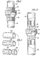
- FIGS. 1 and 2 Examples of assemblies comprising said elements are illustrated in FIGS. 1 and 2. These assemblies consist of a first element or nut 14 intended to tighten the connector, of a second element or part of this idler 16 which can be fixed to the tube 10, and of a third element or fixed part 18 which can be made integral of the tube 12.
- the elements 16 and 18 can be of the female or male type, with planar or conical coupling, and provide for the interposition or not of a lining 20, as is well known in the art. .
- the invention now offers the possibility of producing the parts mentioned above, starting from a tubular steel element of small thickness, but always of thickness greater than approximately 2 mm, which is subjected to deformation operations, in particularly under the effect of mainly axial stresses and under relatively limited forces.
- the invention provides, for most of the connection elements considered, a preliminary phase which consists in stretching a tube 22 (FIG. 3) so as to obtain a tubular element 24 comprising an outer surface of polygonal shape, in particular of octagonal shape or hexagonal with rounded edges, which allows said element to be grasped or tightened with a key of a type known on the market.
- the choice of the external conformation of the tubular element 24 and the choice of the thicknesses of the starting tube 22 are made on the one hand so as to preserve the tubular element 24 of the minimum thicknesses such that they allow subsequent operations to be carried out on this element until the desired connection piece is obtained, which of course has the desired characteristics of resistance to pressure, while on the other hand said choices are influenced also by the consideration that stretching should be carried out in a single pass, and this for reasons of economy, especially because this avoids having to resort to intermediate heat treatment operations.
- the tubular element is cut into sections of tube 26, each according to a prefixed axial dimension, for subsequent operations.
- the method of the invention provides for a local bending deformation towards the inside of the walls of the tube section 26, which is preferably done in at least two phases, as indicated in 28 and 30 in FIG. 4, until the general configuration of the element 14 is obtained, the latter being subsequently machined on its surface 32 (FIG. 4) to produce the internal thread, and, if necessary, on its surface 34 to define the diameter of the corresponding opening.
- the two deformation phases illustrated in FIG. 4 are also shown in FIG.
- the stretched tubular section 26, which has been engaged on a mandrel 36 is brought into contact with a deformation stamp or matrix with a conical configuration 38, then with a plane-shaped matrix 40, which makes it possible to fold the section 26, as shown in 28 and 30, under the ef- £ and of a stress essentially of axial compression exerted on said section.
- the matrix is designed so as to ensure the existence of a zone allowing the material a free expansion, directed radially inwards in the example illustrated, and this in order that the specific stresses cannot increase beyond the limit of deformability of the material. herself .
- the upper and lower surfaces of the element 14 will certainly include nes irregularities in shape, due to an incomplete distribution of the material, in particular the thicker parts after drawing, which are left so as not to exceed in deformation forces, and not to affect the thicknesses.
- FIG. 6 represents the operation which makes it possible to produce the element designated by 16 in FIG. 1, from the section 26 previously stretched.
- This section is first widened in the form of a socket, in its end zone 46, as shown in the figure, then this end zone is completely flattened as indicated by 48, and finally the part is machined to provide it with the thread 50 It is therefore possible to replicate the end zone 46 towards the axis of the part to obtain the part 16 as illustrated in FIG. 2.
- FIG. 7 The operations for passing from tubular section 26 to semi-worked parts 46 and 48 are shown in FIG. 7. It can be seen in this figure that the section 26 is first flared at its end by the action on this end of a die 52, which gives the product half -finished 46, as a result of which this product passes through a planar matrix 54 which makes it possible to form the semi-worked 48. As in the previous case, a mandrel 56 is inserted inside the section 26 and the latter is stressed in the axial direction, the material of the part being left free to expand at least in one zone of the matrix (in this case the expansion being directed towards the outside).
- the die 54 was established with a recess 54 ′ in which the outside edge of the flared end is lodged before closing the die of the semi-worked sleeve 46.
- This flared part is therefore driven back by the matrix 54 and is formed by crushing, so that the reduction in thickness which it had undergone during the previous phase is then compensated and the thickness reduced to the desired value.
- the weak projection 48 ′ (FIG. 6) which will remain in the region of the flanged edge of the part corresponding to the recess 54 ′, can be used to perfect the seal of the lining.
- the third element 18 illustrated in Figures 1 and 2 can be obtained, also starting from the tubular section 26, by means of a series of operations, as shown schematically in Figure 8 with reference to the conical part of the figure 2. These operations include deformation phases to obtain the semi-finished product 58, and machining phases which make it possible to produce the threads 60 ed 62 and to form the lip 72 so as to give the finished part 18 of FIG. 2 .
- the part 18 of fig. 1 is obtained by the same proceeded, but without replying the lip 72.
- the deformation is obtained as illustrated in FIG. 9, in a particular manner in several phases and, in all cases, by mounting the tubular section on a mandrel 64.
- an extender element 66 is introduced which allows slightly increase the diameter of the tubular section 26 within the limits permitted by the material.
- the semi-finished product 68 is subjected to axial deformation, the part being pushed and shaped in contact with the external stamp 70, as illustrated in the middle part of FIG. 9.
- the folded edge 72 is formed (right part of FIG. 9).
- This operation is performed not only by keeping under control the thickness of the material - to compensate for the reduction of the . stricture due to compression, to obtain higher final deformations those which would be allowed by the resistance to the plastic deformation of the material - but also and especially by using a particular technique of compression.
- the axial stress is greater than the elastic limit to the compression of the section of the section, or more precisely, to the buckling load of the individual fibers belonging to the free area of the section, situated along planes passing through the axis of the section, and subject to mutual constraints as we have in the semi-finished product 68. In this way, the free zone of bending 1 of the section can "bulge" towards the outside.
- the thickness involved is defined - within fairly limited limits and, in good substance, independently of the diameter - depending on the machining process, it follows that the length of departure from part 1 of the section 26, which is intended to be deformed to obtain the flared area of the semi-finished product 58 (that is to say the length of the section portion 26 or 62 whose diameter is varied in the matrix 70), also varies within very limited limits, and it has been experimentally observed that to obtain a half-product of type 58, this starting length must have a value around 35 mm and, in any case, less than 45 mm.
- the material is given a possibility of free expansion - with a view to carrying out the deformation under low specific stresses - in particular directed inwards, in the party designated by 74.
- the drawing is preferably carried out by making use of vidia dies having very narrow tolerances, of the order of 0.01 mm per example, while the deformation operations are carried out using a lubricant which is advantageously an anti-seize mixture consisting of oil and sulfur.
- connection elements of the above-specified type in an economically advantageous manner, these elements being able to meet all the specifications of the standardizations. in force at present, and being characterized, with respect to the connections known in the art, essentially by the fact that these elements are made of steel and that they in any case have zero draft angles.
- Another distinguishing characteristic of the connection pieces obtained according to the process of the invention, by comparison with the pieces obtained according to the known technique, is represented by the particular irregularities of their flat outer surfaces, irregularities which have been described in relation to the nut 14 but which are also found in all the other elements considered.
Abstract
Procédé fabrication d'éléments de raccorderie, à partir de tronçons de tubes coupés à mesure (22) par une déformation à froid (70,72) agissant en regard d'une partie (70) au moins de la paroi des raccords à former.Method for manufacturing fittings, from sections of tubes cut to measure (22) by cold deformation (70,72) acting opposite at least part (70) of the wall of the fittings to be formed.
Description
La présente invention est relative à un procédé pour la production industrielle d'éléments de raccorderie pour tubes, d'une manière particulière mais non exclusive, des éléments destinés à faire partie d'un ensemble de trois constituants qui forment conjointement une pièce appelée raccord permettant la liaison de deux tubes (voir, par exemple, UNI 5211/70).The present invention relates to a process for the industrial production of connection elements for tubes, in a particular but not exclusive manner, elements intended to form part of a set of three constituents which together form a part called a connection allowing the connection of two tubes (see, for example, UNI 5211/70).
On connaît bien des éléments de raccorderie de même type ou semblables à ceux qu'on vient de spécifier, dont l'emploi est très répandu et qui forment l'objet de normes d'unification. D'une manière générale, ces pièces sont obtenues sous la forme de moulages de fonte malléable que l'on soumet ensuite à un travail à la machine.Cependant, cette technique de fabrication est devenue à l'heure actuelle de plus en plus onéreuse et elle conduit en outre à l'obtention de produits d'une précision relativement peu élevée ou qui demandent d'être soumis à des opérations ultérieures de travail mécanique d'une importance considérable, donc coùteuses. De plus, la matière utilisée, qui est imposée par les conditions de formation des moulages, n'a pas montré d'être la matière idéale pour les sollecitations auxquelles les éléments de raccorderie sont assujettis en général.We know many fittings of the same type or similar to those just specified, which are widely used and which form the subject of unification standards. In general, these parts are obtained in the form of malleable cast iron which is then subjected to machine work. However, this manufacturing technique has now become increasingly expensive and it also leads to obtaining products of relatively low precision or which require to be subjected to subsequent mechanical work operations of considerable importance, and therefore costly. In addition, the material used, which is imposed by the conditions of formation of the moldings, has not shown to be the ideal material for the stresses to which the connection elements are generally subject.
Dans l'alternative, il a été déjà proposé de réaliser ces pièces de raccorderie au moyen d'opérations d'extrusion-estampage, à froid ou à chaud, exécutées à par tir d'une pastille de la matière appropriée, du laiton par exemple, dans des étampes ou matrices reproduisant la configuration finale des éléments désirés. Toutefois, si d'une part cette technique a permis d'attendre une précision remarquable par l'usage d'une matière plus approprée, elle a d'autre part posé d'autres problèmes qui ont en pratique limité notablement son utilisation dans le plan industriel. En effet, les opérations mentionnées ci-dessus mettent en jeu des forces de déformation extrêmement élevées et demandent de ce fait l'emploi d'équipements particulièrement onéreux et, ce nonobstant, de durée limitée. En outre,la matière traitée devant posséder des caractéristiques particulières, est elle-même relativement coûteuse en conséquence. De plus, à cause des puissances élevées mises en jeu,les opérations connues d'extrusion-estampage son des opérations lentes qui ne permettent d'atteindre qu'une productivité modeste.In the alternative, it has already been proposed to produce these connection pieces by means of extrusion-stamping operations, cold or hot, executed by firing a pellet of the appropriate material, brass for example , in stamps or dies reproducing the final configuration of the desired elements. However, if on the one hand this technique made it possible to wait for remarkable precision by the use of a more appropriate material, it on the other hand posed other problems which have in practice notably limited its use in the industrial plan. Indeed, the operations mentioned above involve extremely high deformation forces and therefore require the use of particularly expensive equipment and, notwithstanding, of limited duration. In addition, the treated material, which must have particular characteristics, is itself relatively expensive consequently. In addition, because of the high powers involved, the known extrusion-stamping operations are slow operations which allow only modest productivity to be achieved.
Or, le but de la présente invention est de proposer un procéde de conception nouvelle qui consent de réaliser des éléments de raccorderie du type et aux applications spécifiés ci-dessus, ces éléments ayant un degré de précision comparable à celui réalisé par l'usage desdites opérations d'extru sion-estampage, mais pouvant être fabriqués à partir d'une matière et par l'emploi d'équipements qui permettent de réduire les coûts et d'augmenter la productivité non seulement vis-à-vis dudit système d'extrusion-estampage mais aussi par rapport au moulage de fonte, et ce en utilisant une matière, telle que l'acier, qui convient mieux pour les applications envisagées.However, the object of the present invention is to propose a new design process which consents to produce connection elements of the type and for the applications specified above, these elements having a degree of precision comparable to that achieved by the use of said said extrusion-stamping operations, but which can be manufactured from a material and by the use of equipment which makes it possible to reduce costs and increase productivity not only with respect to said extrusion system - stamping but also with respect to the casting of cast iron, and this by using a material, such as steel, which is more suitable for the envisaged applications.
Les buts ci-dessus et d'autres objets de l'invention. qui apparaîtront de la description ci-après, sont d'une manière essentielle atteints grâce à l'invention au moyen d'un procédé comprenant les phases principales qui consistent: à couper à mesure un tronçon d'un tube en acier ayant une épaisseur sensiblement égale à l'épaisseur de la pièce finie; à placer ledit tronçon sur un mandrin et au contact d'une étampe ou matrice qui est établie pour agir sur une paroi dudit tronçon afin de façonner localement une partie au moins de celui-ci, en modifiant sa forme et/ou ses dimensions; à solliciter en direction sensiblement axiale ledit tronçon en vue de le façonner localement par déformation à froid dans l'étampe; à extraire de l'étampe le tronçon ainsi déformé; et à usiner certaines au moins des surfaces de ce tronçon de tube déformé.The above objects and other objects of the invention. which will appear from the description below, are essentially achieved by means of the invention by means of a process comprising the main phases which consist: in cutting a section of a steel tube having a thickness substantially equal to the thickness of the finished part; placing said section on a mandrel and in contact with a stamp or matrix which is established to act on a wall of said section in order to locally shape at least part of it, by modifying its shape and / or its dimensions; biasing said substantially axial direction in order to locally shape it by cold deformation in the stamp; extracting the section thus deformed from the stamp; and to machine at least some of the surfaces of this deformed tube section.
De préférence, on exécute les phases sus-spécifiées sur un tronçon tubulaire que l'on a préalablement soumis à une phase initiale préparatoire d'étirage qui a pour but de réaliser sur la pièce une surface extérieure octogonale ou hexagonale à arêtes arrondies, cet étirage pouvant s'effectuer en un seul passage, donc sans besoin d'avoir recours à des traitements thermiques intermédiaires.Preferably, the above-specified phases are carried out on a tubular section which has previously been subjected to an initial preparatory stretching phase which has the aim of producing on the part an octagonal or hexagonal external surface with rounded edges, this stretching. can be done in a single pass, so without the need to use intermediate heat treatments.
Selon une caractéristique particulièrement avantageuse de l'invention, chaque opération de déformation se fait dans une étampe ou matrice dans laquelle on a prévu au moins une zone de libre expansion de la matière, de telle façon que grâce aussi aux sections de plus en plus faibles chaque fois intéressées, les forces et l'énergie demandées en résultent relativement réduites et, de toutes façons, beaucoup moins importantes que celles mises en jeu dans le cas de l'extrusion-estampage utilisée jusqu'à présent.According to a particularly advantageous characteristic of the invention, each deformation operation is carried out in a stamp or matrix in which at least one zone of free expansion of the material has been provided, so that also thanks to the increasingly smaller sections Whenever interested, the forces and energy required result relatively reduced and, in any case, much less important than those involved in the case of extrusion-stamping used until now.
Selon une autre caractéristique importante de l'invention, lorsque les déformations entrainent une augmentation du diamètre de départ du tronçon tubulaire, l'épaisseur de la pièce finale à obtenir est contrôlée en compensant les diminutions d'épaisseur, qui se produiraient lors de l'étirage pour obtenir l'augmentation de diamètre, au moyen d'un refoulement de la matière, dans la même zone, réalisée par compression aciale de ladite matière. On peut de cette façon réussir à obtenir des variations dimensionnelles, en particulier des augmentations de diamètre, plus importantes que celles theoriquement permises par la résistance à la déformation plastique ou limite élastique de la metière.According to another important characteristic of the invention, when the deformations cause an increase in the starting diameter of the tubular section, the thickness of the final part to be obtained is controlled by compensating for the decreases in thickness, which would occur during the stretching to obtain the increase in diameter, by means of a discharge of the material, in the same zone, produced by acial compression of said material. In this way we can succeed in obtaining dimensional variations, in particular larger diameter increases than those theoretically allowed by the resistance to plastic deformation or elastic limit of the material.
Enfin, l'invention concerne également les pièces de raccorderie obtenues par l'application dudit procédé, ces pièces se distinguant de celles réalisables en conformité à la technique connue essentiellement par le fa'it d'être constituées en acier et de présenter des angles de dépouille nuls. Dans le cas où les filetages normaux de liaison aux tubes ne sont pas effectués, on obtient alors des éléménts nouveaux, pouvant se fixer aux tuyaux par soudage, ce qui n'était jusqu'à présent réalisable, dans le cas des raccords en fonte ou des raccords en laiton (qui sont brasés), autrement que par l'interposition de brides extrêmement encombrantes.Finally, the invention also relates to the connecting armature parts obtained by applying said process, these parts being distinguished from those attainable in accordance with the known technique essentially by fa 'it to be made from steel and have corners of draws null. In the case where the normal threads for connection to the tubes are not made, new elements are obtained, which can be fixed to the pipes by welding, which was hitherto not possible in the case of cast iron fittings or brass fittings (which are brazed), other than by interposing extremely bulky flanges.
Les nombreuses particularités et caractéristiques de l'invention seront d'ailleurs mieux comprises à la lecture de la description suivante qui se réfère à quelques exemples de mise en ceuvre donnés à titre purement illustratif/nulle- ment limitatif à l'appui des dessins annexés, dans lesquels:
- La figure 1 est une vue de face, partie en coupe, des è- léments de raccorderie pouvant être réalisés selon un mode de- mise en oeuvre de l'invention, les éléments étant représentés dans la condition assemblée d'un raccord permettant la jon - ction bout à bout ou d'extrémité, de deux tubes;
- La figure 2 est une vue correspondant à celle de figure 1 mais illustrant un raccord de type mâle, pourvu d'une lèvre d'étanchéité conique;
- La figure 3 est une vue perspective schématique illustrant les phases initiales d'étirage et de coupe d'un tube pour obtenir les éléments de raccorderie selon les figure précédentes;
- La figure 4 représente schématiquement les phases de déformation et d'usinage qui permettent d'obtenir , à partir du tronçon tubulaire de figure 3, un écrou de raccord;
- La figure 5 représente d'une manière schématique les étampes ou matrices, et les phases de déformation du tronçon tubulaire qui permettent de réaliser ledit écrou;
- La figure 6 est une vue perspective schématique, avec certaines parties en coupe, illustrant les phases de travail exécutées sur un tronçon tubulaire pour obtenir la pièce folle ou mobile du raccord de figure 1;
- La figure 7 représente schématiquement les phases et les étampes de déformation utilisées pour mettre à effet le procédé illustré à la figure 6;
- La figure 8 montre schématiquement les phases d'usinage exécutées sur un tronçon tubulaire pour réaliser la pièce fixe de figure 2, mais de type femelle;
- La figure 9 est une vue schématique illustrant les phases de déformation et les matrices correspondantes,utili sées pour la mise en oeuvre du procédé suivant la figure 8;
- les La figure 10 montre schématiquement, de la même façon que/figures 6 et 8, le procédé pour obtenir un élément de raccorderie différent, semblable à celui de figure 6 mais de type mâle, à partir cette fois d'un tube cylindrique, d'est-à-dire un tube n'ayant pas été assujetti à un étirage préalable;
- La figure 11 montre schématiquement les phases de déformation et le matrices correspondantes, employées pour mettre en oeuvre le procédé selon figure 10.
- FIG. 1 is a front view, part in section, of the connection elements which can be produced according to an embodiment of the invention, the elements being shown in the assembled condition of a connection allowing the connection - end-to-end or end ction of two tubes;
- Figure 2 is a view corresponding to that of Figure 1 but illustrating a male type connector, provided with a conical sealing lip;
- Figure 3 is a schematic perspective view illustrating the initial stages of drawing and cutting a tube to obtain the connection elements according to the preceding figures;
- FIG. 4 schematically represents the deformation and machining phases which make it possible to obtain, from the tubular section of FIG. 3, a union nut;
- FIG. 5 schematically represents the stamps or dies, and the phases of deformation of the tubular section which make it possible to produce said nut;
- Figure 6 is a schematic perspective view, with parts in section, illustrating the working phases performed on a tubular section to obtain the loose or movable part of the connector of Figure 1;
- FIG. 7 schematically represents the phases and the deformation stamps used to effect the process illustrated in FIG. 6;
- FIG. 8 schematically shows the machining phases carried out on a tubular section to produce the fixed part of FIG. 2, but of the female type;
- FIG. 9 is a schematic view illustrating the deformation phases and the corresponding dies, used for implementing the method according to FIG. 8;
- Figure 10 schematically shows, in the same way as / Figures 6 and 8, the method for obtaining a different connection element, similar to that of Figure 6 but of the male type, this time from a cylindrical tube, d 'that is to say a tube which has not been subjected to a prior stretching;
- FIG. 11 schematically shows the deformation phases and the corresponding matrices, used to implement the method according to FIG. 10.
Comme on le sait, pour réaliser la jonction, par exem ple l'union bout à bout, ou d'extrémité, de deux tubes-tels que les tubes 10 et 12 - on fait usage de raccords à plusieurs éléments om pièces, qui sont des pièces non seulement bien connues mais aussi normalisées, pour ce qui concerne certaines de leurs dimensions. Des exemples d'ensembles comprenant lesdits éléments sont illustrés aux figures 1 et 2. Ces ensembles sont constitués d'un premier élément ou écrou 14 destiné à serrer le raccord, d'un deuxième élément ou piè ce folle 16 pouvant se fixer au tube 10, et d'un troisième élément ou pièce fixe 18 qui peut être rendue solidaire du tube 12. Les éléments 16 et 18 peuvent être de type femelle ou de type mâle, avec accouplement plan ou conique, et prévoir l'interposition ou non d'une garniture 20, comme cela est bien connu de la technique de l'art.As is known, to make the junction, for example the end-to-end union, or end, of two tubes - such as
L'invention offre maintenant la possibilité de réaliser les pièces mentionnées ci-dessus, en partant d'un élément tubulaire en acier de faible épaisseur, mais toujours d'épaisseur supérieur à 2 mm environ, qui est assujetti à des opérations de déformation, en particulier sous l'effet de sollicitations principalement axiales et sous des forces relativement limitées.The invention now offers the possibility of producing the parts mentioned above, starting from a tubular steel element of small thickness, but always of thickness greater than approximately 2 mm, which is subjected to deformation operations, in particularly under the effect of mainly axial stresses and under relatively limited forces.
L'invention prévoit, pour la plupart des éléments de raccorderie considérés, une phase préalable qui consiste à étirer un tube 22 (figure 3) de façon à obtenir un élément tubulaire 24 comportant une surface extérieure de forme polygonale, en particulier de forme octogonale ou hexagonale à arêtes arrondis, qui permet audit élément d'être saisi ou serré avec une clé de type connu du marché. En vue de cette opération d'étirage, le choix de la conformation exté rieure de l'élément tubulaire 24 et le choix des épaisseurs du tube de départ 22 sont faits d'une part de manière à con server à l'élément tubulaire 24 des épaisseurs minimum telles qu'elles permettent de conduire sur cet élément les opé rations ultérieures jusqu'à en obtenir la pièce de raccorde rie désirée, dotée bien entendu des caractéristiques recher chées de résistance aux pressions, tandis que d'autre part lesdits choix sont influencés aussi par la considération qu'il convient d'effectuer l'étirage en une seule passe, et ce pour des raisons d'économie, tout spécialment par ce qu'on évite ainsi d'avoir recours à des opérations de traitement thermique intermédiaire.The invention provides, for most of the connection elements considered, a preliminary phase which consists in stretching a tube 22 (FIG. 3) so as to obtain a
A la suite de ladite opération d'étirage, l'élément tubulaire est coupé en tronçons de tube 26, chacun selon une dimension axiale préfixée, en vue des opérations ultérieures.Following said stretching operation, the tubular element is cut into sections of
Dans le cas de formation de l'écrou 14, le procédé de l'invention prévoit une déformation locale de pliage vers l'intérieur des parois du tronçon de tube 26, qui se fait de préférence en au moins deux phases, comme indiqué en 28 et 30 sur la figure 4, jusqu'à obtenir la configuration générale de l'élément 14, celui-ci étant par la suite usiné sur sa surface 32 (figure 4) pour réaliser le filetage intérieur, et, s'il le faut, sur sa surface 34 pour définir le diamètre de l'ouverture correspondante. Les deux phases de déformation illustrées à la figure 4 sont représentées aussi à la figure 5, où l'on voit que le tronçon tubulaire étiré 26, qui a été engagé sur un mandrin 36, est mis en contact avec une étampe ou matrice de déformation à configuration conique 38, puis avec une matrice de forme plane 40, qui permet de plier le tronçon 26, comme cela est montré en 28 et 30, sous l'ef- £et d'une sollicitation essentiellement de compression axia le exercée sur ledit tronçon. Ainsi qu'on peut le noter sur la figure 5, la matrice est conçue de manière à assurer l'existence d'une zone permettant à la matière une libre expansion, dirigée radialement vers l'intérieur dans l'exemple illustré, et ce afin que les sollicitations spécifiques ne puissent augmenter pas au-delà de la limite de déformabilité de la matière. elle-même . Par ailleurs, il est prévu que les surfaces supérieure et inférieure de l'élément 14 comporteront certaines irrégularités de forme, dues à une distribution incomplète de la matière, en particulier des parties plus épaisses après l'étirage, qui sont laissées pour ne pas eccéder en forces de déformation, et ne pas influer sur les épaisseurs.In the case of formation of the
En effet, et ce qu'on va dire s'applique également dans le cas des éléments décrits plus loins, l'opération de déformation du tronçon tubulaire est executée, pour sa plus grande partie, en pliant simplement la pièce, ce qui est ef fectué par l'emploi de forces relativement limitées, en vue des petites sections présentées par le tronçon tubulaire. A ces forces limitées vient en conséquence correspondre un travail réduit des presses utulisées. Ce n'est qu'a la fin de la déformation (figure 5, à droite) qu'il a lieu une phase terminale très courte au cours de laquelle la matière est as sujettie à une opération d'écrasement, celle-ci étant cependant effectuée elle-même sous l'effet de forces réduites (étant donné qu'on laisse subsister les irrégularités qui délimitent la surface sur laquelle vient agir la pression spécifique d'écrasement) et avec des courses très courtes, donc avec un travail réduit.Indeed, and what we will say also applies in the case of the elements described further on, the operation of deformation of the tubular section is carried out, for the most part, by simply bending the part, which is ef effected by the use of relatively limited forces, in view of the small sections presented by the tubular section. These limited forces consequently correspond to a reduced work of the presses used. It is only at the end of the deformation (FIG. 5, on the right) that there takes place a very short terminal phase during which the material is subjected to a crushing operation, this being however performed itself under the effect of reduced forces (given that the irregularities which delimit the surface on which the specific crushing pressure acts remain) and with very short strokes, therefore with reduced work.
La figure 6 représente l'opération qui permet de réaliser l'élément désigné par 16 à la figure 1, à partir du tronçon 26 préalablement étiré. Ce tronçon est d'abord élargi en forme de douille, dans sa zone d'extrémité 46, comme montré sur la figure, puis cette zone terminale est complètement aplatie comme indiqué par 48, et enfin la pièce est usinée pour la munir du filetage 50. Il est assi possible de réplier la zone d'extrémité 46 vers l'axe de la pièce pour obtenir la pièce 16 comme illustrée en figure 2.FIG. 6 represents the operation which makes it possible to produce the element designated by 16 in FIG. 1, from the
Les opérations pour passer du tronçon tubulaire 26 aux pièces semi-ouvrées 46 et 48 sont-représentée sur figure 7. On voit sur cette figure que le tronçon 26 est d'abord évasé à son extrémité par l'action sur cette extrémité d'une matrice 52, ce qui donne le produit demi-fini 46, à la suite de quoi ce produit passe dans une matrice plane 54 qui permet de former le semi-ouvré 48. Comme dans le cas précédent, un mandrin 56 est inséré à l'intérieur du tronçon 26 et ce dernier est sollicité en direction axiale, la matière de la pièce étant laissée libre de s'expandre au moins dans une zone de la matrice (dans ce cas l'expansion étant. dirigée vers l'extérieur).The operations for passing from
Pour assurer la conservation des épaisseurs dans la partie bridée du demi-produit 48, on a établi la matrice 54 avec un évidement 54' dans lequel vient se loger, avant la fermeture de la matrice, le bord extérieur de l'extrémité évasée en forme de douille du semi-ouvré 46. Cette partie éva sée est donc refoulée par la matrice 54 et est formée par écrasement, de façon que la réduction d'épaisseur qu'elle avait subie au cours de la phase précédente est alors compensée et l'épaisseur ramenée à la valeur désirée.To ensure the preservation of the thicknesses in the flanged part of the
La faible saillie 48' (figure 6) qui demeurera dans la région du bord bridé de la pièce correspondant à l'évidement 54', pourra servir à parfaire l'étanchéite de la garniture.The
Le troisième élément 18 illustré aux figures 1 et 2, peut être obtenu, en partant également du tronçon tubulaire 26, au moyen d'une série d'opérations, telles que représentées schématiquement à la figure 8 en référence à la pièce conique de la figure 2. Ces opérations comprennent des phases de déformation pour obtenir le demi-produit 58, et des phases d'usinage qui permettent de réaliser les filetages 60 ed 62 et de former la lèvre 72 pour donner ainsi la pièce finie 18 de la fig.2. La pièce 18 de la fig.1 est obtenue par le même procédé, mais sans réplier la lévre 72.The
La déformation est obtenue comme illustré à la figure 9, d'une manière particulière en plurieurs phases et, dans tous les cas, en montant le tronçon tubulaire sur un mandrin 64. Lors de la première phase, on introduit un élément extendeur 66 qui permet d'augmenter légèrement le diamètre du tron çon tubulaire 26 dans les limites admises par la matière.Ensuite, le semi-ouvré 68 est assujetti à déformation axiale, la pièce étant poussée et façonnée au contact de l'étampe extérieurs 70, comme illustré dans la partie de milieu de la figure 9. Enfin, le bord rabattu 72 est formé (partie droite de figure 9).The deformation is obtained as illustrated in FIG. 9, in a particular manner in several phases and, in all cases, by mounting the tubular section on a
Cette opération est exécutée non seulement en maintenant sous contrôle les épaisseurs de la matière - pour compenser la réduction dl.épaisseur due à l'augmentation de diamètre,par le refoulement dû à la compression, jusqu'à obtenir des déformations finales plus importantes que celles qui seraient permises par la résistance à la déformation plastique de la matière-mais aussi et surtout en utilisant une technique particulière de compression . En effet, afin que le semi-ouvré 68, sollicité par compression., puisse se déformer jusqu'à venir exactement épouser la forme de l'étampe extérieure 70, il est nécessaire que, selon l'invention, la sollicitation axiale soit supérieure à la limite élastique à la compression de la section du tronçon, ou plus précisément, à la charge de flambage des fibres individuelles appartenant à la zone libre du tronçon, situées selon des plans passant par l'axe du tronçon, et assujietties aux contraintes mutuelles que l'on a dans le produit demi-fini 68. De cette façon, la zone libre de fléchir 1 du tronçon peut "bomber" vers l'extérieur. Il est toutefois encore nécessaire, en vue de l'adaptation du semi-ouvré à la forme extérieure de l'étampe 70, que la déformation se produise d'une manière symmétrique au centre donc sous une charge inférieure à la charge de flambage de ladite zone de libre fléchissement 1 (considérée dans son ensemble) du tronçon, et en respectant certaines relations de "fréquence", plus précisément de "amplitude d'onde", lesquelles dépendent de l'e-paisseur de la matière et, en moindre partie, du diamètre du tronçon de départ du demi-produit. Etant donné que dans les relations de ce type, l'épaisseur entrant en jeu est définie- dans des limites assez restreintes et, en bonne substance, indépendamment du diamètre - en fonction du procédé d'usinage, il s'ensuit que la longueur de départ de la partie 1 du tronçon 26, qui est destinée à être déformée pour obtenir la zone évasée du semi-ouvré 58 (c'est-à-dire la longueur de la partie de tronçon 26 ou 62 dont le diamètre est varié dans la matrice 70), varie elle aussi dans des limites très restreintes, et l'on a expérimentalement constaté que pour obtenir un demiproduit du type 58, il faut que cette longueur de départ ait une valeur aux environs de 35 mm et, de toutes façons,inférieure à 45 mm.This operation is performed not only by keeping under control the thickness of the material - to compensate for the reduction of the .épaisseur due to increase in diameter by repression due to compression, to obtain higher final deformations those which would be allowed by the resistance to the plastic deformation of the material - but also and especially by using a particular technique of compression. In fact, so that the
On a en effet constaté avec surprise qu'au-dehors desdites limites il était impossible d'obtenir une déformation du tronçon 26 permettant à la paroi extérieure de ce tronçon d'épouser parfaitement la forme de l'étampe 70 et ce, bien entendu, en maintenant les épaisseurs et les autres conditions opérationelles nécessaires.It has indeed been surprisingly found that outside of said limits it was impossible to obtain a deformation of the
De toute façon, aussi dans le cas de la déformation selon la figure 9, on donne à la matière une possibilité de libre expansion-en vue d'effectuer la déformation sous de faibles sollicitations spécifiques - en particulier dirigée vers l'intérieur, dans la partie désignée par 74.In any case, also in the case of the deformation according to FIG. 9, the material is given a possibility of free expansion - with a view to carrying out the deformation under low specific stresses - in particular directed inwards, in the party designated by 74.
Dans le cas de pièces de type mâle, il est possible de prévoir une succession de phases opérationnelles qui sont exécutées au départ d'un tronçon tubulaire 76 (figure 10) non assujetti à étirage préalable. Ce tronçon est d'abord déformé au moyen d'un mandrin intérieur 78 et par l'action d'une matrice extérieure 80 (figure 11) en vue d'obtenir la zone polygonale 82, puis la lèvre supérieure du semi-ouvré 84 est pliée comme illustré dans les parties de milieu et de droite de figure 11, substantiellement sur la base des principes exposés plus haut en référence aux figures 6 et 7,après quoi la partie cylindrique du demi-produit 84 est usinée pour y former le filetage 86.In the case of male parts, it is possible to provide a succession of operational phases which are carried out from a tubular section 76 (Figure 10) not subject to prior stretching. This section is first deformed by means of an
Quant aux autres modalités de mise en oeuvre des opérations considérées, il y a lieu à noter qu'on effectue de préférence l'étirage en faisant usage de filières en vidia ayant des tolérances très étroites, de l'ordre de 0,01 mm par exemple, tandis qu'on conduit les opérations de déformation en utilisant un lubrificant qui est d'une manière avantageuse un mélange antigrippant constitué d'huile et de soufre.As for the other methods of carrying out the operations considered, it should be noted that the drawing is preferably carried out by making use of vidia dies having very narrow tolerances, of the order of 0.01 mm per example, while the deformation operations are carried out using a lubricant which is advantageously an anti-seize mixture consisting of oil and sulfur.
Par l'application du procédé décrit dans ce qui précé- de, il devient possible d'obtenir des éléments de raccorderie du type sus-spécifié d'une manière économiquement avantageuse, ces éléments étant en état de satisfaire à toutes les .spécifications des normalisations en vigueur à présent, et étant caractérisés, vis-à-vis des raccorderies connues de l'art, essentiellement par le fait que ces éléments sont constitués en acier et qu'ils présentent en tous cas des angles de dépouille nuls. Une autre caractéristique distinctive des pièces de raccorderie obtenues selon la procédé de l'invention, par comparaison avec les pièces obtenues selon la technique connue, est représentée par les irrégularités particulières de leurs surfaces planes extérieures, irrégularités qu'on a décrites en relation à l'écrou 14 mais qui se trouvent aussi dans tous les autres éléments considérés.By applying the method described in the foregoing, it becomes possible to obtain connection elements of the above-specified type in an economically advantageous manner, these elements being able to meet all the specifications of the standardizations. in force at present, and being characterized, with respect to the connections known in the art, essentially by the fact that these elements are made of steel and that they in any case have zero draft angles. Another distinguishing characteristic of the connection pieces obtained according to the process of the invention, by comparison with the pieces obtained according to the known technique, is represented by the particular irregularities of their flat outer surfaces, irregularities which have been described in relation to the
Il est de plus possible de réaliser, en faisant cependant abstraction des normalisations en matière, des pièces fixes et folles qui ne comportent pas de filetage de liaison avec le tube. Ces pièces, qui représentent un produit nouveau, peuvent. d'une manière avantageuse et économique se fixer par soudage au tube, ce qui maintenant seulement est rendu possible grâce aux raccords en acier selon la présente invention.It is moreover possible to produce, however disregarding the standardizations in the matter, fixed and loose parts which do not include a thread for connection with the tube. These parts, which represent a new product, can. advantageously and economically be fixed by welding to the tube, which now only is made possible thanks to the steel fittings according to the present invention.
Comme on l'a dit au préalable, les usinages de ces éléments consistent pour la plupart en des pliages et, dans le cas des éléments plus compliqués tels que les écrous (figures 4 et 5) et les pièces folles (figures 6,7,10 et 11), en un écrasement partiel exécuté uniquement sur la section torique de la surface d'about ou de choc.Vis-à-vis des opérations traditionnelles d'estampage de pièces semblables, la matière travaillée étant la méme, on a un rapport favorable de sections de travail compris entre 1/5 et 1/10.As we said before, the machining of these elements consists mostly of bending and, in the case of more complicated elements such as nuts (Figures 4 and 5) and loose parts (Figures 6,7, 10 and 11), in a partial crushing performed only on the toric section of the butt or impact surface. With respect to traditional stamping operations on similar parts, the material worked being the same, there is a favorable ratio of working sections between 1/5 and 1/10.
Le recours à l'écrasement ayant uniquement pour but de planer partiellement les surfaces d'appui, avec des courses de travail comprises dans l'intervalle de 0,5-1,5 mm, il s'ensuit que l'énergie dépensée pour ces opérations demeure dans un rapport de 1/25-1/50, vis-à-vis de l'estampage traditionnel.The recourse to crushing having only the aim of partially planing the bearing surfaces, with working strokes in the range of 0.5-1.5 mm, it follows that the energy expended for these operations remains in a ratio of 1 / 25-1 / 50, vis-à-vis traditional stamping.
Par rapport à des pièces semblables, réalisées par estampage de fer, on fait usage de presses de puissance 1/5-1/10 fois plus petite:, et avec des vitesses de travail 5 fois plus élevées: il en résulte un coût d'intestissement plus bas, avec une productivité plus importante.Compared to similar parts, produced by stamping iron, we use presses with power 1 / 5-1 / 10 times smaller :, and with working speeds 5 times higher: this results in a cost of lower intesting, with higher productivity.
Bien entendu, plusieurs modifications et variantes pourront être apportées aux modes de mise en oeuvre décrits ci-dessus,sans sortir pour autant du domaine de l'invention.Of course, several modifications and variants may be made to the embodiments described above, without however departing from the scope of the invention.
Claims (14)
Priority Applications (1)
| Application Number | Priority Date | Filing Date | Title |
|---|---|---|---|
| AT81830162T ATE19979T1 (en) | 1980-09-24 | 1981-09-16 | PROCEDURE FOR MAKING A CONNECTION NIPPLE. |
Applications Claiming Priority (2)
| Application Number | Priority Date | Filing Date | Title |
|---|---|---|---|
| IT24878/80A IT1133613B (en) | 1980-09-24 | 1980-09-24 | PROCEDURE FOR THE CREATION OF PIPE FITTING COMPONENTS, AND COMPONENTS SO OBTAINED |
| IT2487880 | 1980-09-24 |
Publications (2)
| Publication Number | Publication Date |
|---|---|
| EP0048701A1 true EP0048701A1 (en) | 1982-03-31 |
| EP0048701B1 EP0048701B1 (en) | 1986-05-28 |
Family
ID=11215015
Family Applications (1)
| Application Number | Title | Priority Date | Filing Date |
|---|---|---|---|
| EP81830162A Expired EP0048701B1 (en) | 1980-09-24 | 1981-09-16 | Method of making pipe unions |
Country Status (5)
| Country | Link |
|---|---|
| US (1) | US4452063A (en) |
| EP (1) | EP0048701B1 (en) |
| AT (1) | ATE19979T1 (en) |
| DE (1) | DE3174718D1 (en) |
| IT (1) | IT1133613B (en) |
Families Citing this family (15)
| Publication number | Priority date | Publication date | Assignee | Title |
|---|---|---|---|---|
| DE3517163A1 (en) * | 1985-05-11 | 1986-11-13 | Aeroquip GmbH, 7570 Baden-Baden | METHOD FOR PRODUCING A HOSE NIPPLE FOR HYDRAULICALLY LOADED PRESS OR SCREW FITTINGS |
| US5165168A (en) * | 1991-04-09 | 1992-11-24 | Higgins Larry B | Method of making a high rise spout and spout made according to the method |
| CA2070857C (en) * | 1991-07-23 | 2003-12-02 | Michel Gautheron | Post molding wedge forming process for pivot joint internal bushing ends, and applications |
| US5341668A (en) * | 1992-12-30 | 1994-08-30 | Corning Incorporated | Method of forming a vessel pouring spout |
| US6808210B1 (en) | 1997-09-03 | 2004-10-26 | The Charles Machine Works, Inc. | Drill pipe with upset ends having constant wall thickness and method for making same |
| USD406639S (en) * | 1998-04-29 | 1999-03-09 | H&H Tube & Manufacturing Co. | Spout design |
| GB2356909B (en) * | 1999-12-01 | 2003-11-12 | Esser Werke Gmbh & Co Kg | Tube for conveying solids |
| US6397652B1 (en) | 2000-03-22 | 2002-06-04 | The Sollami Company | Tool body and method of manufacture |
| CN101817028B (en) * | 2010-03-30 | 2012-12-26 | 宁波市鄞州剑均机械科技有限公司 | Cold extrusion mould for double-head pipe joint |
| CN101817027B (en) * | 2010-03-30 | 2012-01-25 | 宁波东港紧固件制造有限公司 | Cold extrusion mould for double-head pipe joint |
| US20120256412A1 (en) * | 2011-04-08 | 2012-10-11 | Seung Oh | Joint member manufactured using pipe and manufacturing method of the same |
| DE102012211311A1 (en) * | 2012-06-29 | 2014-01-02 | Behr Gmbh & Co. Kg | Exhaust gas heat exchanger |
| US9670951B2 (en) * | 2014-04-08 | 2017-06-06 | A.A.M International S.A.R.L. | Variable-wall light-weight axle shaft with an integral flange member and method for making the same |
| DE102014208093A1 (en) * | 2014-04-29 | 2015-10-29 | Mahle Lnternational Gmbh | Heat exchanger |
| US9630451B2 (en) | 2014-06-18 | 2017-04-25 | American Axle & Manufacturing, Inc. | Method of manufacturing hollow axle shaft for a vehicle |
Citations (6)
| Publication number | Priority date | Publication date | Assignee | Title |
|---|---|---|---|---|
| US1408390A (en) * | 1919-02-17 | 1922-02-28 | Nordlund August | Process of forming pipe unions |
| FR567611A (en) * | 1923-06-19 | 1924-03-07 | Usines De Fabrication De Tubes | Process for fitting metal tubes and resulting products with double flanges |
| US3109479A (en) * | 1959-06-05 | 1963-11-05 | Penn Aircraft Products Inc | Flaring tool |
| US3266822A (en) * | 1961-08-21 | 1966-08-16 | Price Pfister Brass Mfg | Metal forming process for shaping ends of tubes and the product thereof |
| DE1625981B1 (en) * | 1967-12-18 | 1970-06-25 | Danfoss As | Process for the production of a connection nipple and a union nut and the corresponding fitting |
| FR2379331A1 (en) * | 1977-02-07 | 1978-09-01 | Gould Inc | FLARING TOOL |
Family Cites Families (2)
| Publication number | Priority date | Publication date | Assignee | Title |
|---|---|---|---|---|
| US1142782A (en) * | 1914-12-03 | 1915-06-08 | Rockwood Sprinkler Co | Set of dies. |
| EP0013040A1 (en) * | 1978-12-12 | 1980-07-09 | Polva-Nederland B.V. | Method and apparatus for forming couplings of thermoplastic material |
-
1980
- 1980-09-24 IT IT24878/80A patent/IT1133613B/en active
-
1981
- 1981-09-16 EP EP81830162A patent/EP0048701B1/en not_active Expired
- 1981-09-16 AT AT81830162T patent/ATE19979T1/en active
- 1981-09-16 DE DE8181830162T patent/DE3174718D1/en not_active Expired
- 1981-09-22 US US06/304,812 patent/US4452063A/en not_active Expired - Fee Related
Patent Citations (6)
| Publication number | Priority date | Publication date | Assignee | Title |
|---|---|---|---|---|
| US1408390A (en) * | 1919-02-17 | 1922-02-28 | Nordlund August | Process of forming pipe unions |
| FR567611A (en) * | 1923-06-19 | 1924-03-07 | Usines De Fabrication De Tubes | Process for fitting metal tubes and resulting products with double flanges |
| US3109479A (en) * | 1959-06-05 | 1963-11-05 | Penn Aircraft Products Inc | Flaring tool |
| US3266822A (en) * | 1961-08-21 | 1966-08-16 | Price Pfister Brass Mfg | Metal forming process for shaping ends of tubes and the product thereof |
| DE1625981B1 (en) * | 1967-12-18 | 1970-06-25 | Danfoss As | Process for the production of a connection nipple and a union nut and the corresponding fitting |
| FR2379331A1 (en) * | 1977-02-07 | 1978-09-01 | Gould Inc | FLARING TOOL |
Also Published As
| Publication number | Publication date |
|---|---|
| IT1133613B (en) | 1986-07-09 |
| ATE19979T1 (en) | 1986-06-15 |
| IT8024878A0 (en) | 1980-09-24 |
| DE3174718D1 (en) | 1986-07-03 |
| EP0048701B1 (en) | 1986-05-28 |
| US4452063A (en) | 1984-06-05 |
Similar Documents
| Publication | Publication Date | Title |
|---|---|---|
| EP0048701A1 (en) | Method of making pipe unions | |
| FR2495508A1 (en) | PROCESS FOR MANUFACTURING PULLEYS BY ROLLING FROM A METAL SHEET AND PULLEYS THUS OBTAINED | |
| WO2010046587A1 (en) | Polygonal driving means with inbuilt collar | |
| FR2760265A1 (en) | METHOD FOR IMPROVING FATIGUE RESISTANCE DUE TO REPEATED PRESSURES IN A BYPASS FOR HIGH-PRESSURE FLUID, DERIVATIVE CONDUIT OBTAINED AND ELEMENT WITH ADJUSTED SLIDING RING | |
| CH631534A5 (en) | CONNECTION DEVICE AND METHOD FOR THE PRODUCTION THEREOF. | |
| FR2498954A1 (en) | METHOD FOR MAKING THE BEARING SLEEVE WITHOUT CHIPS WITH INNER BACKGROUND OR BOTTOM PART | |
| EP0013040A1 (en) | Method and apparatus for forming couplings of thermoplastic material | |
| EP0056776A1 (en) | Method of manufacturing hollow one-piece axle blanks, and axle blanks obtained | |
| EP0014107B1 (en) | Method of manufacturing a cylindrical sleeve with inner grooves, closed at least at one end | |
| EP0310726B1 (en) | Manufacturing method of conical metal boxes and tool for carrying out this method | |
| WO2014135772A1 (en) | Tool for forming a collar at one end of a tube | |
| EP0159242B1 (en) | Steel tube joint, tooling and method of obtaining greater precision | |
| EP1473503B1 (en) | Corrugated flexible pipe with a reinforcing metal ring and method for manufacturing said pipe. | |
| BE849516A (en) | FRICTION WELDING PROCESS | |
| FR2937568A1 (en) | METHOD FOR MANUFACTURING A BOLT PART, TOOL FOR CARRYING OUT THE METHOD, DEVICE FOR TIGHTENING AND BLEEDING SUCH A BOLT PART | |
| FR2474908A1 (en) | CLOSED CHAMBER EXTRUSION METHOD AND DEVICE FOR CONFIGURING A METAL ROD IN A TULIP-SHAPED WORKPIECE | |
| FR2544806A1 (en) | Method of assembling two coaxial components of revolution, of the same diameter | |
| FR2498006A1 (en) | METHOD OF MANUFACTURING CYLINDERS FOR ANODES OF ELECTRONIC TUBES | |
| FR2599647A1 (en) | Process for manufacturing a gear-change lever and lever obtained | |
| FR2777213A1 (en) | METHOD FOR MANUFACTURING METAL TUBULAR PIECE AND COMPOSITE TUBULAR SHAFT | |
| FR2483809A1 (en) | METHOD AND INSTALLATION FOR MANUFACTURING TUBES ON TUBE STRETCH BENCHES | |
| FR2604930A1 (en) | CYLINDER OF DRESSER MACHINES | |
| EP1598567A1 (en) | Method for assembling a press rivet and press rivet obtained by such a method | |
| FR2666179A1 (en) | PROCESS FOR MOUNTING THE FIXING COLLAR OF A PLUG CONNECTOR. | |
| FR2652773A1 (en) | Method of obtaining a flanged bush, especially intended for the connection of a pipe to a coupling, and device for its implementation |
Legal Events
| Date | Code | Title | Description |
|---|---|---|---|
| PUAI | Public reference made under article 153(3) epc to a published international application that has entered the european phase |
Free format text: ORIGINAL CODE: 0009012 |
|
| AK | Designated contracting states |
Designated state(s): AT BE DE FR GB NL |
|
| 17P | Request for examination filed |
Effective date: 19820924 |
|
| GRAA | (expected) grant |
Free format text: ORIGINAL CODE: 0009210 |
|
| AK | Designated contracting states |
Kind code of ref document: B1 Designated state(s): AT BE DE FR GB NL |
|
| PG25 | Lapsed in a contracting state [announced via postgrant information from national office to epo] |
Ref country code: NL Effective date: 19860528 Ref country code: AT Effective date: 19860528 |
|
| REF | Corresponds to: |
Ref document number: 19979 Country of ref document: AT Date of ref document: 19860615 Kind code of ref document: T |
|
| REF | Corresponds to: |
Ref document number: 3174718 Country of ref document: DE Date of ref document: 19860703 |
|
| PG25 | Lapsed in a contracting state [announced via postgrant information from national office to epo] |
Ref country code: BE Effective date: 19860930 |
|
| NLV1 | Nl: lapsed or annulled due to failure to fulfill the requirements of art. 29p and 29m of the patents act | ||
| BERE | Be: lapsed |
Owner name: SEBASTIANI ENRICO Effective date: 19860930 |
|
| PLBE | No opposition filed within time limit |
Free format text: ORIGINAL CODE: 0009261 |
|
| STAA | Information on the status of an ep patent application or granted ep patent |
Free format text: STATUS: NO OPPOSITION FILED WITHIN TIME LIMIT |
|
| 26N | No opposition filed | ||
| PGFP | Annual fee paid to national office [announced via postgrant information from national office to epo] |
Ref country code: FR Payment date: 19890920 Year of fee payment: 9 |
|
| PGFP | Annual fee paid to national office [announced via postgrant information from national office to epo] |
Ref country code: GB Payment date: 19890930 Year of fee payment: 9 |
|
| PGFP | Annual fee paid to national office [announced via postgrant information from national office to epo] |
Ref country code: DE Payment date: 19891012 Year of fee payment: 9 |
|
| PG25 | Lapsed in a contracting state [announced via postgrant information from national office to epo] |
Ref country code: GB Effective date: 19900916 |
|
| GBPC | Gb: european patent ceased through non-payment of renewal fee | ||
| PG25 | Lapsed in a contracting state [announced via postgrant information from national office to epo] |
Ref country code: FR Effective date: 19910530 |
|
| PG25 | Lapsed in a contracting state [announced via postgrant information from national office to epo] |
Ref country code: DE Effective date: 19910601 |
|
| REG | Reference to a national code |
Ref country code: FR Ref legal event code: ST |