EP0047359B1 - Heating hydrocarbons in a tubular heater - Google Patents
Heating hydrocarbons in a tubular heater Download PDFInfo
- Publication number
- EP0047359B1 EP0047359B1 EP81104097A EP81104097A EP0047359B1 EP 0047359 B1 EP0047359 B1 EP 0047359B1 EP 81104097 A EP81104097 A EP 81104097A EP 81104097 A EP81104097 A EP 81104097A EP 0047359 B1 EP0047359 B1 EP 0047359B1
- Authority
- EP
- European Patent Office
- Prior art keywords
- combustion gas
- heat exchange
- side walls
- radiant chamber
- floor
- Prior art date
- Legal status (The legal status is an assumption and is not a legal conclusion. Google has not performed a legal analysis and makes no representation as to the accuracy of the status listed.)
- Expired
Links
Images

Classifications
-
- F—MECHANICAL ENGINEERING; LIGHTING; HEATING; WEAPONS; BLASTING
- F23—COMBUSTION APPARATUS; COMBUSTION PROCESSES
- F23C—METHODS OR APPARATUS FOR COMBUSTION USING FLUID FUEL OR SOLID FUEL SUSPENDED IN A CARRIER GAS OR AIR
- F23C1/00—Combustion apparatus specially adapted for combustion of two or more kinds of fuel simultaneously or alternately, at least one kind of fuel being either a fluid fuel or a solid fuel suspended in a carrier gas or air
-
- C—CHEMISTRY; METALLURGY
- C01—INORGANIC CHEMISTRY
- C01B—NON-METALLIC ELEMENTS; COMPOUNDS THEREOF; METALLOIDS OR COMPOUNDS THEREOF NOT COVERED BY SUBCLASS C01C
- C01B3/00—Hydrogen; Gaseous mixtures containing hydrogen; Separation of hydrogen from mixtures containing it; Purification of hydrogen; Reversible storage of hydrogen
- C01B3/02—Production of hydrogen; Production of gaseous mixtures containing hydrogen
- C01B3/32—Production of hydrogen; Production of gaseous mixtures containing hydrogen by reaction of gaseous or liquid organic compounds with gasifying agents, e.g. water, carbon dioxide or air
- C01B3/34—Production of hydrogen; Production of gaseous mixtures containing hydrogen by reaction of gaseous or liquid organic compounds with gasifying agents, e.g. water, carbon dioxide or air by reaction of hydrocarbons with gasifying agents
- C01B3/38—Production of hydrogen; Production of gaseous mixtures containing hydrogen by reaction of gaseous or liquid organic compounds with gasifying agents, e.g. water, carbon dioxide or air by reaction of hydrocarbons with gasifying agents using catalysts
- C01B3/384—Production of hydrogen; Production of gaseous mixtures containing hydrogen by reaction of gaseous or liquid organic compounds with gasifying agents, e.g. water, carbon dioxide or air by reaction of hydrocarbons with gasifying agents using catalysts with external heating of the catalyst
-
- B—PERFORMING OPERATIONS; TRANSPORTING
- B01—PHYSICAL OR CHEMICAL PROCESSES OR APPARATUS IN GENERAL
- B01J—CHEMICAL OR PHYSICAL PROCESSES, e.g. CATALYSIS OR COLLOID CHEMISTRY; THEIR RELEVANT APPARATUS
- B01J8/00—Chemical or physical processes in general, conducted in the presence of fluids and solid particles; Apparatus for such processes
- B01J8/02—Chemical or physical processes in general, conducted in the presence of fluids and solid particles; Apparatus for such processes with stationary particles, e.g. in fixed beds
- B01J8/06—Chemical or physical processes in general, conducted in the presence of fluids and solid particles; Apparatus for such processes with stationary particles, e.g. in fixed beds in tube reactors; the solid particles being arranged in tubes
- B01J8/062—Chemical or physical processes in general, conducted in the presence of fluids and solid particles; Apparatus for such processes with stationary particles, e.g. in fixed beds in tube reactors; the solid particles being arranged in tubes being installed in a furnace
-
- C—CHEMISTRY; METALLURGY
- C01—INORGANIC CHEMISTRY
- C01B—NON-METALLIC ELEMENTS; COMPOUNDS THEREOF; METALLOIDS OR COMPOUNDS THEREOF NOT COVERED BY SUBCLASS C01C
- C01B2203/00—Integrated processes for the production of hydrogen or synthesis gas
- C01B2203/02—Processes for making hydrogen or synthesis gas
- C01B2203/0205—Processes for making hydrogen or synthesis gas containing a reforming step
- C01B2203/0227—Processes for making hydrogen or synthesis gas containing a reforming step containing a catalytic reforming step
- C01B2203/0233—Processes for making hydrogen or synthesis gas containing a reforming step containing a catalytic reforming step the reforming step being a steam reforming step
-
- C—CHEMISTRY; METALLURGY
- C01—INORGANIC CHEMISTRY
- C01B—NON-METALLIC ELEMENTS; COMPOUNDS THEREOF; METALLOIDS OR COMPOUNDS THEREOF NOT COVERED BY SUBCLASS C01C
- C01B2203/00—Integrated processes for the production of hydrogen or synthesis gas
- C01B2203/06—Integration with other chemical processes
- C01B2203/062—Hydrocarbon production, e.g. Fischer-Tropsch process
-
- C—CHEMISTRY; METALLURGY
- C01—INORGANIC CHEMISTRY
- C01B—NON-METALLIC ELEMENTS; COMPOUNDS THEREOF; METALLOIDS OR COMPOUNDS THEREOF NOT COVERED BY SUBCLASS C01C
- C01B2203/00—Integrated processes for the production of hydrogen or synthesis gas
- C01B2203/08—Methods of heating or cooling
- C01B2203/0805—Methods of heating the process for making hydrogen or synthesis gas
- C01B2203/0811—Methods of heating the process for making hydrogen or synthesis gas by combustion of fuel
-
- C—CHEMISTRY; METALLURGY
- C01—INORGANIC CHEMISTRY
- C01B—NON-METALLIC ELEMENTS; COMPOUNDS THEREOF; METALLOIDS OR COMPOUNDS THEREOF NOT COVERED BY SUBCLASS C01C
- C01B2203/00—Integrated processes for the production of hydrogen or synthesis gas
- C01B2203/08—Methods of heating or cooling
- C01B2203/0805—Methods of heating the process for making hydrogen or synthesis gas
- C01B2203/0811—Methods of heating the process for making hydrogen or synthesis gas by combustion of fuel
- C01B2203/0816—Heating by flames
-
- C—CHEMISTRY; METALLURGY
- C01—INORGANIC CHEMISTRY
- C01B—NON-METALLIC ELEMENTS; COMPOUNDS THEREOF; METALLOIDS OR COMPOUNDS THEREOF NOT COVERED BY SUBCLASS C01C
- C01B2203/00—Integrated processes for the production of hydrogen or synthesis gas
- C01B2203/08—Methods of heating or cooling
- C01B2203/0805—Methods of heating the process for making hydrogen or synthesis gas
- C01B2203/0838—Methods of heating the process for making hydrogen or synthesis gas by heat exchange with exothermic reactions, other than by combustion of fuel
- C01B2203/0844—Methods of heating the process for making hydrogen or synthesis gas by heat exchange with exothermic reactions, other than by combustion of fuel the non-combustive exothermic reaction being another reforming reaction as defined in groups C01B2203/02 - C01B2203/0294
-
- C—CHEMISTRY; METALLURGY
- C01—INORGANIC CHEMISTRY
- C01B—NON-METALLIC ELEMENTS; COMPOUNDS THEREOF; METALLOIDS OR COMPOUNDS THEREOF NOT COVERED BY SUBCLASS C01C
- C01B2203/00—Integrated processes for the production of hydrogen or synthesis gas
- C01B2203/08—Methods of heating or cooling
- C01B2203/0805—Methods of heating the process for making hydrogen or synthesis gas
- C01B2203/0866—Methods of heating the process for making hydrogen or synthesis gas by combination of different heating methods
-
- C—CHEMISTRY; METALLURGY
- C01—INORGANIC CHEMISTRY
- C01B—NON-METALLIC ELEMENTS; COMPOUNDS THEREOF; METALLOIDS OR COMPOUNDS THEREOF NOT COVERED BY SUBCLASS C01C
- C01B2203/00—Integrated processes for the production of hydrogen or synthesis gas
- C01B2203/12—Feeding the process for making hydrogen or synthesis gas
- C01B2203/1205—Composition of the feed
- C01B2203/1211—Organic compounds or organic mixtures used in the process for making hydrogen or synthesis gas
- C01B2203/1235—Hydrocarbons
- C01B2203/1241—Natural gas or methane
-
- C—CHEMISTRY; METALLURGY
- C01—INORGANIC CHEMISTRY
- C01B—NON-METALLIC ELEMENTS; COMPOUNDS THEREOF; METALLOIDS OR COMPOUNDS THEREOF NOT COVERED BY SUBCLASS C01C
- C01B2203/00—Integrated processes for the production of hydrogen or synthesis gas
- C01B2203/12—Feeding the process for making hydrogen or synthesis gas
- C01B2203/1205—Composition of the feed
- C01B2203/1211—Organic compounds or organic mixtures used in the process for making hydrogen or synthesis gas
- C01B2203/1235—Hydrocarbons
- C01B2203/1247—Higher hydrocarbons
-
- C—CHEMISTRY; METALLURGY
- C10—PETROLEUM, GAS OR COKE INDUSTRIES; TECHNICAL GASES CONTAINING CARBON MONOXIDE; FUELS; LUBRICANTS; PEAT
- C10G—CRACKING HYDROCARBON OILS; PRODUCTION OF LIQUID HYDROCARBON MIXTURES, e.g. BY DESTRUCTIVE HYDROGENATION, OLIGOMERISATION, POLYMERISATION; RECOVERY OF HYDROCARBON OILS FROM OIL-SHALE, OIL-SAND, OR GASES; REFINING MIXTURES MAINLY CONSISTING OF HYDROCARBONS; REFORMING OF NAPHTHA; MINERAL WAXES
- C10G2400/00—Products obtained by processes covered by groups C10G9/00 - C10G69/14
- C10G2400/20—C2-C4 olefins
-
- C—CHEMISTRY; METALLURGY
- C10—PETROLEUM, GAS OR COKE INDUSTRIES; TECHNICAL GASES CONTAINING CARBON MONOXIDE; FUELS; LUBRICANTS; PEAT
- C10G—CRACKING HYDROCARBON OILS; PRODUCTION OF LIQUID HYDROCARBON MIXTURES, e.g. BY DESTRUCTIVE HYDROGENATION, OLIGOMERISATION, POLYMERISATION; RECOVERY OF HYDROCARBON OILS FROM OIL-SHALE, OIL-SAND, OR GASES; REFINING MIXTURES MAINLY CONSISTING OF HYDROCARBONS; REFORMING OF NAPHTHA; MINERAL WAXES
- C10G2400/00—Products obtained by processes covered by groups C10G9/00 - C10G69/14
- C10G2400/26—Fuel gas
-
- Y—GENERAL TAGGING OF NEW TECHNOLOGICAL DEVELOPMENTS; GENERAL TAGGING OF CROSS-SECTIONAL TECHNOLOGIES SPANNING OVER SEVERAL SECTIONS OF THE IPC; TECHNICAL SUBJECTS COVERED BY FORMER USPC CROSS-REFERENCE ART COLLECTIONS [XRACs] AND DIGESTS
- Y10—TECHNICAL SUBJECTS COVERED BY FORMER USPC
- Y10S—TECHNICAL SUBJECTS COVERED BY FORMER USPC CROSS-REFERENCE ART COLLECTIONS [XRACs] AND DIGESTS
- Y10S585/00—Chemistry of hydrocarbon compounds
- Y10S585/919—Apparatus considerations
- Y10S585/921—Apparatus considerations using recited apparatus structure
- Y10S585/924—Reactor shape or disposition
- Y10S585/925—Dimension or proportion
Definitions
- This invention relates to fired, tubular furnaces for heating hydrocarbons. More specifically, the invention relates to a process and apparatus for heating hydrocarbons in furnaces employing vertical tubes wherein combustion gas is passed upwardly through the radiant chamber of the heater or furnace.
- Vertical tube, fired heaters are well known in the petroleum and chemical process industries and are utilized to heat hydrocarbon feed streams in a variety of processes such as distillation, thermal cracking, visbreaking, and, of particular interest here, steam cracking and steam reforming (cf. for example GB-A-974 178, DE-B-1 601 235).
- Heater design is governed by the objectives of the particular process as well as the general objective of high furnace efficiency, that is, the amount of heat absorbed by the process fluid divided by the heating value of fuel input to furnace.
- process furnace design see Perry and Chilton, "Chemical Engineers Handbook", Fifth Edition, McGraw-Hill Book Company, pp. 9-34 to 9-38.
- a very high, uniform heat flux from combustion gas to process fluid is utilized to bring the fluid quickly to a cracking temperature in the range of from about 815°C to about 925°C.
- the high, uniform heat flux requirement is normally achieved through use of back-mixed combustion gas conditions throughout the radiant chamber, that is, approximating a well-stirred reactor.
- the back-mixed combustion gas condition is brought about by turbulent heat input from a plurality of burners mounted in the radiant chamber enclosure.
- a conventional arrangement for achieving this is through use of sidewall burners in optional combination with floor burners in a box type radiant chamber wherein combustion gas passes upwardly through the radiant chamber to a convection section.
- a process and apparatus are provided for heating hydrocarbons by indirect heat exchange with combustion gas in the radiant chamber of a fired tubular heater having a plurality of straight, vertical, tubular heat exchange means in single pass heat exchange relationship with the combustion gas wherein the combustion gas passing over the lower portions of the tubular heat exchange means is predominantly in a back-mixed, i.e. - well-stirred, flow condition and the combustion gas passing over the upper portions thereof is predominantly in a plug-flow condition, i.e. - substantially each gas particle having approximately the same residence time.
- Radiant chamber 201 is formed by horizontal floor 202, opposed vertical end walls 203 (see Figure 2A) contiguous with the floor, opposed vertical lower side walls 204 that are contiguous with the floor 202 and end walls 203, opposed intermediate side walls 205 contiguous with end walls 203 and lower side walls 204 and which slope inwardly at an angle from about 10 to about 30 degrees, preferably from about 10 to about 20 degrees, from a plane projected by upward extension of the lower side walls.
- the upper portion of radiant chamber 201 has combustion gas outlet means 206 which is contiguous with end walls 203 and intermediate side walls 205.
- the combustion gas outlet means 206 is formed by an extension of end walls 203, a single upper side wall 207, and roof 209.
- the combustion gas outlet means 206 is a passageway constructed in form suitable for directing combustion gas across convection coils 210 located in convection chamber 211 where relatively low level heat is recovered from the flue gas.
- this passageway is an opening of rectangular cross- section.
- the radiant chamber 201 encloses a plurality of straight, vertical, tubular heat exchange means 212 which are disposed centrally within radiant chamber 201 parallel to the lower side walls 204, extending through floor 202 and roof 209, and terminating at their upper extremity proximate combustion gas outlet means 206.
- the tubular heat exchange devices are single tubes having a single pass on the process fluid side as well as on the combustion gas side. In steam pyrolysis applications, these tubes are preferably from about 1.8 to about 5.1 cm inside diameter which is suitable for high severity cracking in very short residence times.
- hydrocarbon feedstock is introduced to lower extremities of the tubes proximate floor 202 via tube inlets 213 which, in turn, are fed from inlet manifold 214 via inlet pigtails (not shown).
- tube inlets 213 and inlet manifold 214 may be located within radiant chamber 201.
- Process fluid is heated in its upward passage through the tubes and discharged at their upper extremities via tube outlets 215 proximate combustion gas outlet means 206.
- heated process fluid is collected in an outlet manifold similar to inlet manifold 214.
- tube outlets 215 are closely coupled to cracked gas quench devices which may utilize direct or indirect cooling.
- tubes 212 may be branched within radiant chamber 201.
- two tubes may be joined at one third the height of the radiant chamber and then joined with another pair of tubes at two thirds the height of the radiant chamber with the result of one tube outlet for every four tube inlets.
- the heater is so configured that hot combustion gas proximate to and passing over the lower portions of tubular heat exchange means 212 is in a predominantly back-mixed flow condition 217 and is at a substantially uniform temperature.
- intermediate side walls 205 channel the gas into predominantly plug-flow condition 218 proximate the upper portions of tubular heat exchange means 212 as it passes over them and the combustion gas decreases in temperature as it passes upwardly.
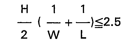
- the physical proportions of the radiant chamber are selected such that: where L is the length of the lower side walls between the end walls (see Figure 2A), H is the height of lower sidewalls, and W is the width of the radiant chamber between the lower side walls.
- L is the length of the lower side walls between the end walls (see Figure 2A)
- H is the height of lower sidewalls
- W is the width of the radiant chamber between the lower side walls.
- a fuel/air mixture is introduced to a plurality of burners 216 proximate floor 202 in the lower portion of the radiant chamber which are disposed to direct combustion gas therefrom upwardly into the chamber in indirect heat exchange relationship with tubular heat exchange means 212 and the process fluid therein.
- no burners are mounted in the end walls 203, lower side walls 204, intermediate side walls 205, and combustion gas outlet means 206 since a large amount of combustion gas introduced to the radiant chamber at locations other than proximate the floor will tend to extend the region of back-mixed gas flow upwardly into the region of desired plug-flow conditions.
- small wall burners may be utilized in the upper portion of the radiant chamber provided that their combustion gas discharge does not appreciably disrupt plug-flow of combustion gas in the upper portion.
- the ratio of heat fluxes between the lower and upper extremities of the cracking tubes proximate respectively roof 209 and floor 202 is from about 3 to about 7.
- the introduction of heat proximate the tube inlets at their lower extremities under back-mixed combustion gas flow conditions in combination with heat absorption proximate the tube outlets at their upper extremities under predominantly plug-flow combustion gas conditions permits control of temperature profile over the tube length while maintaining high thermal efficiency of the furnace.
- FIG. 3 is the same as Figure 2 except that combustion gas outlet means 306 is comprised of upper side wall 308 in addition to end wall extensions 303 (not shown), roof 309, and upper side wall 307 which is opposed and parallel to upper side wall 308.
- This configuration effectively extends the region of combustion gas plug-flow and also results in higher ratio of convective to radiant heat transfer in the upper portion of the radiant chamber.
- reference numbers 401 through 411 and 416 through 418 correspond respectively to Figure 2 reference numbers 201 through 211 and 216 through 218.
- FIG. 4 illustrates an embodiment of the invention having bayonet type tubular heat exchange means 420 which are useful for, among other things, catalytic steam reforming of hydrocarbons ranging from methane through heavy gas oil to produce hydrogen-containing gas, for example, synthesis gas.
- catalytic steam reforming of hydrocarbons ranging from methane through heavy gas oil to produce hydrogen-containing gas, for example, synthesis gas.
- control of temperature profile over the process fluid route within reformer tubes is quite critical.
- the present invention is well suited to meet this requirement.
- Tubular heat exchange devices 420 are comprised of outer tube 421 and one or more inner tubes 422 to form a space for containment of catalyst 423 which is loaded through closure 426. Suitable means (not shown) are employed at the bottom of the catalyst space for catalyst removal.
- Outer tube 421 is fitted with a hydrocarbon feed inlet 424 at the lower extremity thereof and inner tube(s) 422 are in fluid communication with product gas outlet 425 at their lower extremities.
- Upper extremities of inner tubes 422 are in fluid communication with the catalyst space so that process fluid passes upwardly through the catalyst bed in single pass heat exchange relationship with combustion gas in radiant chamber 401 and then downwardly within inner tubes 422 in heat exchange relationship with the upwardly flowing fluid in the catalyst space.
- the bayonet exchange devices 420 extend through radiant chamber 401 and extend downwardly outside the radiant chamber where, in the absence of hot combustion gas, they function as feed/effluent heat exchangers.
Landscapes
- Chemical & Material Sciences (AREA)
- Chemical Kinetics & Catalysis (AREA)
- Organic Chemistry (AREA)
- Engineering & Computer Science (AREA)
- Combustion & Propulsion (AREA)
- Health & Medical Sciences (AREA)
- General Health & Medical Sciences (AREA)
- Inorganic Chemistry (AREA)
- Mechanical Engineering (AREA)
- General Engineering & Computer Science (AREA)
- Production Of Liquid Hydrocarbon Mixture For Refining Petroleum (AREA)
- Heat-Exchange Devices With Radiators And Conduit Assemblies (AREA)
- Organic Low-Molecular-Weight Compounds And Preparation Thereof (AREA)
- Incineration Of Waste (AREA)
Description
- This invention relates to fired, tubular furnaces for heating hydrocarbons. More specifically, the invention relates to a process and apparatus for heating hydrocarbons in furnaces employing vertical tubes wherein combustion gas is passed upwardly through the radiant chamber of the heater or furnace.
- Vertical tube, fired heaters are well known in the petroleum and chemical process industries and are utilized to heat hydrocarbon feed streams in a variety of processes such as distillation, thermal cracking, visbreaking, and, of particular interest here, steam cracking and steam reforming (cf. for example GB-A-974 178, DE-B-1 601 235).
- Heater design is governed by the objectives of the particular process as well as the general objective of high furnace efficiency, that is, the amount of heat absorbed by the process fluid divided by the heating value of fuel input to furnace. For a general discussion of process furnace design, see Perry and Chilton, "Chemical Engineers Handbook", Fifth Edition, McGraw-Hill Book Company, pp. 9-34 to 9-38.
- Usually, a particular process will require a specific fluid temperature at the furnace tube outlet as well as a defined fluid temperature profile along the length of the tube. Steam reforming and steam cracking furnaces typify this circumstance.
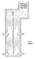
- In, for example, a steam cracking furnace which employs a double-fired, single row, vertical, serpentine, tube coil in a conventional radiant chamber (see Figure 1), a very high, uniform heat flux from combustion gas to process fluid is utilized to bring the fluid quickly to a cracking temperature in the range of from about 815°C to about 925°C. The high, uniform heat flux requirement is normally achieved through use of back-mixed combustion gas conditions throughout the radiant chamber, that is, approximating a well-stirred reactor. In turn, the back-mixed combustion gas condition is brought about by turbulent heat input from a plurality of burners mounted in the radiant chamber enclosure. A conventional arrangement for achieving this is through use of sidewall burners in optional combination with floor burners in a box type radiant chamber wherein combustion gas passes upwardly through the radiant chamber to a convection section.
- Regrettably, the existence of high heat flux throughout the radiant chamber aggravates the known tendency of steam cracking feeds to lay down coke in the tube coil - particularly proximate the coil outlet where process fluid approaches the limit of conversion and has little remaining capacity to absorb heat. In this region, high heat flux causes excessively high tube wall temperatures which result in tube damage and accelerated rates of coke laydown. Furthermore, poor utilization of available heat results in correspondingly poor furnace efficiency.
- Analogous problems are found in other high temperature hydrocarbon heating services. In steam reforming furnaces, for example, tube overheating from utilization of high heat flux throughout the radiant chamber results in catalyst damage with resultant poor feedstock conversion and, ultimately, tube damage.
- It is an object of this invention to control tube wall temperature profile in a fired process heater and gain furnace efficiency that is otherwise lost through use of back-mixed combustion gases throughout the radiant chamber.
- According to the invention, a process and apparatus are provided for heating hydrocarbons by indirect heat exchange with combustion gas in the radiant chamber of a fired tubular heater having a plurality of straight, vertical, tubular heat exchange means in single pass heat exchange relationship with the combustion gas wherein the combustion gas passing over the lower portions of the tubular heat exchange means is predominantly in a back-mixed, i.e. - well-stirred, flow condition and the combustion gas passing over the upper portions thereof is predominantly in a plug-flow condition, i.e. - substantially each gas particle having approximately the same residence time.
- Figure 1 is a cross-sectional view of a commercial prior art process heater employing a vertical serpentine coil and shows the back-mixed combustion gas flow conditions throughout the radiant chamber which result from the burner placement and geometry of the chamber.
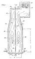
- Figure 2 is a cross-sectional view of a process heater of the invention which employs single pass vertical tubes in combination with burner placement and radiant chamber geometry that result in back-mixed gas flow conditions in the lower portion of the radiant chamber and plug-flow conditions in the upper portion thereof.
- Figure 2A is a side view of Figure 2 and illustrates single pass, vertical tubes.
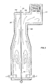
- Figure 3 is the same as Figure 2 except that the upper portion of the radiant chamber has two, parallel, opposed, upper side walls.
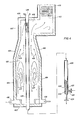
- Figure 4 is a cross-sectional view of another process heater of the invention which employs bayonet type tubular heat exchange means, i.e. - two concentric tubes, having only a single pass in heat exchange relationship with the combustion gas but two passes on the process fluid side. As in Figures 2 and 3, the burner placement and radiant chamber configuration result in predominantly back-mixed gas flow conditions in the lower portion of the radiant chamber and predominantly plug-flow conditions in the upper portion thereof.
- Referring now to Figure 2, there is shown a fired, tubular, process heater which is particularly useful for steam pyrolysis of hydrocarbon feedstocks including ethane, propane, naphtha and light through heavy gas oils to produce lower olefins and co-products.
Radiant chamber 201 is formed byhorizontal floor 202, opposed vertical end walls 203 (see Figure 2A) contiguous with the floor, opposed verticallower side walls 204 that are contiguous with thefloor 202 andend walls 203, opposedintermediate side walls 205 contiguous withend walls 203 andlower side walls 204 and which slope inwardly at an angle from about 10 to about 30 degrees, preferably from about 10 to about 20 degrees, from a plane projected by upward extension of the lower side walls. The upper portion ofradiant chamber 201 has combustion gas outlet means 206 which is contiguous withend walls 203 andintermediate side walls 205. In Figure 2, the combustion gas outlet means 206 is formed by an extension ofend walls 203, a singleupper side wall 207, androof 209. The combustion gas outlet means 206 is a passageway constructed in form suitable for directing combustion gas acrossconvection coils 210 located inconvection chamber 211 where relatively low level heat is recovered from the flue gas. In Figure 2, this passageway is an opening of rectangular cross- section. - The
radiant chamber 201, encloses a plurality of straight, vertical, tubular heat exchange means 212 which are disposed centrally withinradiant chamber 201 parallel to thelower side walls 204, extending throughfloor 202 androof 209, and terminating at their upper extremity proximate combustion gas outlet means 206. In Figure 2; the tubular heat exchange devices are single tubes having a single pass on the process fluid side as well as on the combustion gas side. In steam pyrolysis applications, these tubes are preferably from about 1.8 to about 5.1 cm inside diameter which is suitable for high severity cracking in very short residence times. Regardless of the service, hydrocarbon feedstock is introduced to lower extremities of the tubesproximate floor 202 viatube inlets 213 which, in turn, are fed frominlet manifold 214 via inlet pigtails (not shown). Depending upon the particular service,tube inlets 213 andinlet manifold 214 may be located withinradiant chamber 201. Process fluid is heated in its upward passage through the tubes and discharged at their upper extremities viatube outlets 215 proximate combustion gas outlet means 206. In many services, heated process fluid is collected in an outlet manifold similar toinlet manifold 214. In steam pyrolysis service,tube outlets 215 are closely coupled to cracked gas quench devices which may utilize direct or indirect cooling. Preferably, from one to four tube outlets discharge into a single quench exchanger. Without departing from the scope of the invention,tubes 212 may be branched withinradiant chamber 201. For example two tubes may be joined at one third the height of the radiant chamber and then joined with another pair of tubes at two thirds the height of the radiant chamber with the result of one tube outlet for every four tube inlets. - The heater is so configured that hot combustion gas proximate to and passing over the lower portions of tubular heat exchange means 212 is in a predominantly back-mixed
flow condition 217 and is at a substantially uniform temperature. As the combustion gas passes upwardly through the radiant chamber,intermediate side walls 205 channel the gas into predominantly plug-flow condition 218 proximate the upper portions of tubular heat exchange means 212 as it passes over them and the combustion gas decreases in temperature as it passes upwardly. - Preferably, the physical proportions of the radiant chamber are selected such that:

- A fuel/air mixture is introduced to a plurality of
burners 216proximate floor 202 in the lower portion of the radiant chamber which are disposed to direct combustion gas therefrom upwardly into the chamber in indirect heat exchange relationship with tubular heat exchange means 212 and the process fluid therein. Preferably, no burners are mounted in theend walls 203,lower side walls 204,intermediate side walls 205, and combustion gas outlet means 206 since a large amount of combustion gas introduced to the radiant chamber at locations other than proximate the floor will tend to extend the region of back-mixed gas flow upwardly into the region of desired plug-flow conditions. Despite this preference, small wall burners may be utilized in the upper portion of the radiant chamber provided that their combustion gas discharge does not appreciably disrupt plug-flow of combustion gas in the upper portion. - In operation of the heater of Figure 2 as a steam cracking furnace for the selective production of ethylene from hydrocarbons, back-mixed flow of hot combustion gas at the lower portions of
tubes 212 containing relatively cool process fluid results in a uniform radiation pattern and high heat flux of from about 6800 to about 16,000 calories/hr/cm2. These conditions are desired to meet the heat absorption demands of high severity, short residence time cracking. - As noted previously, utilization of high heat flux as process fluid approaches conversion limits results in tube overheating and laydown of coke in the cracking tubes. This problem is substantially overcome by the present invention in that the upper portions of the tubes containing relatively hot process fluid are subjected to lower heat flux in the range of from about 1300 to about 4100 calories/hr/cm2. The lower heat flux is brought about by use of predominantly plug-flow combustion gas conditions in the upper part of the radiant chamber. Since combustion of fuel is substantially complete as gas enters the upper part of the chamber, heat is depleted from the gas as it flows upwardly in plug-flow and heat flux decreases correspondingly.
- In the above-described service, the ratio of heat fluxes between the lower and upper extremities of the cracking tubes proximate respectively
roof 209 andfloor 202 is from about 3 to about 7. - Accordingly, the introduction of heat proximate the tube inlets at their lower extremities under back-mixed combustion gas flow conditions in combination with heat absorption proximate the tube outlets at their upper extremities under predominantly plug-flow combustion gas conditions permits control of temperature profile over the tube length while maintaining high thermal efficiency of the furnace.
- Figure 3 is the same as Figure 2 except that combustion gas outlet means 306 is comprised of
upper side wall 308 in addition to end wall extensions 303 (not shown),roof 309, andupper side wall 307 which is opposed and parallel toupper side wall 308. This configuration effectively extends the region of combustion gas plug-flow and also results in higher ratio of convective to radiant heat transfer in the upper portion of the radiant chamber. - Referring now to Figure 4,
reference numbers 401 through 411 and 416 through 418 correspond respectively to Figure 2reference numbers 201 through 211 and 216 through 218. - Figure 4 illustrates an embodiment of the invention having bayonet type tubular heat exchange means 420 which are useful for, among other things, catalytic steam reforming of hydrocarbons ranging from methane through heavy gas oil to produce hydrogen-containing gas, for example, synthesis gas. As previously noted, control of temperature profile over the process fluid route within reformer tubes is quite critical. The present invention is well suited to meet this requirement.
- Tubular
heat exchange devices 420 are comprised ofouter tube 421 and one or moreinner tubes 422 to form a space for containment ofcatalyst 423 which is loaded throughclosure 426. Suitable means (not shown) are employed at the bottom of the catalyst space for catalyst removal. -
Outer tube 421 is fitted with ahydrocarbon feed inlet 424 at the lower extremity thereof and inner tube(s) 422 are in fluid communication withproduct gas outlet 425 at their lower extremities. Upper extremities ofinner tubes 422 are in fluid communication with the catalyst space so that process fluid passes upwardly through the catalyst bed in single pass heat exchange relationship with combustion gas inradiant chamber 401 and then downwardly withininner tubes 422 in heat exchange relationship with the upwardly flowing fluid in the catalyst space. - The
bayonet exchange devices 420 extend throughradiant chamber 401 and extend downwardly outside the radiant chamber where, in the absence of hot combustion gas, they function as feed/effluent heat exchangers.
Claims (11)
Applications Claiming Priority (2)
| Application Number | Priority Date | Filing Date | Title |
|---|---|---|---|
| US166880 | 1980-07-08 | ||
| US06/166,880 US4324649A (en) | 1980-07-08 | 1980-07-08 | Fired process heater |
Publications (2)
| Publication Number | Publication Date |
|---|---|
| EP0047359A1 EP0047359A1 (en) | 1982-03-17 |
| EP0047359B1 true EP0047359B1 (en) | 1984-03-28 |
Family
ID=22605054
Family Applications (1)
| Application Number | Title | Priority Date | Filing Date |
|---|---|---|---|
| EP81104097A Expired EP0047359B1 (en) | 1980-07-08 | 1981-05-27 | Heating hydrocarbons in a tubular heater |
Country Status (10)
| Country | Link |
|---|---|
| US (1) | US4324649A (en) |
| EP (1) | EP0047359B1 (en) |
| JP (1) | JPS5929632B2 (en) |
| KR (1) | KR850001672B1 (en) |
| AU (1) | AU523784B2 (en) |
| CA (1) | CA1137521A (en) |
| DD (1) | DD200677C4 (en) |
| DE (1) | DE3162862D1 (en) |
| GR (1) | GR76986B (en) |
| YU (2) | YU43770B (en) |
Cited By (1)
| Publication number | Priority date | Publication date | Assignee | Title |
|---|---|---|---|---|
| US10415820B2 (en) | 2015-06-30 | 2019-09-17 | Uop Llc | Process fired heater configuration |
Families Citing this family (20)
| Publication number | Priority date | Publication date | Assignee | Title |
|---|---|---|---|---|
| US4479869A (en) * | 1983-12-14 | 1984-10-30 | The M. W. Kellogg Company | Flexible feed pyrolysis process |
| JPS60194244A (en) * | 1984-03-15 | 1985-10-02 | Natl House Ind Co Ltd | Structure of opening in wall |
| US4762958A (en) * | 1986-06-25 | 1988-08-09 | Naphtachimie S.A. | Process and furnace for the steam cracking of hydrocarbons for the preparation of olefins and diolefins |
| EP0314408B1 (en) * | 1987-10-23 | 1993-11-18 | C F Braun Inc | Reformer with low fired duty per unit of feedstock |
| US4959079A (en) * | 1987-10-23 | 1990-09-25 | Santa Fe Braun Inc. | Steam reforming process with low fired duty |
| JPH02178546A (en) * | 1988-12-28 | 1990-07-11 | Matsushita Electric Ind Co Ltd | Condensation prevention device |
| FR2641543B1 (en) * | 1989-01-12 | 1991-05-03 | Inst Francais Du Petrole | METHOD AND DEVICE FOR VAPOCRACKING A HYDROCARBON HAVING TWO OR MORE CARBON ATOMS IN A CONVECTION TUBULAR REACTIONAL ZONE |
| JPH03293493A (en) * | 1990-04-12 | 1991-12-25 | Fujita Corp | How to prevent condensation on room windows |
| US5283049A (en) * | 1992-06-18 | 1994-02-01 | Quantum Chemical Corporation | Minimizing coking problems in tubular process furnaces |
| DE4327176C1 (en) * | 1993-08-13 | 1995-01-26 | Metallgesellschaft Ag | Tube furnace for the production of gas mixtures containing carbon monoxide |
| US6395251B1 (en) * | 1999-10-18 | 2002-05-28 | Steven R. Cotting | Steam-hydrocarbon reformer and process |
| US6425757B1 (en) * | 2001-06-13 | 2002-07-30 | Abb Lummus Global Inc. | Pyrolysis heater with paired burner zoned firing system |
| RU2202591C1 (en) * | 2002-02-08 | 2003-04-20 | Общество с ограниченной ответственностью "Фирма ЭСКОРТ" | Tubular furnace |
| US6910878B2 (en) * | 2003-06-19 | 2005-06-28 | Praxair Technology, Inc. | Oxy-fuel fired process heaters |
| US20070196502A1 (en) * | 2004-02-13 | 2007-08-23 | The Procter & Gamble Company | Flowable particulates |
| US20080110801A1 (en) * | 2006-11-09 | 2008-05-15 | Leon Yuan | Process For Heating A Hydrocarbon Stream Entering A Reaction Zone With A Heater Convection Section |
| US7740751B2 (en) | 2006-11-09 | 2010-06-22 | Uop Llc | Process for heating a stream for a hydrocarbon conversion process |
| US8128399B1 (en) * | 2008-02-22 | 2012-03-06 | Great Southern Flameless, Llc | Method and apparatus for controlling gas flow patterns inside a heater chamber and equalizing radiant heat flux to a double fired coil |
| FR2932173B1 (en) * | 2008-06-05 | 2010-07-30 | Air Liquide | STEAM REFORMING PROCESS WITH ENHANCED SMOKE FLOW |
| US8282814B2 (en) * | 2009-03-31 | 2012-10-09 | Uop Llc | Fired heater for a hydrocarbon conversion process |
Family Cites Families (10)
| Publication number | Priority date | Publication date | Assignee | Title |
|---|---|---|---|---|
| US2342011A (en) * | 1941-04-10 | 1944-02-15 | Kellogg M W Co | Furnace for heating fluids |
| US2625918A (en) * | 1949-01-19 | 1953-01-20 | Thomas M Lumly | Fluid heating apparatus |
| US2625916A (en) * | 1950-11-16 | 1953-01-20 | Universal Oil Prod Co | Modified up-draft type of heaters |
| US2721735A (en) * | 1951-10-23 | 1955-10-25 | Shell Dev | Tubular heater with partial flue gas recirculation and heating method |
| US2825313A (en) * | 1955-01-10 | 1958-03-04 | Born Engineering Company | Heaters |
| US3181508A (en) * | 1961-06-26 | 1965-05-04 | Shell Oil Co | Industrial furnaces |
| US3182638A (en) * | 1963-02-19 | 1965-05-11 | Foster Wheeler Corp | Fired heater |
| US3385269A (en) * | 1967-01-26 | 1968-05-28 | Selas Corp Of America | Tube heating furnace |
| US3656913A (en) * | 1970-01-27 | 1972-04-18 | Selas Corp Of America | Catalytic reactor |
| US3671198A (en) * | 1970-06-15 | 1972-06-20 | Pullman Inc | Cracking furnace having thin straight single pass reaction tubes |
-
1980
- 1980-07-08 US US06/166,880 patent/US4324649A/en not_active Expired - Lifetime
-
1981
- 1981-05-27 EP EP81104097A patent/EP0047359B1/en not_active Expired
- 1981-05-27 AU AU71068/81A patent/AU523784B2/en not_active Ceased
- 1981-05-27 DE DE8181104097T patent/DE3162862D1/en not_active Expired
- 1981-06-12 GR GR65232A patent/GR76986B/el unknown
- 1981-06-22 CA CA000380294A patent/CA1137521A/en not_active Expired
- 1981-06-26 YU YU1604/81A patent/YU43770B/en unknown
- 1981-07-07 JP JP56106169A patent/JPS5929632B2/en not_active Expired
- 1981-07-07 KR KR1019810002456A patent/KR850001672B1/en not_active Expired
- 1981-07-07 DD DD81231530A patent/DD200677C4/en unknown
-
1983
- 1983-04-15 YU YU859/83A patent/YU43167B/en unknown
Cited By (1)
| Publication number | Priority date | Publication date | Assignee | Title |
|---|---|---|---|---|
| US10415820B2 (en) | 2015-06-30 | 2019-09-17 | Uop Llc | Process fired heater configuration |
Also Published As
| Publication number | Publication date |
|---|---|
| JPS5785887A (en) | 1982-05-28 |
| EP0047359A1 (en) | 1982-03-17 |
| GR76986B (en) | 1984-09-04 |
| US4324649A (en) | 1982-04-13 |
| DD200677A5 (en) | 1983-06-01 |
| YU43770B (en) | 1989-12-31 |
| DD200677C4 (en) | 1987-09-23 |
| JPS5929632B2 (en) | 1984-07-21 |
| YU85983A (en) | 1983-12-31 |
| KR850001672B1 (en) | 1985-11-13 |
| AU523784B2 (en) | 1982-08-12 |
| YU43167B (en) | 1989-04-30 |
| DE3162862D1 (en) | 1984-05-03 |
| CA1137521A (en) | 1982-12-14 |
| AU7106881A (en) | 1982-01-14 |
| KR830006622A (en) | 1983-09-28 |
| YU160481A (en) | 1983-09-30 |
Similar Documents
| Publication | Publication Date | Title |
|---|---|---|
| US4324649A (en) | Fired process heater | |
| US4499055A (en) | Furnace having bent/single-pass tubes | |
| US3407789A (en) | Heating apparatus and process | |
| JP4871928B2 (en) | Cracking furnace with more uniform heating | |
| US4412975A (en) | Fired process heater | |
| US20080142411A1 (en) | Cracking Furnace | |
| CA3197268A1 (en) | Electric furnace to produce olefins | |
| US4999089A (en) | Cracking furnace | |
| EP4496870A1 (en) | Electrically heated steam cracking furnace for olefin production | |
| JP5619174B2 (en) | HEAT EXCHANGE DEVICE AND ITS MANUFACTURING METHOD | |
| KR20200029091A (en) | Heater for a hydrocarbon stream | |
| US20160334135A1 (en) | Double fired u-tube fired heater | |
| US11105500B2 (en) | Film temperature optimizer for fired process heaters | |
| JPH0359091A (en) | Apparatus for pyrolysis of hydrocarbon |
Legal Events
| Date | Code | Title | Description |
|---|---|---|---|
| PUAI | Public reference made under article 153(3) epc to a published international application that has entered the european phase |
Free format text: ORIGINAL CODE: 0009012 |
|
| AK | Designated contracting states |
Designated state(s): BE DE FR GB IT NL |
|
| 17P | Request for examination filed |
Effective date: 19820211 |
|
| ITF | It: translation for a ep patent filed | ||
| GRAA | (expected) grant |
Free format text: ORIGINAL CODE: 0009210 |
|
| AK | Designated contracting states |
Designated state(s): BE DE FR GB IT NL |
|
| REF | Corresponds to: |
Ref document number: 3162862 Country of ref document: DE Date of ref document: 19840503 |
|
| ET | Fr: translation filed | ||
| PLBE | No opposition filed within time limit |
Free format text: ORIGINAL CODE: 0009261 |
|
| STAA | Information on the status of an ep patent application or granted ep patent |
Free format text: STATUS: NO OPPOSITION FILED WITHIN TIME LIMIT |
|
| 26N | No opposition filed | ||
| PGFP | Annual fee paid to national office [announced via postgrant information from national office to epo] |
Ref country code: NL Payment date: 19900531 Year of fee payment: 10 |
|
| PGFP | Annual fee paid to national office [announced via postgrant information from national office to epo] |
Ref country code: GB Payment date: 19910524 Year of fee payment: 11 |
|
| ITTA | It: last paid annual fee | ||
| PG25 | Lapsed in a contracting state [announced via postgrant information from national office to epo] |
Ref country code: NL Effective date: 19911201 |
|
| NLV4 | Nl: lapsed or anulled due to non-payment of the annual fee | ||
| PG25 | Lapsed in a contracting state [announced via postgrant information from national office to epo] |
Ref country code: GB Effective date: 19920527 |
|
| GBPC | Gb: european patent ceased through non-payment of renewal fee |
Effective date: 19920527 |
|
| PGFP | Annual fee paid to national office [announced via postgrant information from national office to epo] |
Ref country code: FR Payment date: 19950412 Year of fee payment: 15 |
|
| PGFP | Annual fee paid to national office [announced via postgrant information from national office to epo] |
Ref country code: DE Payment date: 19960418 Year of fee payment: 16 |
|
| PG25 | Lapsed in a contracting state [announced via postgrant information from national office to epo] |
Ref country code: FR Effective date: 19970131 |
|
| REG | Reference to a national code |
Ref country code: FR Ref legal event code: ST |
|
| PGFP | Annual fee paid to national office [announced via postgrant information from national office to epo] |
Ref country code: BE Payment date: 19970606 Year of fee payment: 17 |
|
| PG25 | Lapsed in a contracting state [announced via postgrant information from national office to epo] |
Ref country code: DE Free format text: LAPSE BECAUSE OF NON-PAYMENT OF DUE FEES Effective date: 19980203 |
|
| PG25 | Lapsed in a contracting state [announced via postgrant information from national office to epo] |
Ref country code: BE Free format text: LAPSE BECAUSE OF NON-PAYMENT OF DUE FEES Effective date: 19980531 |
|
| BERE | Be: lapsed |
Owner name: THE M.W. KELLOGG CY Effective date: 19980531 |