EP0047065B1 - Distributed phase rf coil - Google Patents
Distributed phase rf coil Download PDFInfo
- Publication number
- EP0047065B1 EP0047065B1 EP81303522A EP81303522A EP0047065B1 EP 0047065 B1 EP0047065 B1 EP 0047065B1 EP 81303522 A EP81303522 A EP 81303522A EP 81303522 A EP81303522 A EP 81303522A EP 0047065 B1 EP0047065 B1 EP 0047065B1
- Authority
- EP
- European Patent Office
- Prior art keywords
- segments
- sample
- coil
- coil arrangement
- loop
- Prior art date
- Legal status (The legal status is an assumption and is not a legal conclusion. Google has not performed a legal analysis and makes no representation as to the accuracy of the status listed.)
- Expired
Links
- 238000005481 NMR spectroscopy Methods 0.000 claims description 75
- 230000008878 coupling Effects 0.000 claims description 37
- 238000010168 coupling process Methods 0.000 claims description 37
- 238000005859 coupling reaction Methods 0.000 claims description 37
- 230000003068 static effect Effects 0.000 claims description 14
- 238000006073 displacement reaction Methods 0.000 claims description 6
- 230000000694 effects Effects 0.000 claims description 5
- 230000005684 electric field Effects 0.000 claims description 4
- 230000001747 exhibiting effect Effects 0.000 claims description 2
- 239000012212 insulator Substances 0.000 claims 1
- 239000000523 sample Substances 0.000 description 64
- 239000011521 glass Substances 0.000 description 15
- 229910001369 Brass Inorganic materials 0.000 description 11
- 239000010951 brass Substances 0.000 description 11
- 239000004020 conductor Substances 0.000 description 11
- 239000011888 foil Substances 0.000 description 10
- 230000005540 biological transmission Effects 0.000 description 8
- 238000003384 imaging method Methods 0.000 description 6
- 230000001965 increasing effect Effects 0.000 description 4
- 230000001934 delay Effects 0.000 description 3
- 238000001514 detection method Methods 0.000 description 3
- 230000001678 irradiating effect Effects 0.000 description 3
- 230000005415 magnetization Effects 0.000 description 3
- 230000010363 phase shift Effects 0.000 description 3
- 238000004458 analytical method Methods 0.000 description 2
- 239000003990 capacitor Substances 0.000 description 2
- 230000007423 decrease Effects 0.000 description 2
- 230000009977 dual effect Effects 0.000 description 2
- 230000005284 excitation Effects 0.000 description 2
- 230000035945 sensitivity Effects 0.000 description 2
- RYGMFSIKBFXOCR-UHFFFAOYSA-N Copper Chemical compound [Cu] RYGMFSIKBFXOCR-UHFFFAOYSA-N 0.000 description 1
- 238000010521 absorption reaction Methods 0.000 description 1
- 210000000481 breast Anatomy 0.000 description 1
- 239000010949 copper Substances 0.000 description 1
- 229910052802 copper Inorganic materials 0.000 description 1
- 230000003247 decreasing effect Effects 0.000 description 1
- 238000010586 diagram Methods 0.000 description 1
- 230000003292 diminished effect Effects 0.000 description 1
- 230000005672 electromagnetic field Effects 0.000 description 1
- 230000004907 flux Effects 0.000 description 1
- 230000006698 induction Effects 0.000 description 1
- 230000001939 inductive effect Effects 0.000 description 1
- 230000001902 propagating effect Effects 0.000 description 1
- 238000000926 separation method Methods 0.000 description 1
- 238000004804 winding Methods 0.000 description 1
Images


Classifications
-
- G—PHYSICS
- G01—MEASURING; TESTING
- G01R—MEASURING ELECTRIC VARIABLES; MEASURING MAGNETIC VARIABLES
- G01R33/00—Arrangements or instruments for measuring magnetic variables
- G01R33/20—Arrangements or instruments for measuring magnetic variables involving magnetic resonance
- G01R33/28—Details of apparatus provided for in groups G01R33/44 - G01R33/64
- G01R33/42—Screening
- G01R33/422—Screening of the radio frequency field
-
- G—PHYSICS
- G01—MEASURING; TESTING
- G01R—MEASURING ELECTRIC VARIABLES; MEASURING MAGNETIC VARIABLES
- G01R33/00—Arrangements or instruments for measuring magnetic variables
- G01R33/20—Arrangements or instruments for measuring magnetic variables involving magnetic resonance
- G01R33/28—Details of apparatus provided for in groups G01R33/44 - G01R33/64
- G01R33/32—Excitation or detection systems, e.g. using radio frequency signals
- G01R33/36—Electrical details, e.g. matching or coupling of the coil to the receiver
- G01R33/3628—Tuning/matching of the transmit/receive coil
Definitions
- This invention relates to nuclear magnetic resonance (NMR), and in particular, to RF coil designs particularly well suited for NMR imaging.
- the RF coil provides the dual function of a transmitting or exciting coil for applying an RF magnetic field to a sample under NMR analysis and of a receiving coil for detecting the radio frequency magnetization of the sample.
- NMR spectrometers In recent years, advances in the art of superconducting magnets have permitted NMR spectrometers to be built which operate at frequencies as high as 600 megahertz. At such frequencies, the performance of the RF coil in the spectrometer becomes a major limiting factor in the overall system performance.
- the RF coil which surrounds the sample under analysis, has the function of magnetically coupling the spectrometer to the sample.
- An example of a prior art RF coil circuit for a nuclear magnetic resonance probe having a tuning range of 6 to 32 megahertz is disclosed in U.S. Patent No. 4,095,168.
- the NMR signal improves as the strength of the static magnetic field and the operating frequency are increased.
- the phenomenon which limits the useful operating frequency is the RF absorption effects in the sample.
- the frequency and coil size at which this limit is approached is such that conventional RF coils suffer from all of the problems discussed above.
- the efficiency and uniformity of the coupling between the sample and spectrometer have a significant effect on the quality of the resultant image.
- the propagation delay inherent in the coil conductor, is incorporated into the design of the coil rather than being treated as a limiting phenomenon.
- the delays are calculated and used to put the correct current in the correct place.
- the electrical phase of the current at each segment of wire which contributes to the magnetic field is in the correct position, due to the geometry of the coil and the distribution of the electrical delays, to produce the desired magnetic field.
- the result can be considered part RF coil and part resonant transmission line.
- the invention provides a distributed phase RF coil arrangement for exciting a sample under NMR analysis with an oscillating magnetic field such as an RF field and/or for detecting nuclear magnetic resonance of the sample, and adapted for a relatively high degree of magnetic coupling with the sample, said arrangement comprising:
- the invention provides a distributed phase RF coil arrangement for exciting a sample under NMR analysis in a static magnetic field with an oscillating magnetic field such as an RF field and/or for detecting nuclear magnetic resonance of said sample, and adapted for a relatively high level of magnetic coupling with said sample, which comprises:-
- the invention provides a distributed phase RF coil arrangement for exciting a sample under NMR analysis in a static magnetic field with an oscillating magnetic field such as an RF field and/or for detecting nuclear magnetic resonance of said sample, and adapted for a relatively high level of magnetic coupling with said sample, which comprises:-
- the invention provides a distributed phase RF coil arrangement for exciting a sample under NMR analysis in a static magnetic field with an oscillating magnetic field such as an RF field and/or for detecting nuclear magnetic resonance of said sample, and adapted for a relatively high level of magnetic coupling with said sample, which comprises:
- This novel design has the advantages of providing both a uniform irradiating field when used as a transmitting coil and a uniform sensitivity when used as a receiving coil. In imaging applications, this results in a superior image and increased efficiency by permitting the coil to be placed closer to the sample.
- This novel design has many more "turns" than the traditional coil for the same frequency and size, a feature made possible by energizing the coil with a standing wave at the frequency of interest.
- RF coils for NMR apparatus were restricted by wavelength considerations, which dictated that their length be no greater than IJ20 at the frequency of interest.
- the total length of all shielded and unshielded segments is approximately equal to A at the frequency of interest, as adjusted to account for inductive effects between the unshielded segments.
- the unshielded segments can be oriented substantially parallel to the axis of the cylindrical coil support.
- the unshielded segments are interconnected by shielded segments to form the continuous electrically conductive loop.
- the unshielded segments are slightly angled relative to the axis of the coil support at an angle proportional to their angular displacement along the periphery of the NMR sample region.
- RF coils were conventionally disposed with unshielded wires wound cylindrically around the coil support, as shown in Fig. 5 of DE-A-2 942 020.
- this document also discloses an NMR RF coil arrangement comprising means for electrostatically decoupling the sample.
- the large number of turns increases the efficiency of the coil.
- the RF coil arrangement 10 includes a coil support or coil former 12 which, in one model of the invention, is a 82.55 mm (3-1/4 inch) diameter, 228.6 mm (9 inch) long, insulating tube made of glass and open at both ends. At either end of the glass tube 12 there is provided a 76.20 mm (3 inch) wide strip of thin brass foil 14 which is soldered end to end along line 16 to form a tight fit around the glass tube 12.
- the sample that is to undergo analysis is inserted through one end of the glass tube 12, generally in the central region thereof.
- the two brass foil strips 14 provide an RF shield at each end of the glass tube 12 thereby defining an active portion 18 in the central region of the glass tube 12.
- the plurality of wires 20 are wound around the glass tube 12.
- the plurality of wires 20 is preferably copper or other conductive material and soldered by cross wire 22 to form closed loops.
- the closed loops of wires 20 are spaced at about 3.17 mm (1/ 8 inch) intervals over the 76.20 mm (3 inch) portion of the glass tube within the two brass foil strips 14.
- Each end of the cross wire 22 is soldered to one of the brass foil strips 14 and also has a discontinuity 24 therebetween.
- the plurality of wires 20 together with cross wire 22 forms a "Faraday shield" for electrostatically decoupling a sample within the active portion 18 of the NMR sample region from electric fields of the coil arrangement 10 and for shielding the coil from electrostatic atmospheric noise.
- the Faraday shield permits the magnetic field to pass through to the sample under NMR analysis. This electric decoupling reduces the RF energy applied to the sample since .the energy applied is related to the product of the electric and magnetic fields.
- the shield also decreases the effect of the sample on the tune of the RF coil arrangement 10. This is crucial since, for example, a slightly conductive sample can increase the distributed capacitance of a coil arrangement and thereby shift its resonant frequency.
- the Faraday shield together with brass foil strips 14 form a shield between the sample under NMR analysis and the RF coil arrangement 10. This shield does not shield the NMR sample from the desired component of the magnetic field which is the portion normal to the axis of the glass tube 12.
- the coil arrangement 10 further includes a closed conductive loop 26 preferably disposed about said glass tube having the general configuration of a toroid.
- conductive loop 26 is shown in Fig. 3 as it would look if removed from glass tube 12 and laid out flat.
- the conductive loop 26 includes shielded coaxial cable segments 28 and unshielded wire segments 30.
- the unshielded segments 30 comprise the active wires while the shielded coaxial cables 28 form the return or inactive wire portions.
- Both ends of the shield of each shielded segment 28 are soldered to brass foil strips 14 at contact points 32.
- the discontinuity 24 in the cross wire 22 ensures that there is no shorted conducting path parallel to the active wires and between them and the sample. Any such shorted conducting path would tend to reduce the magnetic coupling between the active wires and the sample.
- the shielded segments of the wire are lifted up and away from the glass tube 12 to a distance approximately 31.75 mm (1-1/4 inches) therefrom.
- the shielded segments 28 are 4.76 mm (3/16 inch) outer diameter rigid coaxial cable.
- Each segment of the shielded wire is approximately 152.4 mm (6 inches) long.
- the active wire segments 30 are roughly 76.2 mm (3 inches) long and extend across the closed loop wires 20.
- the resonant frequency of this example is about 60 megahertz.
- Current propagating along active wires 30 produces a magnetic field in the sample.
- the resonant magnetic field of the sample produces a current in the active wire segments 30.
- the active wire segments 30 are arranged in generally axial relation with the glass tube 12 to produce lines of flux orthogonal to said axis.
- the active wires 30 are in parallel relation to each other and are slightly angled relative to the axis of tube 12.
- phase delay between adjacent pairs of active segments 30 of the conductive loop 26 is generally equal to the angular displacement between said pair of active segments thereby generating a magnetic field having a relatively substantial normal component throughout the active portion 18 of said NMR sample region.
- the RF coil arrangement 10 is connected to a spectrometer (not shown) by conductor 34 which is a coaxial cable.
- the shielded segment 36 of conductor 34 is soldered to the brass foil 14. A portion of the shielding is removed to create active segment 37 of conductor 34 and to permit the active segment 37 to inductively couple to the RF coil arrangement 10.
- the end of active segment 37 of conductor 34 is soldered to the brass foil 14 at point 38.
- the active segment 37 is positioned to provide the desired coupling. Preferably, this is accomplished by placing active segment 37 adjacent to one of the active segments 30 of conductive loop 26.
- the orientation of active segment 37 of conductor 34 affects the coupling achieved so that, together with the conductor 34 and variable capacitor 80 (shown in Fig. 5) the impedance at 81 can be set to 50 ohms to permit impedance matching.
- Other modes of coupling to the resonant RF coil arrangement can be made.
- One example is to couple at two points 90 degrees apart.
- the nuclear spins of the NMR sample are sensitive only to a rotating magnetic field, or to a circularly polarized magnetic field.
- the field generated is circularly polarized and is, as a result, more effective.
- the resultant field is twice as strong.
- the detecting mode since the NMR magnetization of the sample is circularly polarized, the detection efficiency is thereby improved.
- an additional thin brass cylindrical shield 42 is wrapped around the outside of return shielded wire segments 28 and is soldered to brass foil strips 14.
- the conductive loop 26 described in connection with the preferred embodiment discussed hereinabove consists of eight active segments 30 and eight return segments 28. Other arrangements are contemplated, however, wherein the number of either active or return segments is some other number. In addition, there may be more than one conductive loop 26.
- the coupling between the conductive loop 26 and an NMR analysis system as shown in part in Fig. 4 is provided by a conductor 34 which has shielded segment 36 and active segment 37 connected to the RF coil arrangement at connection 38. Adding another conductive loop 26A (a portion of which is shown in Fig. 3) to the RF coil arrangement 10 further increases the uniformity of the RF field and increases the efficiency of the magnetic coupling to the sample by providing more "turns" of the conductive loop.
- the second conductive loop 26A essentially identical to conductive loop 26, is assembled about glass tube 12, but offset therefrom by one-half turn spacing.
- one of the conductive loops can be considered a driven conductive loop while the other one undriven. Coupling between the unshielded or active wires 30 of the driven loop induces current in the undriven loop such that both loops 26 and 26A contribute to the RF field that is coupled to the sample. Conversely, the NMR signal is coupled to both conductive loops 26 and 26A and transmitted to an NMR analysis system.
- the RF coil arrangement 10 has a resonant frequency determined by its dimensions and in particular by the total length of the shielded and unshielded wire segments of conductive loop 26.
- Fig. 6 which consists of two transmission lines 61 and,62.
- the signal in the upper line 61 will meet the signal from the lower line 62 at point B with exactly the same amplitude.
- Point B will appear as an open circuit for signals on each line.
- a reflection of the current in each line will occur and will propagate back to point A.
- the total path travelled by the signal is ⁇ , i.e., a 360 degree phase shift.
- the impedance at point A then will also appear nearly as an open circuit and a standing wave will occur on the lines 61 and 62 such that relative voltage maxima occur at points A and B and current maxima at points C and C'.
- the voltage and current wave forms are graphically presented at Fig. 7.
- Fig. 8 results, which is seen to be the configuration of Figs. 1-3. Points A and B are on opposite sides of the coil, as are points C and C' as shown in Fig. 8.
- the number of turns and the length of the shielded wires can be varied within that limit. Because the field from one unshielded wire is coupled to the adjacent unshielded wires an increase in effective inductance occurs and the frequency of resonance is reduced. The amount of induction is related to the number of turns and the relative lengths of the unshielded wire.
- the current in each successive segment is shifted by an amount equal to its angular rotation. (See Fig. 9.)
- the transmission line is formed as shown in Fig. 10 then the current in segment XX as shown in Fig. 11 is shifted from segment YY by 180° + 8°.
- its position on the former is shifted by 180° + 8° as shown in Fig. 11 and the same conditions for a uniform RF field are established as in Fig. 8.
- Coupling is as in a transformer and the high impedance of the coil is lowered by the square root of the turns ratio to values suitable for low impedance transmission lines. Matching can be done either at the coit or at some other point such as the signal separation point 40.
- the RF coil arrangement 10 is shown as it interrelates with other components of the system.
- the system includes a magnet 50 which is powered by a magnet power supply 52.
- an RF pulse gate 54 for gating radio frequency electrical signals.
- the radio frequency signals are amplified by a radio frequency power amplifier 58.
- a coupling network 40 couples the radio frequency excitation signals with the RF coil arrangement 10.
- detection is accomplished by the combination of the RF coil arrangement 10 in its detecting mode, the coupling network 40 and a low noise amplifier 60.
- the coupling network 40 during detection serves to separate the detected signals from the excitation signals, and the low noise amplifier 60 for amplifying the detected NMR signals.
- Fig. 5 shows an example of a coupling network 40.
- Variable capacitor 80 permits adjustment of the RF coil impedance to a value of 50 ohms for proper operation with commercially available RF power amplifier 58 and low noise amplifier 60.
Landscapes
- Physics & Mathematics (AREA)
- Health & Medical Sciences (AREA)
- Epidemiology (AREA)
- Condensed Matter Physics & Semiconductors (AREA)
- General Physics & Mathematics (AREA)
- Magnetic Resonance Imaging Apparatus (AREA)
Description
- This invention relates to nuclear magnetic resonance (NMR), and in particular, to RF coil designs particularly well suited for NMR imaging. The RF coil provides the dual function of a transmitting or exciting coil for applying an RF magnetic field to a sample under NMR analysis and of a receiving coil for detecting the radio frequency magnetization of the sample.
- In recent years, advances in the art of superconducting magnets have permitted NMR spectrometers to be built which operate at frequencies as high as 600 megahertz. At such frequencies, the performance of the RF coil in the spectrometer becomes a major limiting factor in the overall system performance. The RF coil, which surrounds the sample under analysis, has the function of magnetically coupling the spectrometer to the sample. An example of a prior art RF coil circuit for a nuclear magnetic resonance probe having a tuning range of 6 to 32 megahertz is disclosed in U.S. Patent No. 4,095,168.
- At high frequencies, the distributed capacitance of such coils becomes significant so that even a single turn coil becomes "self-resonant". When this limit is approached, the homogeneity of the RF field decreases, due to the phase shift in different parts of the coil. Moreover, as the number of turns of the coil is reduced, the homogeneity as well as efficiency of the coil, both in generating fields and in picking up the signal, is diminished.
- A further problem occurring in high frequency superconducting magnets is that the static magnetic field is co-axial with the axis of the cylindrical bore of the magnet. Since the RF field must be perpendicular, i.e., normal, to this axis, the conventional coil design is to place one loop on each side of the cylindrical sample. This inherently inefficient configuration, and variations of it, is the current state of the art in NMR spectrometers.
- In the separate but related field of NMR imaging, the sample sizes, frequencies, and magnet geometry are such that exactly the same problems occur. Again, the same general coil designs are the state of the art. In NMR imaging, the homogeneity of the irradiating field and the uniformity of the sensitivity to the signal are even more important than in conventional NMR spectroscopy. Typically, homogeneity can be improved by increasing the diameter of the RF coil and moving it away from the sample. This approach, however, is inherently inefficient and results in decreased magnetic coupling of the coil with the sample.
- Typically, the NMR signal improves as the strength of the static magnetic field and the operating frequency are increased. In NMR imaging, the phenomenon which limits the useful operating frequency is the RF absorption effects in the sample. With medical applications, the frequency and coil size at which this limit is approached is such that conventional RF coils suffer from all of the problems discussed above. At any field strength, the efficiency and uniformity of the coupling between the sample and spectrometer have a significant effect on the quality of the resultant image.
- We have discovered an RF coil arrangement which generally overcomes the problems noted above; principally, by recognizing the phase shift or propagation delay inherent in an RF coil conductor and incorporating this phenomenon into the design in such manner that the delay at each increment of the loop is predetermined and contributes to a high level of magnetic coupling with the sample.
- Thus, the propagation delay, inherent in the coil conductor, is incorporated into the design of the coil rather than being treated as a limiting phenomenon. The delays are calculated and used to put the correct current in the correct place. In other words, the electrical phase of the current at each segment of wire which contributes to the magnetic field is in the correct position, due to the geometry of the coil and the distribution of the electrical delays, to produce the desired magnetic field. The result can be considered part RF coil and part resonant transmission line.
- In one aspect the invention provides a distributed phase RF coil arrangement for exciting a sample under NMR analysis with an oscillating magnetic field such as an RF field and/or for detecting nuclear magnetic resonance of the sample, and adapted for a relatively high degree of magnetic coupling with the sample, said arrangement comprising:
- at least one electrically conductive loop defining an NMR sample region therewithin, said loop having alternating shielded and unshielded segments of predetermined lengths, said shielded segments defining inactive portions of said conductive loop, and
- connecting pairs of unshielded segments, said unshielded segments defining active portions of the conductive loop for magnetically coupling with the sample, said unshielded segments being adapted for current propagation along each of said active portions such that the propagation delay between points on said active portions is proportional to the angular displacement along the periphery of the NMR sample region between said points of said active portions.
- In a second aspect the invention provides a distributed phase RF coil arrangement for exciting a sample under NMR analysis in a static magnetic field with an oscillating magnetic field such as an RF field and/or for detecting nuclear magnetic resonance of said sample, and adapted for a relatively high level of magnetic coupling with said sample, which comprises:-
- a) a coil support defining an NMR sample region therewithin;
- b) electrically conductive means for shielding a portion of the NMR sample region from RF irradiation, said shielded portion of the NMR sample region defining therewithin a first inactive portion and thereby delimiting the non-shielded active portion of the sample region;
- c) means electrically connected to said shielding means for decoupling a sample within the active portion of the NMR sample region from electric fields of the coil generated by an RF magnetic field and for shielding said sample from axial components of said RF magnetic field and from electrostatic atmospheric noise; and
- d) an electrically conductive loop peripherally disposed about said coil support having alternating shielded and unshielded segments for magnetically coupling components of said RF field which are normal to said static field with said sample wherein:
- i) said shielded segments define inactive regions of said conductive loop and connect pairs of unshielded segments; and
- ii) said unshielded segments define active regions of said conductive loop, said unshielded segments being disposed about the active portion of the NMR sample region in generally axial relation with said coil support being adapted for current propagation along each of said active region segments such that the phase delay between adjacent pairs of active segments of said coil is proportional to the angular displacement between said pair of active segments, thereby generating a magnetic field having a relatively substantial normal component throughout the active portion of said NMR sample region.
- In a third aspect the invention provides a distributed phase RF coil arrangement for exciting a sample under NMR analysis in a static magnetic field with an oscillating magnetic field such as an RF field and/or for detecting nuclear magnetic resonance of said sample, and adapted for a relatively high level of magnetic coupling with said sample, which comprises:-
- a coil support defining an NMR sample region therewithin; and
- an electrically conductive loop comprised of a plurality of active segments and disposed about said coil support for magnetically coupling components of said RF field which are normal to said static field with said sample, said loop, when energized, exhibiting a standing wave.
- In a fourth aspect the invention provides a distributed phase RF coil arrangement for exciting a sample under NMR analysis in a static magnetic field with an oscillating magnetic field such as an RF field and/or for detecting nuclear magnetic resonance of said sample, and adapted for a relatively high level of magnetic coupling with said sample, which comprises:
- a generally cylindrical coil support defining an NMR sample region therewithin and having a central longitudinal axis; and
- an electrically conductive loop disposed about said coil support for magnetically coupling components of said RF field which are normal to said static magnetic field with said sample, said loop including a plurality of active segments for establishing or detecting RF signals, which segments are oriented substantially parallel to said longitudinal axis.
- This novel design has the advantages of providing both a uniform irradiating field when used as a transmitting coil and a uniform sensitivity when used as a receiving coil. In imaging applications, this results in a superior image and increased efficiency by permitting the coil to be placed closer to the sample.
- This novel design has many more "turns" than the traditional coil for the same frequency and size, a feature made possible by energizing the coil with a standing wave at the frequency of interest. Conventionally, RF coils for NMR apparatus were restricted by wavelength considerations, which dictated that their length be no greater than IJ20 at the frequency of interest. In the preferred embodiment, the total length of all shielded and unshielded segments is approximately equal to A at the frequency of interest, as adjusted to account for inductive effects between the unshielded segments.
- Furthermore, because of the luxury of a substantial coil length, the unshielded segments can be oriented substantially parallel to the axis of the cylindrical coil support. In the preferred embodiment the unshielded segments are interconnected by shielded segments to form the continuous electrically conductive loop. To account for propagation delays, the unshielded segments are slightly angled relative to the axis of the coil support at an angle proportional to their angular displacement along the periphery of the NMR sample region. In the prior art, RF coils were conventionally disposed with unshielded wires wound cylindrically around the coil support, as shown in Fig. 5 of DE-A-2 942 020. However, this document also discloses an NMR RF coil arrangement comprising means for electrostatically decoupling the sample.
- In addition to increasing the uniformity as mentioned above, the large number of turns increases the efficiency of the coil. When used as an irradiating coil, this means that the same amount of current produces a higher magnetic field. When used as a receiving coil, this means that the same amount of sample magnetization produces a larger emf.
- Preferred embodiments of the invention will now be described, by way of example, with reference to the accompanying drawings, wherein:-
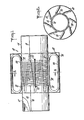
- Fig. 1 is a plan view, partly in section, of a coil arrangement according to the present invention.
- Fig. 2 is a section taken along line 2-2 of Fig. 1.
- Fig. 3 is a development view showing the conductive loop of the coil arrangement of Fig. 1 as it would look if removed from the coil former and laid out flat.
- Fig. 4 is a block diagram of a portion of an NMR system including an RF coil arrangement.
- Fig. 5 is an example in schematic form of a coupling network.
- Fig. 6 is illustrative of a pair of linear transmission lines.
- Fig. 7 is a graph of the waveforms of the transmission lines shown in Fig. 6.
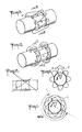
- Fig. 8 is a diagrammatic representation in perspective of the coil arrangement shown in Fig. 1.
- Fig. 9 is an end view of Fig. 8.
- Fig. 10 shows an alternate winding of the conductive loop.
- Fig. 11 is an end view of Fig. 10.
- Referring now to Fig. 1, there is shown a distributed phase RF coil arrangement generally designated as 10 incorporating features of the present invention. The RF coil arrangement 10 includes a coil support or coil former 12 which, in one model of the invention, is a 82.55 mm (3-1/4 inch) diameter, 228.6 mm (9 inch) long, insulating tube made of glass and open at both ends. At either end of the
glass tube 12 there is provided a 76.20 mm (3 inch) wide strip ofthin brass foil 14 which is soldered end to end alongline 16 to form a tight fit around theglass tube 12. - The sample that is to undergo analysis is inserted through one end of the
glass tube 12, generally in the central region thereof. The two brass foil strips 14 provide an RF shield at each end of theglass tube 12 thereby defining an active portion 18 in the central region of theglass tube 12. - Between the two strips of
brass foil 14, a plurality ofwires 20 are wound around theglass tube 12. The plurality ofwires 20 is preferably copper or other conductive material and soldered bycross wire 22 to form closed loops. The closed loops ofwires 20 are spaced at about 3.17 mm (1/ 8 inch) intervals over the 76.20 mm (3 inch) portion of the glass tube within the two brass foil strips 14. Each end of thecross wire 22 is soldered to one of the brass foil strips 14 and also has adiscontinuity 24 therebetween. - The plurality of
wires 20 together withcross wire 22 forms a "Faraday shield" for electrostatically decoupling a sample within the active portion 18 of the NMR sample region from electric fields of the coil arrangement 10 and for shielding the coil from electrostatic atmospheric noise. Moreover, the Faraday shield permits the magnetic field to pass through to the sample under NMR analysis. This electric decoupling reduces the RF energy applied to the sample since .the energy applied is related to the product of the electric and magnetic fields. The shield also decreases the effect of the sample on the tune of the RF coil arrangement 10. This is crucial since, for example, a slightly conductive sample can increase the distributed capacitance of a coil arrangement and thereby shift its resonant frequency. The Faraday shield together with brass foil strips 14 form a shield between the sample under NMR analysis and the RF coil arrangement 10. This shield does not shield the NMR sample from the desired component of the magnetic field which is the portion normal to the axis of theglass tube 12. - The coil arrangement 10 further includes a closed
conductive loop 26 preferably disposed about said glass tube having the general configuration of a toroid. For additional clarity,conductive loop 26 is shown in Fig. 3 as it would look if removed fromglass tube 12 and laid out flat. Theconductive loop 26 includes shieldedcoaxial cable segments 28 andunshielded wire segments 30. Theunshielded segments 30 comprise the active wires while the shieldedcoaxial cables 28 form the return or inactive wire portions. - Both ends of the shield of each shielded
segment 28 are soldered to brass foil strips 14 at contact points 32. Thediscontinuity 24 in thecross wire 22 ensures that there is no shorted conducting path parallel to the active wires and between them and the sample. Any such shorted conducting path would tend to reduce the magnetic coupling between the active wires and the sample. In connection with this model of the RF coil arrangement 10, which is approximately 228.6 mm (9 inches) long, the shielded segments of the wire are lifted up and away from theglass tube 12 to a distance approximately 31.75 mm (1-1/4 inches) therefrom. The shieldedsegments 28 are 4.76 mm (3/16 inch) outer diameter rigid coaxial cable. Each segment of the shielded wire is approximately 152.4 mm (6 inches) long. - The
active wire segments 30 are roughly 76.2 mm (3 inches) long and extend across theclosed loop wires 20. The resonant frequency of this example is about 60 megahertz. Current propagating alongactive wires 30 produces a magnetic field in the sample. Similarly, the resonant magnetic field of the sample produces a current in theactive wire segments 30. Theactive wire segments 30 are arranged in generally axial relation with theglass tube 12 to produce lines of flux orthogonal to said axis. Preferably, theactive wires 30 are in parallel relation to each other and are slightly angled relative to the axis oftube 12. The combination of the angle of the active wire segments, together with the distance of each of thereturn wire segments 28, produce the desired effect of overcoming the problem of the phase delay inherent in the distributed capacitance of theconductive loop 26. In other words, the phase delay between adjacent pairs ofactive segments 30 of theconductive loop 26 is generally equal to the angular displacement between said pair of active segments thereby generating a magnetic field having a relatively substantial normal component throughout the active portion 18 of said NMR sample region. - As further shown in Fig. 3, the RF coil arrangement 10 is connected to a spectrometer (not shown) by
conductor 34 which is a coaxial cable. The shieldedsegment 36 ofconductor 34 is soldered to thebrass foil 14. A portion of the shielding is removed to create active segment 37 ofconductor 34 and to permit the active segment 37 to inductively couple to the RF coil arrangement 10. The end of active segment 37 ofconductor 34 is soldered to thebrass foil 14 atpoint 38. The active segment 37 is positioned to provide the desired coupling. Preferably, this is accomplished by placing active segment 37 adjacent to one of theactive segments 30 ofconductive loop 26. The orientation of active segment 37 ofconductor 34 affects the coupling achieved so that, together with theconductor 34 and variable capacitor 80 (shown in Fig. 5) the impedance at 81 can be set to 50 ohms to permit impedance matching. - Other modes of coupling to the resonant RF coil arrangement can be made. One example is to couple at two points 90 degrees apart. The nuclear spins of the NMR sample are sensitive only to a rotating magnetic field, or to a circularly polarized magnetic field. By connecting to the RF coil arrangement's conductive loop at two places and driving the two points with a 90 degree phase difference, the field generated is circularly polarized and is, as a result, more effective. The resultant field is twice as strong. Similarly, during the detecting mode, since the NMR magnetization of the sample is circularly polarized, the detection efficiency is thereby improved.
- For added shielding, such as for example, from outside noise, an additional thin brass
cylindrical shield 42 is wrapped around the outside of return shieldedwire segments 28 and is soldered to brass foil strips 14. - The
conductive loop 26 described in connection with the preferred embodiment discussed hereinabove, consists of eightactive segments 30 and eightreturn segments 28. Other arrangements are contemplated, however, wherein the number of either active or return segments is some other number. In addition, there may be more than oneconductive loop 26. The coupling between theconductive loop 26 and an NMR analysis system as shown in part in Fig. 4 is provided by aconductor 34 which has shieldedsegment 36 and active segment 37 connected to the RF coil arrangement atconnection 38. Adding anotherconductive loop 26A (a portion of which is shown in Fig. 3) to the RF coil arrangement 10 further increases the uniformity of the RF field and increases the efficiency of the magnetic coupling to the sample by providing more "turns" of the conductive loop. The secondconductive loop 26A, essentially identical toconductive loop 26, is assembled aboutglass tube 12, but offset therefrom by one-half turn spacing. In such a dual conductive loop embodiment, one of the conductive loops can be considered a driven conductive loop while the other one undriven. Coupling between the unshielded oractive wires 30 of the driven loop induces current in the undriven loop such that bothloops conductive loops - The RF coil arrangement 10 has a resonant frequency determined by its dimensions and in particular by the total length of the shielded and unshielded wire segments of
conductive loop 26. In considering the operation of the conductive loop refer to Fig. 6 which consists of twotransmission lines upper line 61 will meet the signal from thelower line 62 at point B with exactly the same amplitude. Point B will appear as an open circuit for signals on each line. A reflection of the current in each line will occur and will propagate back to point A. The total path travelled by the signal is λ, i.e., a 360 degree phase shift. The impedance at point A then will also appear nearly as an open circuit and a standing wave will occur on thelines - Now, if this transmission line is wound upon a coil former so that the turns are uniformly distributed and sections of the line are unshielded so as to no longer bound the electromagnetic field between the inner and outer conductors, the configuration of Fig. 8 results, which is seen to be the configuration of Figs. 1-3. Points A and B are on opposite sides of the coil, as are points C and C' as shown in Fig. 8. Thus, it can be seen that as a first approximation, the total length of all segments must approximately equal at the frequency of interest. The number of turns and the length of the shielded wires can be varied within that limit. Because the field from one unshielded wire is coupled to the adjacent unshielded wires an increase in effective inductance occurs and the frequency of resonance is reduced. The amount of induction is related to the number of turns and the relative lengths of the unshielded wire.
- When the transmission line is configured as shown in Fig. 8, the current in each successive segment is shifted by an amount equal to its angular rotation. (See Fig. 9.) Alternatively, if the transmission line is formed as shown in Fig. 10 then the current in segment XX as shown in Fig. 11 is shifted from segment YY by 180° + 8°. Similarly, its position on the former is shifted by 180° + 8° as shown in Fig. 11 and the same conditions for a uniform RF field are established as in Fig. 8.
- It is possible to couple RF power into the coil by means of coupling loop near an unshielded wire at point C or C'. Coupling is as in a transformer and the high impedance of the coil is lowered by the square root of the turns ratio to values suitable for low impedance transmission lines. Matching can be done either at the coit or at some other point such as the
signal separation point 40. - Other configurations of the RF coil arrangement are contemplated when the NMR sample to be imaged would not conveniently fit into a cylindrical shape such as provided within
glass tube 12. Examples of such shapes are a sphere for NMR analysis of round shaped objects. Another example would be a cup-shaped configuration which would be advantageous when imaging, for example, a breast. - Referring now to an overview of an NMR system as shown in Fig. 4, the RF coil arrangement 10 is shown as it interrelates with other components of the system. The system includes a
magnet 50 which is powered by amagnet power supply 52. There is further included anRF pulse gate 54 for gating radio frequency electrical signals. The radio frequency signals are amplified by a radiofrequency power amplifier 58. Acoupling network 40 couples the radio frequency excitation signals with the RF coil arrangement 10. Similarly, detection is accomplished by the combination of the RF coil arrangement 10 in its detecting mode, thecoupling network 40 and alow noise amplifier 60. Thecoupling network 40 during detection serves to separate the detected signals from the excitation signals, and thelow noise amplifier 60 for amplifying the detected NMR signals. Fig. 5 shows an example of acoupling network 40. Variable capacitor 80 permits adjustment of the RF coil impedance to a value of 50 ohms for proper operation with commercially availableRF power amplifier 58 andlow noise amplifier 60.
Claims (25)
Applications Claiming Priority (2)
| Application Number | Priority Date | Filing Date | Title |
|---|---|---|---|
| US18252580A | 1980-08-29 | 1980-08-29 | |
| US182525 | 1980-08-29 |
Publications (3)
| Publication Number | Publication Date |
|---|---|
| EP0047065A2 EP0047065A2 (en) | 1982-03-10 |
| EP0047065A3 EP0047065A3 (en) | 1982-03-24 |
| EP0047065B1 true EP0047065B1 (en) | 1986-10-01 |
Family
ID=22668843
Family Applications (1)
| Application Number | Title | Priority Date | Filing Date |
|---|---|---|---|
| EP81303522A Expired EP0047065B1 (en) | 1980-08-29 | 1981-07-31 | Distributed phase rf coil |
Country Status (4)
| Country | Link |
|---|---|
| EP (1) | EP0047065B1 (en) |
| JP (1) | JPH0619426B2 (en) |
| DE (1) | DE3175414D1 (en) |
| IL (1) | IL63671A0 (en) |
Families Citing this family (25)
| Publication number | Priority date | Publication date | Assignee | Title |
|---|---|---|---|---|
| US4439733A (en) * | 1980-08-29 | 1984-03-27 | Technicare Corporation | Distributed phase RF coil |
| DE3133432A1 (en) * | 1981-08-24 | 1983-03-03 | Siemens AG, 1000 Berlin und 8000 München | HIGH-FREQUENCY FIELD DEVICE IN A NUCLEAR RESONANCE APPARATUS |
| NL8203621A (en) * | 1982-09-20 | 1984-04-16 | Philips Nv | NUCLEAR SPIN COMMENT WITH FARADAY CAGE. |
| FI80346C (en) * | 1983-07-07 | 1990-05-10 | Instrumentarium Oy | RF-SPOLARRANGEMANG VID NMR-UNDERSOEKNINGSAPPARATUR. |
| US5177443A (en) * | 1983-08-12 | 1993-01-05 | Picker International Limited | Nuclear magnetic resonance apparatus |
| JPS6067871A (en) * | 1983-09-22 | 1985-04-18 | Mitsubishi Electric Corp | Nuclear magnetic resonance apparatus |
| GB8329196D0 (en) * | 1983-11-02 | 1983-12-07 | Bydder G M | Nuclear magnetic resonance apparatus |
| US4694255A (en) * | 1983-11-04 | 1987-09-15 | General Electric Company | Radio frequency field coil for NMR |
| JPS60128339A (en) * | 1983-12-15 | 1985-07-09 | Mitsubishi Electric Corp | Magnetic field coil for nmr-ct |
| US4692705A (en) * | 1983-12-23 | 1987-09-08 | General Electric Company | Radio frequency field coil for NMR |
| DE3347597A1 (en) * | 1983-12-30 | 1985-07-18 | Philips Patentverwaltung Gmbh, 2000 Hamburg | HIGH-FREQUENCY COIL ARRANGEMENT FOR GENERATING AND / OR RECEIVING ALTERNATIVE MAGNETIC FIELDS |
| GB8405066D0 (en) * | 1984-02-27 | 1984-04-04 | Picker Int Ltd | Coil arrangements |
| NL8402380A (en) * | 1984-07-30 | 1986-02-17 | Philips Nv | NUCLEAR SPIN RESONANCE DEVICE WITH A TRANSMITTER COIL FOR HIGH FREQUENCIES. |
| US4594566A (en) * | 1984-08-30 | 1986-06-10 | Advanced Nmr Systems, Inc. | High frequency rf coil for NMR device |
| US4721915A (en) * | 1985-03-06 | 1988-01-26 | Siemens Aktiengesellschaft | High frequency antenna system for nuclear magnetic resonance tomography devices |
| NL8500844A (en) * | 1985-03-22 | 1986-10-16 | Philips Nv | MR DEVICE WITH TWO ORTHOGONAL RF COIL PAIR. |
| DE3511750A1 (en) * | 1985-03-30 | 1986-10-09 | Philips Patentverwaltung Gmbh, 2000 Hamburg | COIL ARRANGEMENT FOR CORE SPIN EXAMS |
| DE3515190A1 (en) * | 1985-04-26 | 1986-11-06 | Siemens AG, 1000 Berlin und 8000 München | CORE SPIN TOMOGRAPHY UNIT |
| DE3522401A1 (en) * | 1985-06-22 | 1987-01-02 | Bruker Medizintech | SAMPLE HEAD FOR NMR TOMOGRAPHY |
| DE3675339D1 (en) * | 1985-11-18 | 1990-12-06 | Siemens Ag | SURFACE COIL FOR THE EXAMINATION WITH THE AID OF THE CORE MAGNETIC RESONANCE. |
| FR2590993B1 (en) * | 1985-11-29 | 1988-04-29 | Thomson Cgr | DEVICE AND METHOD FOR ADJUSTING A RADIO FREQUENCY ANTENNA OF A NUCLEAR MAGNETIC RESONANCE APPARATUS |
| DE69227096T2 (en) * | 1991-08-07 | 1999-02-25 | Varian Associates, Inc., Palo Alto, Calif. | Magnetic nuclear magnetic resonance probe with high-frequency shielding of the probe. |
| DE4314338C2 (en) * | 1993-04-30 | 1998-07-23 | Siemens Ag | High-frequency system of a magnetic resonance imaging system with shielding means for an E-field limitation |
| DE102005013853B4 (en) | 2005-03-24 | 2009-06-25 | Siemens Ag | Magnetic resonance system with a high-frequency transmitting antenna |
| CN101571516B (en) * | 2009-06-15 | 2011-06-08 | 四川大学 | Fixing device for universal acoustic emission test sensor |
Citations (1)
| Publication number | Priority date | Publication date | Assignee | Title |
|---|---|---|---|---|
| DE2942020A1 (en) * | 1978-10-17 | 1980-05-08 | Nat Res Dev | COIL FOR GENERATING MAGNETIC FIELDS OF SQUADRUPOLAR DESIGN |
Family Cites Families (1)
| Publication number | Priority date | Publication date | Assignee | Title |
|---|---|---|---|---|
| US4095168A (en) * | 1977-02-22 | 1978-06-13 | Varian Associates, Inc. | Rf pick-up coil circuit for a wide tuning range nuclear magnetic resonance probe |
-
1981
- 1981-07-31 EP EP81303522A patent/EP0047065B1/en not_active Expired
- 1981-07-31 DE DE8181303522T patent/DE3175414D1/en not_active Expired
- 1981-08-07 JP JP56123939A patent/JPH0619426B2/en not_active Expired - Lifetime
- 1981-08-27 IL IL63671A patent/IL63671A0/en not_active IP Right Cessation
Patent Citations (1)
| Publication number | Priority date | Publication date | Assignee | Title |
|---|---|---|---|---|
| DE2942020A1 (en) * | 1978-10-17 | 1980-05-08 | Nat Res Dev | COIL FOR GENERATING MAGNETIC FIELDS OF SQUADRUPOLAR DESIGN |
Also Published As
| Publication number | Publication date |
|---|---|
| DE3175414D1 (en) | 1986-11-06 |
| EP0047065A3 (en) | 1982-03-24 |
| JPH0619426B2 (en) | 1994-03-16 |
| IL63671A0 (en) | 1981-11-30 |
| JPS5763441A (en) | 1982-04-16 |
| EP0047065A2 (en) | 1982-03-10 |
Similar Documents
| Publication | Publication Date | Title |
|---|---|---|
| EP0047065A2 (en) | Distributed phase RF coil | |
| JP3205385B2 (en) | Nuclear magnetic resonance tomography system | |
| US4682125A (en) | RF coil coupling for MRI with tuned RF rejection circuit using coax shield choke | |
| US4839594A (en) | Faraday shield localized coil for magnetic resonance imaging | |
| US4721913A (en) | NMR local coil network | |
| US4725779A (en) | NMR local coil with improved decoupling | |
| US4875013A (en) | High-frequency coil for nuclear magnetic imaging | |
| EP0162534B1 (en) | Coil arrangements | |
| EP0290187A2 (en) | Cavity resonator | |
| CN1005932B (en) | Mutual inductance nmr rf coil matching device | |
| JPH0527069B2 (en) | ||
| US4987370A (en) | Rf quadrature coil system for an MRI apparatus | |
| US4736161A (en) | High frequency antenna for a nuclear magnetic resonance measuring apparatus | |
| JPS62128105A (en) | Surface coil for nuclear magnetic resonance examination | |
| US4680550A (en) | High-frequency antenna device in apparatus for nuclear spin tomography and method for operating this device | |
| EP0239147B1 (en) | Magnetic resonance imaging apparatus including an interference-poor r.f. coil | |
| US5363113A (en) | Electromagnetic antenna and excitation antenna provided with such electromagnetic antenna for a nuclear magnetic resonance apparatus | |
| US6870453B2 (en) | MR apparatus provided with an open magnet system and a quadrature coil system | |
| GB2151792A (en) | Coil arrangements | |
| US11280861B2 (en) | Sheath wave barrier for magnetic resonance (MR) applications | |
| US6670863B2 (en) | Device for suppressing electromagnetic coupling phenomena | |
| Rinard et al. | A wire‐crossed‐loop resonator for rapid scan EPR | |
| JPH06277194A (en) | Antenna device for nuclear spin laminagraph provided with shielding body | |
| US3250985A (en) | Microwave cavity resonator | |
| US5969527A (en) | Rf coil assembly |
Legal Events
| Date | Code | Title | Description |
|---|---|---|---|
| PUAI | Public reference made under article 153(3) epc to a published international application that has entered the european phase |
Free format text: ORIGINAL CODE: 0009012 |
|
| PUAL | Search report despatched |
Free format text: ORIGINAL CODE: 0009013 |
|
| AK | Designated contracting states |
Designated state(s): BE CH DE FR GB NL SE |
|
| AK | Designated contracting states |
Designated state(s): BE CH DE FR GB NL SE |
|
| 17P | Request for examination filed |
Effective date: 19820826 |
|
| GRAA | (expected) grant |
Free format text: ORIGINAL CODE: 0009210 |
|
| AK | Designated contracting states |
Kind code of ref document: B1 Designated state(s): BE CH DE FR GB LI NL SE |
|
| REF | Corresponds to: |
Ref document number: 3175414 Country of ref document: DE Date of ref document: 19861106 |
|
| ET | Fr: translation filed | ||
| PLBE | No opposition filed within time limit |
Free format text: ORIGINAL CODE: 0009261 |
|
| STAA | Information on the status of an ep patent application or granted ep patent |
Free format text: STATUS: NO OPPOSITION FILED WITHIN TIME LIMIT |
|
| 26N | No opposition filed | ||
| PGFP | Annual fee paid to national office [announced via postgrant information from national office to epo] |
Ref country code: SE Payment date: 19900718 Year of fee payment: 10 |
|
| PGFP | Annual fee paid to national office [announced via postgrant information from national office to epo] |
Ref country code: CH Payment date: 19900726 Year of fee payment: 10 |
|
| PGFP | Annual fee paid to national office [announced via postgrant information from national office to epo] |
Ref country code: BE Payment date: 19900808 Year of fee payment: 10 |
|
| PGFP | Annual fee paid to national office [announced via postgrant information from national office to epo] |
Ref country code: FR Payment date: 19910718 Year of fee payment: 11 |
|
| PG25 | Lapsed in a contracting state [announced via postgrant information from national office to epo] |
Ref country code: LI Effective date: 19910731 Ref country code: CH Effective date: 19910731 Ref country code: BE Effective date: 19910731 |
|
| PGFP | Annual fee paid to national office [announced via postgrant information from national office to epo] |
Ref country code: NL Payment date: 19910731 Year of fee payment: 11 |
|
| PG25 | Lapsed in a contracting state [announced via postgrant information from national office to epo] |
Ref country code: SE Effective date: 19910801 |
|
| REG | Reference to a national code |
Ref country code: GB Ref legal event code: 732 |
|
| REG | Reference to a national code |
Ref country code: GB Ref legal event code: 732 |
|
| BERE | Be: lapsed |
Owner name: TECHNICARE CORP. Effective date: 19910731 |
|
| REG | Reference to a national code |
Ref country code: CH Ref legal event code: PL |
|
| NLT1 | Nl: modifications of names registered in virtue of documents presented to the patent office pursuant to art. 16 a, paragraph 1 |
Owner name: ETHICON INC. TE SOMERVILLE, NEW JERSEY, VER. ST. V |
|
| REG | Reference to a national code |
Ref country code: FR Ref legal event code: TP |
|
| NLS | Nl: assignments of ep-patents |
Owner name: SIEMENS AKTIENGESELLSCHAFT TE BERLIJN EN MUENCHEN, |
|
| PG25 | Lapsed in a contracting state [announced via postgrant information from national office to epo] |
Ref country code: NL Effective date: 19930201 |
|
| NLV4 | Nl: lapsed or anulled due to non-payment of the annual fee | ||
| PG25 | Lapsed in a contracting state [announced via postgrant information from national office to epo] |
Ref country code: FR Effective date: 19930331 |
|
| REG | Reference to a national code |
Ref country code: FR Ref legal event code: ST |
|
| PGFP | Annual fee paid to national office [announced via postgrant information from national office to epo] |
Ref country code: GB Payment date: 19930618 Year of fee payment: 13 |
|
| PG25 | Lapsed in a contracting state [announced via postgrant information from national office to epo] |
Ref country code: GB Effective date: 19940731 |
|
| EUG | Se: european patent has lapsed |
Ref document number: 81303522.7 Effective date: 19920306 |
|
| GBPC | Gb: european patent ceased through non-payment of renewal fee |
Effective date: 19940731 |
|
| PGFP | Annual fee paid to national office [announced via postgrant information from national office to epo] |
Ref country code: DE Payment date: 19970918 Year of fee payment: 17 |
|
| PG25 | Lapsed in a contracting state [announced via postgrant information from national office to epo] |
Ref country code: DE Free format text: LAPSE BECAUSE OF NON-PAYMENT OF DUE FEES Effective date: 19990501 |