EP0046566B1 - Quick fastening device formed by a spring unit for the cooling radiator of an engine - Google Patents
Quick fastening device formed by a spring unit for the cooling radiator of an engine Download PDFInfo
- Publication number
- EP0046566B1 EP0046566B1 EP81106406A EP81106406A EP0046566B1 EP 0046566 B1 EP0046566 B1 EP 0046566B1 EP 81106406 A EP81106406 A EP 81106406A EP 81106406 A EP81106406 A EP 81106406A EP 0046566 B1 EP0046566 B1 EP 0046566B1
- Authority
- EP
- European Patent Office
- Prior art keywords
- radiator
- branch
- upper beam
- assembly
- branches
- Prior art date
- Legal status (The legal status is an assumption and is not a legal conclusion. Google has not performed a legal analysis and makes no representation as to the accuracy of the status listed.)
- Expired
Links
Images
Classifications
-
- B—PERFORMING OPERATIONS; TRANSPORTING
- B60—VEHICLES IN GENERAL
- B60K—ARRANGEMENT OR MOUNTING OF PROPULSION UNITS OR OF TRANSMISSIONS IN VEHICLES; ARRANGEMENT OR MOUNTING OF PLURAL DIVERSE PRIME-MOVERS IN VEHICLES; AUXILIARY DRIVES FOR VEHICLES; INSTRUMENTATION OR DASHBOARDS FOR VEHICLES; ARRANGEMENTS IN CONNECTION WITH COOLING, AIR INTAKE, GAS EXHAUST OR FUEL SUPPLY OF PROPULSION UNITS IN VEHICLES
- B60K11/00—Arrangement in connection with cooling of propulsion units
- B60K11/02—Arrangement in connection with cooling of propulsion units with liquid cooling
- B60K11/04—Arrangement or mounting of radiators, radiator shutters, or radiator blinds
-
- Y—GENERAL TAGGING OF NEW TECHNOLOGICAL DEVELOPMENTS; GENERAL TAGGING OF CROSS-SECTIONAL TECHNOLOGIES SPANNING OVER SEVERAL SECTIONS OF THE IPC; TECHNICAL SUBJECTS COVERED BY FORMER USPC CROSS-REFERENCE ART COLLECTIONS [XRACs] AND DIGESTS
- Y10—TECHNICAL SUBJECTS COVERED BY FORMER USPC
- Y10T—TECHNICAL SUBJECTS COVERED BY FORMER US CLASSIFICATION
- Y10T24/00—Buckles, buttons, clasps, etc.
- Y10T24/44—Clasp, clip, support-clamp, or required component thereof
- Y10T24/44017—Clasp, clip, support-clamp, or required component thereof with specific mounting means for attaching to rigid or semirigid supporting structure or structure-to-be-secured
- Y10T24/44026—Clasp, clip, support-clamp, or required component thereof with specific mounting means for attaching to rigid or semirigid supporting structure or structure-to-be-secured for cooperating with aperture in supporting structure or structure-to-be-secured
Definitions
- the present invention relates to a device for positioning and holding an engine cooling radiator of a motor vehicle on the metal beams of the engine compartment, according to an arrangement as defined in the preamble of claim 1.
- the radiator is positioned and supported on a lower beam, by means of centering pins and elastic buffers, then it is fixed on an upper beam, offset transversely from the beam lower, by means of a connecting piece bolted to the upper beam and bearing on the top of the radiator, with the interposition of another elastic buffer, by exerting sufficient vertical pressure on the radiator to ensure its effective maintenance.
- Another solution is to fix the radiator on the lower beam, after having positioned it in relation to the upper beam. But this time accessibility is more difficult and bolting and adjustment even longer.
- the object of the invention is to overcome the above drawbacks by proposing a device for rapid positioning and keeping a radiator under pressure with respect to a structure of surrounding beams between which the radiator must be held on the one hand at its base. by resting on a lower beam and on the other hand at its top relative to an upper beam offset transversely from the lower beam, knowing that the upper beam cannot be used to absorb the torsional torque transmitted by the fixing member .
- Another object of the invention is to provide a quick-mounting device, without screws, capable of automatically absorbing the various manufacturing dispersions.
- the spring comprises a branch with rapid elastic attachment to the intermediate beam and an elastic branch roughly perpendicular to the first and connected to the latter by a spring branch ensuring compression on the part to be maintained.
- the fixing branch only crosses the upper beam without subjecting it to any torsion so that the forces are absorbed by the more rigid intermediate beam, serving as a support.
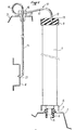
- a motor vehicle engine cooling radiator 1 to be mounted inside the engine compartment and surrounded by crosspieces or surrounding metal beams such as a lower beam 2, an upper beam 3 offset transversely from the first and an intermediate beam 4 located vertically between the other two, at the not shown grille.
- the radiator 1 rests in a known manner on the lower beam 2 by means of pins 5 clipped into said beam with the interposition of an elastic buffer 6 of rubber forming a stop, so as to leave a clearance 7 between the base 8 of the radiator and beam.
- This system makes it possible to quickly position and fix the radiator on the beam that is least accessible for mounting.
- the top 9 of the radiator is kept vertically pressurized by means of a wire spring assembly 10 comprising an elastic retaining branch 11 terminated in the form of a hook 12 and coming to press on the top 9 of the radiator with interposition of an elastic buffer 13, a spring loop 14, even an incomplete one, and a branch 15 for fixing substantially at right angles to the retaining branch 11, freely passing through the upper beam 3 while being guided by a clip 16 and hooked on the intermediate beam 4 located under the upper beam, vertical to the hole in the clip for the passage of the fixing branch.
- a wire spring assembly 10 comprising an elastic retaining branch 11 terminated in the form of a hook 12 and coming to press on the top 9 of the radiator with interposition of an elastic buffer 13, a spring loop 14, even an incomplete one, and a branch 15 for fixing substantially at right angles to the retaining branch 11, freely passing through the upper beam 3 while being guided by a clip 16 and hooked on the intermediate beam 4 located under the upper beam, vertical to the hole in the clip for the passage of the fixing branch.
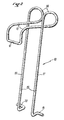
- FIG. 2 illustrates the conformation of the one-piece spring assembly 10 consisting of a go wire 17 and a return wire 18, parallel to the go.
- the free ends of the assembly form the end of the fixing branch 15, manipulated like an elastic bar, by bringing together the two strands whose ends 19, 20 are bent successively in two perpendicular planes to form hooking members in a lumen 21 of the intermediate beam 4 and bearing on the thickness of this lumen.
- the clip can be pre-assembled on the spring assembly and then clipped into the appropriate opening of the beam 3. It has upper grooves 22 on which the loops 14 of the spring and the strands 11 of the retaining branch are supported, collecting and transmitting the compressive force towards the fixing branch 15 by eliminating the torsional moment in the upper beam and leaving only a shearing force in the direction of its greater inertia.
- the intermediate beam 4 then supports all the significant forces.
- the elasticity of the retaining branch 11 makes it possible to quickly mount the radiator 1 and to absorb manufacturing dispersions while exerting sufficient vertical force on the radiator.
Description
La présente invention se rapporte à un dispositif de positionnement et de maintien d'un radiateur de refroidissement moteur d'un véhicule automobile sur les poutres métalliques du compartiment moteur, oelon un arrangement tel que défini dans le préambule de la revendication 1.The present invention relates to a device for positioning and holding an engine cooling radiator of a motor vehicle on the metal beams of the engine compartment, according to an arrangement as defined in the preamble of claim 1.
Le plus souvent, dans les arrangements de ce type, le radiateur est positionné et prend appui sur une poutre inférieure, par l'intermédiaire de pions de centrage et de tampons élastiques, puis il est fixé sur une poutre supérieure, décalée transversalement de la poutre inférieure, au moyen d'une pièce de liaison boulonnée sur la poutre supérieure et prenant appui au sommet du radiateur, avec interposition d'un autre tampon élastique, en exerçant une pression verticale suffisante sur le radiateur pour assurer son maintien efficace.Most often, in arrangements of this type, the radiator is positioned and supported on a lower beam, by means of centering pins and elastic buffers, then it is fixed on an upper beam, offset transversely from the beam lower, by means of a connecting piece bolted to the upper beam and bearing on the top of the radiator, with the interposition of another elastic buffer, by exerting sufficient vertical pressure on the radiator to ensure its effective maintenance.
Mais ce montage est long et malcommode du fait de la nécessité de maintenir le radiateur sous pression pendant le boulonnage de la pièce de fixation. De plus, il est nécessaire de régler la position de la pièce de liaison, par exemple au moyen de boutonnières et de cales, pour rattraper les nombreuses dispersions de cotes dues à la fabrication aussi bien du radiateur que de son environnement.However, this assembly is long and inconvenient because of the need to keep the radiator under pressure during the bolting of the fixing piece. In addition, it is necessary to adjust the position of the connecting piece, for example by means of buttonholes and shims, to compensate for the numerous dispersions of dimensions due to the manufacture of both the radiator and its environment.
Le réglage est d'autant plus difficile, voire même inutile, que la poutre supérieure est moins rigide. En effet, la pression exercée sur le radiateur risque d'être absorbée par une torsion correspondante de la poutre.The adjustment is all the more difficult, even useless, as the upper beam is less rigid. In fact, the pressure exerted on the radiator risks being absorbed by a corresponding torsion of the beam.
Une autre solution consiste à fixer le radiateur sur la poutre inférieure, après l'avoir positionné par rapport à la poutre supérieure. Mais cette fois l'accessibilité est plus difficile et le boulonnage et le réglage encore plus longs.Another solution is to fix the radiator on the lower beam, after having positioned it in relation to the upper beam. But this time accessibility is more difficult and bolting and adjustment even longer.
Le but de l'invention est de pallier les inconvénients précédents en proposant un dispositif de positionnement rapide et de maintien sous pression d'un radiateur par rapport à une structure de poutres environnantes entre lesquelles le radiateur doit être maintenue d'une part à sa base en prenant appui sur une poutre inférieure et d'autre part à son sommet par rapport à une poutre supérieure décalée transversalement de la poutre inférieure, sachant que la poutre supérieure ne peut être utilisée pour encaisser le couple de torsion transmis par l'organe de fixation.The object of the invention is to overcome the above drawbacks by proposing a device for rapid positioning and keeping a radiator under pressure with respect to a structure of surrounding beams between which the radiator must be held on the one hand at its base. by resting on a lower beam and on the other hand at its top relative to an upper beam offset transversely from the lower beam, knowing that the upper beam cannot be used to absorb the torsional torque transmitted by the fixing member .
Un autre but de l'invention est de proposer un dispositif à montage rapide, sans visserie, capable d'absorber automatiquement les différentes dispersions de fabrication.Another object of the invention is to provide a quick-mounting device, without screws, capable of automatically absorbing the various manufacturing dispersions.
Ces buts sont atteints grâce aux moyens déti- nis dans la partie caractérisante de la revendication 1.These aims are achieved by the means defined in the characterizing part of claim 1.
Le ressort comporte une branche à fixation élastique rapide sur la poutre intermédiaire et une branche élastique à peu près perpendiculaire à la première et reliée à celle-ci par une branche de ressort assurant la compression sur la pièce à maintenir.The spring comprises a branch with rapid elastic attachment to the intermediate beam and an elastic branch roughly perpendicular to the first and connected to the latter by a spring branch ensuring compression on the part to be maintained.
La branche de fixation ne fait que traverser la poutre supérieure sans la soumettre à aucune torsion si bien que les efforts sont encaissés par la poutre intermédiaire plus rigide, servant d'appui.The fixing branch only crosses the upper beam without subjecting it to any torsion so that the forces are absorbed by the more rigid intermediate beam, serving as a support.
La description qui suit d'un mode de réalisation de l'invention fait référence au dessin annexé sur lequel:
- - la figure 1 est une vue en coupe du dispositif appliqué au maintien d'un radiateur de véhicule,
- - la figure 2 représente en perspective, l'ensemble à ressort utilisé.
- FIG. 1 is a sectional view of the device applied to the maintenance of a vehicle radiator,
- - Figure 2 shows in perspective, the spring assembly used.
On reconnait sur la figure 1 un radiateur 1 de refroissement moteur de véhicule automobile devant être monté à l'intérieur du compartiment moteur et entouré de traverses ou de poutres métalliques environnantes telles qu'une poutre inférieure 2, une poutre supérieure 3 décalée transversalement de la première et une poutre intermédiaire 4 située verticalement entre les deux autres, au niveau de la calandre non représentée.We recognize in Figure 1 a motor vehicle engine cooling radiator 1 to be mounted inside the engine compartment and surrounded by crosspieces or surrounding metal beams such as a
Le radiateur 1 repose de façon connue sur la poutre inférieure 2 par l'intermédiaire de pions 5 clipsés dans ladite poutre avec interposition d'un tampon élastique 6 en caoutchouc formant butée, de manière à laisser un jeu 7 entre la base 8 du radiateur et la poutre. Ce système permet de positionner et de fixer rapidement le radiateur sur la poutre la moins accessible au montage.The radiator 1 rests in a known manner on the
Conformément à l'invention, le sommet 9 du radiateur est maintenu verticalement sous pression au moyen d'un ensemble 10 à ressort en fil comprenant une branche 11 de retenue élastique terminé en forme de crochet 12 et venant appuyer sur le sommet 9 du radiateur avec interposition d'un tampon élastique 13, une boucle 14 de ressort, même incomplète, et une branche 15 de fixation sensiblement à l'équerre avec la branche 11 de retenue, traversant librement la poutre supérieure 3 en étant guidée par une agrafe 16 et accrochée sur la poutre intermédiaire 4 située sous la poutre supérieure, à la verticale du trou de l'agrafe pour la passage de la branche de fixation.According to the invention, the
La figure 2 illustre la conformation de l'ensemble 10 à ressort monopièce constitué d'un fil aller 17 et d'un fil retour 18, parallèle à l'aller. Les extrémités libres de l'ensemble forment l'extrémité de la branche de fixation 15, manipulée comme une barrette élastique, par rapprochement des deux brins dont les bouts 19, 20 sont coudés successivement dans deux plans perpendiculaires pour former des organes d'accrochage dans une lumière 21 de la poutre intermédiaire 4 et d'appui sur l'épaisseur de cette lumière.FIG. 2 illustrates the conformation of the one-
Le crochet 12 de la branche de retenue transmettant, pour la compression du radiateur, l'élasticité de la boucle 14 de ressort, forme la jonction entre le fil aller 17 et le fil retour 18, l'écartement constant entre les deux brins étant déterminé par la largeur du crochet 12 et étant maintenu par l'agrafe 16 de guidage au cours du passage à travers la poutre supérieure 3.The
L'agrafe peut être prémontée sur l'ensemble à ressort puis clipsée dans l'ouverture appropriée de la poutre 3. Elle présente des rainures supérieures 22 sur lesquelles s'appuient les boucles 14 du ressort et les brins 11 de la branche de retenue, encaissant et transmettant l'effort de compression vers la branche de fixation 15 en supprimant le moment de torsion dans la poutre supérieure et en n'y laissant subsister qu'un effort tranchant dans le sens de sa plus grande inertie. La poutre intermédiaire 4 supporte alors tous les efforts importants.The clip can be pre-assembled on the spring assembly and then clipped into the appropriate opening of the
Par ailleurs, l'élasticité de la branche de retenue 11 permet de monter rapidement le radiateur 1 et d'absorber les dispersions de fabrication tout en exerçant un effort vertical suffisant sur le radiateur.Furthermore, the elasticity of the retaining branch 11 makes it possible to quickly mount the radiator 1 and to absorb manufacturing dispersions while exerting sufficient vertical force on the radiator.
Claims (5)
Applications Claiming Priority (2)
| Application Number | Priority Date | Filing Date | Title |
|---|---|---|---|
| FR8018384 | 1980-08-22 | ||
| FR8018384A FR2488953A1 (en) | 1980-08-22 | 1980-08-22 | FAST FASTENING DEVICE FORMED OF A SPRING ASSEMBLY |
Publications (2)
| Publication Number | Publication Date |
|---|---|
| EP0046566A1 EP0046566A1 (en) | 1982-03-03 |
| EP0046566B1 true EP0046566B1 (en) | 1985-03-27 |
Family
ID=9245365
Family Applications (1)
| Application Number | Title | Priority Date | Filing Date |
|---|---|---|---|
| EP81106406A Expired EP0046566B1 (en) | 1980-08-22 | 1981-08-18 | Quick fastening device formed by a spring unit for the cooling radiator of an engine |
Country Status (6)
| Country | Link |
|---|---|
| US (1) | US4417635A (en) |
| EP (1) | EP0046566B1 (en) |
| DE (1) | DE3169548D1 (en) |
| ES (1) | ES287286Y (en) |
| FR (1) | FR2488953A1 (en) |
| PT (1) | PT73539B (en) |
Cited By (6)
| Publication number | Priority date | Publication date | Assignee | Title |
|---|---|---|---|---|
| GB2132951A (en) * | 1982-12-16 | 1984-07-18 | Daimler Benz Ag | A mounting for the radiator of a vehicle |
| FR2579285A1 (en) * | 1985-03-20 | 1986-09-26 | Nissan Motor | AUTOMOTIVE RADIATOR MOUNTING SYSTEM |
| GB2174655A (en) * | 1985-04-30 | 1986-11-12 | Honda Motor Co Ltd | Motor vehicle radiators |
| EP0211253A1 (en) * | 1985-08-01 | 1987-02-25 | Bayerische Motoren Werke Aktiengesellschaft, Patentabteilung AJ-3 | Elastic support arrangement for radiators of internal-combustion engines, particularly in motor vehicles |
| GB2297066A (en) * | 1995-01-17 | 1996-07-24 | Suzuki Motor Co | Vehicular vibration isolating apparatus |
| EP1118830A2 (en) | 2000-01-22 | 2001-07-25 | Modine Manufacturing Company | Device for joining two heat exchangers |
Families Citing this family (12)
| Publication number | Priority date | Publication date | Assignee | Title |
|---|---|---|---|---|
| JPS6011317B2 (en) * | 1982-07-10 | 1985-03-25 | トヨタ自動車株式会社 | Radiator support device |
| US5216418A (en) * | 1990-03-13 | 1993-06-01 | Golden West Communications, Inc. | Emergency service rescue marker |
| DE4135387C1 (en) * | 1991-10-26 | 1992-07-09 | Mercedes-Benz Aktiengesellschaft, 7000 Stuttgart, De | |
| US5163505A (en) * | 1992-03-27 | 1992-11-17 | General Motors Corporation | Heater core retaining system |
| JP3085945B1 (en) * | 1999-02-24 | 2000-09-11 | 本田技研工業株式会社 | Vehicle radiator mounting structure |
| JP4461563B2 (en) * | 1999-10-20 | 2010-05-12 | 株式会社デンソー | Vehicle front-end structure |
| US6668955B1 (en) | 1999-12-06 | 2003-12-30 | General Motors Corporation | Methods and apparatus for mounting a heat exchanger to a vehicle |
| WO2002012817A1 (en) * | 2000-08-04 | 2002-02-14 | Showa Denko K.K. | Integrated heat exchanger |
| DE102004043354B4 (en) * | 2004-09-08 | 2010-06-24 | Hbpo Gmbh | Device for fastening a heat exchanger, in particular a coolant radiator for motor vehicles |
| US8235155B2 (en) * | 2009-06-02 | 2012-08-07 | Deere & Company | Radiator mounting arrangement on utility vehicle |
| JP6656949B2 (en) * | 2016-02-29 | 2020-03-04 | 三菱重工サーマルシステムズ株式会社 | Vehicle air conditioner |
| US11384922B2 (en) * | 2018-12-27 | 2022-07-12 | Eld Holdings, Llc | Clip holder for outdoor lights |
Family Cites Families (8)
| Publication number | Priority date | Publication date | Assignee | Title |
|---|---|---|---|---|
| US323262A (en) * | 1885-07-28 | Hat-holder | ||
| US2881721A (en) * | 1955-11-01 | 1959-04-14 | Deere & Co | Tractor mounted grain drill |
| US3333810A (en) * | 1966-01-26 | 1967-08-01 | Colt Mfg Company Inc | Battery holddown clamp |
| DE2018458C3 (en) * | 1970-04-17 | 1973-11-15 | Daimler-Benz Ag, 7000 Stuttgart | Elastic fastening of a radiator for motor vehicles |
| DE2557967C3 (en) * | 1975-12-22 | 1978-12-14 | Daimler-Benz Ag, 7000 Stuttgart | Radiator fastening of a motor vehicle |
| DE2634990C3 (en) * | 1976-08-04 | 1979-03-29 | Audi Nsu Auto Union Ag, 7107 Neckarsulm | Radiator mounting for motor vehicles |
| US4083312A (en) * | 1976-11-08 | 1978-04-11 | Holman Jr Robert E | Load holder end fitting |
| DE2706473C2 (en) * | 1977-02-16 | 1982-06-09 | Adam Opel AG, 6090 Rüsselsheim | Elastic fastening of a radiator for liquid-cooled internal combustion engines, in particular in motor vehicles |
-
1980
- 1980-08-22 FR FR8018384A patent/FR2488953A1/en active Granted
-
1981
- 1981-08-18 DE DE8181106406T patent/DE3169548D1/en not_active Expired
- 1981-08-18 EP EP81106406A patent/EP0046566B1/en not_active Expired
- 1981-08-19 PT PT73539A patent/PT73539B/en unknown
- 1981-08-19 US US06/294,217 patent/US4417635A/en not_active Expired - Fee Related
- 1981-08-21 ES ES1981287286U patent/ES287286Y/en not_active Expired
Cited By (10)
| Publication number | Priority date | Publication date | Assignee | Title |
|---|---|---|---|---|
| GB2132951A (en) * | 1982-12-16 | 1984-07-18 | Daimler Benz Ag | A mounting for the radiator of a vehicle |
| US4541645A (en) * | 1982-12-16 | 1985-09-17 | Daimler-Benz Aktiengesellschaft | Vehicle radiator mounting |
| FR2579285A1 (en) * | 1985-03-20 | 1986-09-26 | Nissan Motor | AUTOMOTIVE RADIATOR MOUNTING SYSTEM |
| GB2174655A (en) * | 1985-04-30 | 1986-11-12 | Honda Motor Co Ltd | Motor vehicle radiators |
| EP0211253A1 (en) * | 1985-08-01 | 1987-02-25 | Bayerische Motoren Werke Aktiengesellschaft, Patentabteilung AJ-3 | Elastic support arrangement for radiators of internal-combustion engines, particularly in motor vehicles |
| GB2297066A (en) * | 1995-01-17 | 1996-07-24 | Suzuki Motor Co | Vehicular vibration isolating apparatus |
| GB2297066B (en) * | 1995-01-17 | 1997-04-02 | Suzuki Motor Co | Vehicular vibration isolating apparatus |
| US5785140A (en) * | 1995-01-17 | 1998-07-28 | Suzuki Motor Corporation | Vehicular vibration isolating apparatus |
| EP1118830A2 (en) | 2000-01-22 | 2001-07-25 | Modine Manufacturing Company | Device for joining two heat exchangers |
| US6527044B2 (en) | 2000-01-22 | 2003-03-04 | Modine Manufacturing Company | Heat exchanger assembly |
Also Published As
| Publication number | Publication date |
|---|---|
| EP0046566A1 (en) | 1982-03-03 |
| PT73539A (en) | 1981-09-01 |
| ES287286U (en) | 1985-12-16 |
| PT73539B (en) | 1982-11-23 |
| FR2488953B1 (en) | 1984-10-26 |
| ES287286Y (en) | 1986-07-16 |
| US4417635A (en) | 1983-11-29 |
| DE3169548D1 (en) | 1985-05-02 |
| FR2488953A1 (en) | 1982-02-26 |
Similar Documents
| Publication | Publication Date | Title |
|---|---|---|
| EP0046566B1 (en) | Quick fastening device formed by a spring unit for the cooling radiator of an engine | |
| FR2632922A1 (en) | ||
| FR2783797A1 (en) | MOTOR VEHICLE, FRONT BLOCK FOR THIS VEHICLE AND METHOD OF MOUNTING THE VEHICLE | |
| EP0318346B1 (en) | Securing device for seat upholstery | |
| FR2935474A1 (en) | FIXING DEVICE FOR A HEAT EXCHANGER WITH FINS, IN PARTICULAR FOR MOTOR VEHICLES | |
| US4402380A (en) | Apparatus and method for supporting a transmission | |
| FR2665496A1 (en) | FLOATING CALIPER FOR DISC BRAKE WITH PARTIAL FITTINGS. | |
| FR2767293A1 (en) | FIXING DEVICE FOR A WINDSCREEN WIPER SYSTEM OF A MOTOR VEHICLE | |
| FR2890010A1 (en) | SLIDER FOR VEHICLE SEAT AND SEAT COMPRISING SUCH A SLIDER | |
| EP0478403B1 (en) | Mounting arrangement of a cooling radiator for a vehicle motor | |
| EP3822530B1 (en) | Aircraft comprising at least one connection device connecting an electrical cable and a conduit to a support | |
| ES2269530T3 (en) | WINDSHIELD CLEANING MECHANISM, PARTICULARLY FOR A VEHICLE. | |
| JPH04228647A (en) | Traction rope-securing means by jack lever of negative dobby machime | |
| US4732461A (en) | External rearview mirror with releasable catch mechanism for motor vehicles | |
| FR2771992A1 (en) | DEVICE FOR FIXING A VEHICLE SIDE FENDER ON A SUPPORT ELEMENT | |
| FR2833369A1 (en) | ARRANGEMENT FOR FIXING A WIPING DEVICE FOR THE ERASURE OF THE DRIVE SHAFT | |
| EP1598241B1 (en) | Arrangement of a trim element on its support inside of a vehicle | |
| FR2705074A1 (en) | Wiper device, in particular for motor vehicles. | |
| FR2898160A1 (en) | DEVICE FOR FASTENING TWO PIECES, ONE PLAQUE AGAINST THE OTHER, USING A CLIPS | |
| FR2492545A1 (en) | Metal frame spectacle nose pad - has clip ends on projection to fit into aperture in support | |
| FR2919247A3 (en) | Safety belt buckle's clasp fixing device for seat structure of motor vehicle, has fixation body formed from part engaged in buckle of strap and from keying part inserted in opening formed in seat structure | |
| EP0306582A1 (en) | Suspension device for the exhaust system of an internal-combustion engine | |
| EP1498305B1 (en) | Fastening device for a rear seat cushion of an automotive vehicle. | |
| EP1323992B1 (en) | Heater supporting device | |
| FR2889499A1 (en) | DEVICE FOR GUIDING A WIPER BLADE, IN PARTICULAR OF MOTOR VEHICLES |
Legal Events
| Date | Code | Title | Description |
|---|---|---|---|
| PUAI | Public reference made under article 153(3) epc to a published international application that has entered the european phase |
Free format text: ORIGINAL CODE: 0009012 |
|
| AK | Designated contracting states |
Designated state(s): BE DE GB IT NL SE |
|
| 17P | Request for examination filed |
Effective date: 19820202 |
|
| RBV | Designated contracting states (corrected) |
Designated state(s): BE DE GB IT NL SE |
|
| ITF | It: translation for a ep patent filed |
Owner name: BARZANO' E ZANARDO MILANO S.P.A. |
|
| GRAA | (expected) grant |
Free format text: ORIGINAL CODE: 0009210 |
|
| AK | Designated contracting states |
Designated state(s): BE DE GB IT NL SE |
|
| REF | Corresponds to: |
Ref document number: 3169548 Country of ref document: DE Date of ref document: 19850502 |
|
| PLBE | No opposition filed within time limit |
Free format text: ORIGINAL CODE: 0009261 |
|
| STAA | Information on the status of an ep patent application or granted ep patent |
Free format text: STATUS: NO OPPOSITION FILED WITHIN TIME LIMIT |
|
| 26N | No opposition filed | ||
| PGFP | Annual fee paid to national office [announced via postgrant information from national office to epo] |
Ref country code: GB Payment date: 19920715 Year of fee payment: 12 |
|
| PGFP | Annual fee paid to national office [announced via postgrant information from national office to epo] |
Ref country code: SE Payment date: 19920716 Year of fee payment: 12 Ref country code: DE Payment date: 19920716 Year of fee payment: 12 |
|
| PGFP | Annual fee paid to national office [announced via postgrant information from national office to epo] |
Ref country code: BE Payment date: 19920717 Year of fee payment: 12 |
|
| ITTA | It: last paid annual fee | ||
| PGFP | Annual fee paid to national office [announced via postgrant information from national office to epo] |
Ref country code: NL Payment date: 19920831 Year of fee payment: 12 |
|
| PG25 | Lapsed in a contracting state [announced via postgrant information from national office to epo] |
Ref country code: GB Effective date: 19930818 |
|
| PG25 | Lapsed in a contracting state [announced via postgrant information from national office to epo] |
Ref country code: SE Effective date: 19930819 |
|
| PG25 | Lapsed in a contracting state [announced via postgrant information from national office to epo] |
Ref country code: BE Effective date: 19930831 |
|
| BERE | Be: lapsed |
Owner name: REGIE NATIONALE DES USINES RENAULT Effective date: 19930831 |
|
| PG25 | Lapsed in a contracting state [announced via postgrant information from national office to epo] |
Ref country code: NL Effective date: 19940301 |
|
| NLV4 | Nl: lapsed or anulled due to non-payment of the annual fee | ||
| GBPC | Gb: european patent ceased through non-payment of renewal fee |
Effective date: 19930818 |
|
| PG25 | Lapsed in a contracting state [announced via postgrant information from national office to epo] |
Ref country code: DE Effective date: 19940503 |
|
| EUG | Se: european patent has lapsed |
Ref document number: 81106406.2 Effective date: 19940310 |