EP0046016B1 - Device for slicing through a plug of potting compound - Google Patents
Device for slicing through a plug of potting compound Download PDFInfo
- Publication number
- EP0046016B1 EP0046016B1 EP81303231A EP81303231A EP0046016B1 EP 0046016 B1 EP0046016 B1 EP 0046016B1 EP 81303231 A EP81303231 A EP 81303231A EP 81303231 A EP81303231 A EP 81303231A EP 0046016 B1 EP0046016 B1 EP 0046016B1
- Authority
- EP
- European Patent Office
- Prior art keywords
- plug
- blade
- cutting
- slicing
- potting compound
- Prior art date
- Legal status (The legal status is an assumption and is not a legal conclusion. Google has not performed a legal analysis and makes no representation as to the accuracy of the status listed.)
- Expired
Links
Images



Classifications
-
- B—PERFORMING OPERATIONS; TRANSPORTING
- B01—PHYSICAL OR CHEMICAL PROCESSES OR APPARATUS IN GENERAL
- B01D—SEPARATION
- B01D63/00—Apparatus in general for separation processes using semi-permeable membranes
- B01D63/02—Hollow fibre modules
- B01D63/021—Manufacturing thereof
- B01D63/022—Encapsulating hollow fibres
- B01D63/0224—Opening the fibre ends after encapsulation
-
- B—PERFORMING OPERATIONS; TRANSPORTING
- B26—HAND CUTTING TOOLS; CUTTING; SEVERING
- B26D—CUTTING; DETAILS COMMON TO MACHINES FOR PERFORATING, PUNCHING, CUTTING-OUT, STAMPING-OUT OR SEVERING
- B26D3/00—Cutting work characterised by the nature of the cut made; Apparatus therefor
- B26D3/06—Grooving involving removal of material from the surface of the work
-
- Y—GENERAL TAGGING OF NEW TECHNOLOGICAL DEVELOPMENTS; GENERAL TAGGING OF CROSS-SECTIONAL TECHNOLOGIES SPANNING OVER SEVERAL SECTIONS OF THE IPC; TECHNICAL SUBJECTS COVERED BY FORMER USPC CROSS-REFERENCE ART COLLECTIONS [XRACs] AND DIGESTS
- Y10—TECHNICAL SUBJECTS COVERED BY FORMER USPC
- Y10S—TECHNICAL SUBJECTS COVERED BY FORMER USPC CROSS-REFERENCE ART COLLECTIONS [XRACs] AND DIGESTS
- Y10S83/00—Cutting
- Y10S83/917—Notching
-
- Y—GENERAL TAGGING OF NEW TECHNOLOGICAL DEVELOPMENTS; GENERAL TAGGING OF CROSS-SECTIONAL TECHNOLOGIES SPANNING OVER SEVERAL SECTIONS OF THE IPC; TECHNICAL SUBJECTS COVERED BY FORMER USPC CROSS-REFERENCE ART COLLECTIONS [XRACs] AND DIGESTS
- Y10—TECHNICAL SUBJECTS COVERED BY FORMER USPC
- Y10T—TECHNICAL SUBJECTS COVERED BY FORMER US CLASSIFICATION
- Y10T83/00—Cutting
- Y10T83/869—Means to drive or to guide tool
- Y10T83/8773—Bevel or miter cut
-
- Y—GENERAL TAGGING OF NEW TECHNOLOGICAL DEVELOPMENTS; GENERAL TAGGING OF CROSS-SECTIONAL TECHNOLOGIES SPANNING OVER SEVERAL SECTIONS OF THE IPC; TECHNICAL SUBJECTS COVERED BY FORMER USPC CROSS-REFERENCE ART COLLECTIONS [XRACs] AND DIGESTS
- Y10—TECHNICAL SUBJECTS COVERED BY FORMER USPC
- Y10T—TECHNICAL SUBJECTS COVERED BY FORMER US CLASSIFICATION
- Y10T83/00—Cutting
- Y10T83/869—Means to drive or to guide tool
- Y10T83/8821—With simple rectilinear reciprocating motion only
- Y10T83/8854—Progressively cutting
-
- Y—GENERAL TAGGING OF NEW TECHNOLOGICAL DEVELOPMENTS; GENERAL TAGGING OF CROSS-SECTIONAL TECHNOLOGIES SPANNING OVER SEVERAL SECTIONS OF THE IPC; TECHNICAL SUBJECTS COVERED BY FORMER USPC CROSS-REFERENCE ART COLLECTIONS [XRACs] AND DIGESTS
- Y10—TECHNICAL SUBJECTS COVERED BY FORMER USPC
- Y10T—TECHNICAL SUBJECTS COVERED BY FORMER US CLASSIFICATION
- Y10T83/00—Cutting
- Y10T83/869—Means to drive or to guide tool
- Y10T83/8821—With simple rectilinear reciprocating motion only
- Y10T83/8858—Fluid pressure actuated
-
- Y—GENERAL TAGGING OF NEW TECHNOLOGICAL DEVELOPMENTS; GENERAL TAGGING OF CROSS-SECTIONAL TECHNOLOGIES SPANNING OVER SEVERAL SECTIONS OF THE IPC; TECHNICAL SUBJECTS COVERED BY FORMER USPC CROSS-REFERENCE ART COLLECTIONS [XRACs] AND DIGESTS
- Y10—TECHNICAL SUBJECTS COVERED BY FORMER USPC
- Y10T—TECHNICAL SUBJECTS COVERED BY FORMER US CLASSIFICATION
- Y10T83/00—Cutting
- Y10T83/929—Tool or tool with support
- Y10T83/9454—Reciprocable type
Definitions
- membranes used in these methods are contained in vessels called modules which comprise a container having various inlet and outlet ports and an assembly of membranes within the container.
- modules which comprise a container having various inlet and outlet ports and an assembly of membranes within the container.
- the internal arrangements of the modules are such as to permit the introduction of a feed stream either under pressure or not on the upstream faces of the membranes and means are provided for collecting permeate which passes through the membranes and emerges on their downstream faces. Means are also, of course, provided for keeping the feed stream and the permeate from commingling.
- Membranes have been fabricated in various shapes, such as (1) flat sheets which may be supported in a plate and frame structure similar to a filter press; (2) initially flat sheets which are rolled into spirals with spacing materials interleaved with the membrane and the assembly being sealed to provide spiroidal channels permitting the passage of a feed on one side of the rolled membrane through spaces to the opposite side of the membrane; (3) tubes which line the inner surface of a reinforced braid, the braid itself sometimes being a component in a larger tube; and (4) in the form of open-ended hollow fibres so arranged and sealed into header plates as to provide a separation of the flow over the external surfaces of the hollow fibres from flows within the bores of the hollow- fibres which ensue by virtue of the passage of permeant through the membranes which form the walls of the hollow fibres.
- DE - C - 50 356 discloses a device which is intended for cutting grooves in cardboard and which includes a V-shaped or inverse plough- shaped cutting blade. This device is not however suitable for cutting recesses in the potting compound in hollow fibre modules such as that just described and it has been found that the necessary configuration and positions of the recesses can be achieved only with great difficulty and consumption of time and that repetition could not be achieved with accuracy by the use of known methods and equipment.
- the present invention provides a device for slicing through a plug of potting compound forming a module termination plug which enables the plug to be sliced through accurately and quickly and with a high degree of predictable repetition to expose the bores of the fibres embedded in the plug while maintaining structural integrity of the plug.
- such a device includes a cutting blade of inverse plough-shape and is characterised by including, in combination with the cutting blade, a housing for holding the plug and means for moving the blade between a retracted position and a cutting position in a cutting stroke, and the cutting blade comprising two sides which form a V resulting at the cutting zone of the blade in the blade having two separate sub-blades each of which has a uniform side reflex angle and two distinct sections of different side rake angles.
- each of the sub-blades has a cutting edge depressed from the horizontal at an angle of thirty degrees with one rake angle being of five degrees and the other rake angle being of fifteen degrees.
- the housing includes a receptacle in which the plug is contained and a notch is formed in the receptacle exposing the plug to the cutting blade as the blade moves to its cutting position.
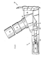
- the slicing device shown in the drawings includes a fixed assembly 10 for supporting a module 12 in position and a movable assembly 14 for reciprocating a cutting blade 16 into and out of a slicing position to slice the module 12.
- the fixed assembly 10 includes a housing 18 which supports a cylindrical receptacle 20 within which the module 12 is contained with a portion of a plug 22 of the module (see Figure 4) exposed to the cutting blade 16 through a notch 24 in the receptacle. During reciprocal movement of the blade, the blade is guided to the notch by guide means 26 which is also mounted on the housing 18.
- the cutting blade 16 is mounted on a piston rod 28 of a slow speed pneumatic cylinder 30 and is of a compound V or inverse plough (mirror image of a plough) configuration so that it digs into the potting compound or plug 22 while undergoing a minimum resistance from the material being sliced.
- the cutting blade 16 is formed of D2 tool steel which is hardened to Rockwell C 60, ground and stress relieved so that it is hard enough to give in the face of the wedging action which it encounters as it enters the potting compound.
- the blade 16 can be formed out of stock of triangular section with one surface hollowed out to provide two sides which form a V. As shown in Figures 6 to 8 of the drawings a channel of the cut out portion is defined essentially by lines 33a, 33b and 33c. The V-shape and the portion cut out result at the cutting zone in two separate sub-blades, 34 and 36, each with its own cutting edge 34a and 36a respectively.
- the line 33a meets the line 32 of the cutting zone.
- Each of the sub-blades has a uniform side reflex angle 34b and 36b respectively, but each blade has two distinct sections of different side rake or clearance angles.
- the sub-blades are mirror images of each other.
- the rake angle 0 of sector 34c is five degrees while the rake angle 0' of sector 34d is fifteen degrees.
- the situation is similar but reversed for the sub-blade 36 as is obvious from the drawings.
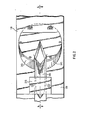
- the module 12 is placed in position within the receptacle 20 when the blade 16 is in the position shown in Figures 1, 2 and 4. A portion of the plug 22 protrudes at the notch 24.
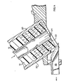
- the cylinder 30 is actuated to move the piston rod 28 with the blade 16 attached to the right as seen in Figures 3 and 5 so that the blade, guided by the guide 26, slices the potting compound as desired to separate a portion 30a therefrom as seen in Figure 5.
Landscapes
- Engineering & Computer Science (AREA)
- Manufacturing & Machinery (AREA)
- Chemical & Material Sciences (AREA)
- Chemical Kinetics & Catalysis (AREA)
- Life Sciences & Earth Sciences (AREA)
- Forests & Forestry (AREA)
- Mechanical Engineering (AREA)
- Separation Using Semi-Permeable Membranes (AREA)
Abstract
Description
- The use of membranes to effect separation of gas/gas, liquid/liquid, and liquid/solid mixtures and solutions has achieved general industrial applicability by various methods, among them being ultrafiltration, hyperfiltration, reverse osmosis and dialysis. In general, membranes used in these methods are contained in vessels called modules which comprise a container having various inlet and outlet ports and an assembly of membranes within the container. The internal arrangements of the modules are such as to permit the introduction of a feed stream either under pressure or not on the upstream faces of the membranes and means are provided for collecting permeate which passes through the membranes and emerges on their downstream faces. Means are also, of course, provided for keeping the feed stream and the permeate from commingling.
- Membranes have been fabricated in various shapes, such as (1) flat sheets which may be supported in a plate and frame structure similar to a filter press; (2) initially flat sheets which are rolled into spirals with spacing materials interleaved with the membrane and the assembly being sealed to provide spiroidal channels permitting the passage of a feed on one side of the rolled membrane through spaces to the opposite side of the membrane; (3) tubes which line the inner surface of a reinforced braid, the braid itself sometimes being a component in a larger tube; and (4) in the form of open-ended hollow fibres so arranged and sealed into header plates as to provide a separation of the flow over the external surfaces of the hollow fibres from flows within the bores of the hollow- fibres which ensue by virtue of the passage of permeant through the membranes which form the walls of the hollow fibres.
- Of particular interest is the use of hollow fibres assembled in a modular form to provide the desired separation.
- In our European Patent Application No. 79301885.4 which was published on 2nd April 1980 (Publication No. 0,009,374), various techniques for the selection and winding of hollow fibres and the fabrication and assembly of such fibres into modular form are described. It is noted that a significant consideration in this work is the manner and means of terminating the hollow tubular bundle of fibres so that the ends of the fibres can be opened to allow for the recovery of the permeate from within the hollow fibres and at the same time provide suitable support for the fibres to resist the thrust forces developed by the internal pressures within the module in which the fibres are contained. In the above Application, the use of potting compound solidified around the ends of the fibres is described and slices are taken through the potting compound to expose the fibre bores while providing adequate support to resist internal pressure. The provision of recesses of suitable configuration and position in the potting compound within which the fibre ends are disposed is illustrated.
- DE - C - 50 356 discloses a device which is intended for cutting grooves in cardboard and which includes a V-shaped or inverse plough- shaped cutting blade. This device is not however suitable for cutting recesses in the potting compound in hollow fibre modules such as that just described and it has been found that the necessary configuration and positions of the recesses can be achieved only with great difficulty and consumption of time and that repetition could not be achieved with accuracy by the use of known methods and equipment.
- The present invention provides a device for slicing through a plug of potting compound forming a module termination plug which enables the plug to be sliced through accurately and quickly and with a high degree of predictable repetition to expose the bores of the fibres embedded in the plug while maintaining structural integrity of the plug.
- According to this invention, such a device includes a cutting blade of inverse plough-shape and is characterised by including, in combination with the cutting blade, a housing for holding the plug and means for moving the blade between a retracted position and a cutting position in a cutting stroke, and the cutting blade comprising two sides which form a V resulting at the cutting zone of the blade in the blade having two separate sub-blades each of which has a uniform side reflex angle and two distinct sections of different side rake angles.
- Preferably each of the sub-blades has a cutting edge depressed from the horizontal at an angle of thirty degrees with one rake angle being of five degrees and the other rake angle being of fifteen degrees.
- Preferably also, the housing includes a receptacle in which the plug is contained and a notch is formed in the receptacle exposing the plug to the cutting blade as the blade moves to its cutting position.
- An example of a device in accordance with the invention is illustrated in the accompanying drawings in which:-
- Figure 1 is a side elevation of the device;
- Figure 2 is a partial underneath plan view of the device showing a cutting blade and a base platform, the blade being retracted from a plug receptacle;
- Figure 3 is a view similar to Figure 2 but with the blade fully advanced below the plug receptacle;
- Figure 4 is a sectional view taken in the direction of the arrows on the line 4-4 in Figure 2 illustrating the cutting blade approaching a module termination plug positioned in the receptacle;
- Figure 5 is a sectional view similar to Figure 4 but taken in the direction of the arrows on the line 5-5 in Figure 3 illustrating a slice being taken from the module termination plug; and
- Figures 6, 7, 8 and 9 are views of the cutting blade of the device taken from different directions to show the configuration of the blade,
- Figure 6 being a perspective view looking down on the blade as viewed in Figure 1, Figures 7 and 8 being bottom and end views respectively and Figure 9 being a partial sectional view taken in the direction of the arrows on the line 9-9 in Figure 6.
- The slicing device shown in the drawings includes a
fixed assembly 10 for supporting amodule 12 in position and amovable assembly 14 for reciprocating acutting blade 16 into and out of a slicing position to slice themodule 12. - The
fixed assembly 10 includes ahousing 18 which supports acylindrical receptacle 20 within which themodule 12 is contained with a portion of aplug 22 of the module (see Figure 4) exposed to thecutting blade 16 through anotch 24 in the receptacle. During reciprocal movement of the blade, the blade is guided to the notch by guide means 26 which is also mounted on thehousing 18. - The
cutting blade 16 is mounted on apiston rod 28 of a slow speedpneumatic cylinder 30 and is of a compound V or inverse plough (mirror image of a plough) configuration so that it digs into the potting compound or plug 22 while undergoing a minimum resistance from the material being sliced. Thecutting blade 16 is formed of D2 tool steel which is hardened to Rockwell C 60, ground and stress relieved so that it is hard enough to give in the face of the wedging action which it encounters as it enters the potting compound. - The
blade 16 can be formed out of stock of triangular section with one surface hollowed out to provide two sides which form a V. As shown in Figures 6 to 8 of the drawings a channel of the cut out portion is defined essentially bylines own cutting edge line 33a meets theline 32 of the cutting zone. Each of the sub-blades has a uniformside reflex angle - Thus in the illustrated example where the
cutting edges sector 34c is five degrees while the rake angle 0' of sector 34d is fifteen degrees. The situation is similar but reversed for thesub-blade 36 as is obvious from the drawings. - In use, the
module 12 is placed in position within thereceptacle 20 when theblade 16 is in the position shown in Figures 1, 2 and 4. A portion of theplug 22 protrudes at thenotch 24. Thecylinder 30 is actuated to move thepiston rod 28 with theblade 16 attached to the right as seen in Figures 3 and 5 so that the blade, guided by theguide 26, slices the potting compound as desired to separate aportion 30a therefrom as seen in Figure 5.
Claims (3)
Priority Applications (1)
| Application Number | Priority Date | Filing Date | Title |
|---|---|---|---|
| AT81303231T ATE9773T1 (en) | 1980-08-11 | 1981-07-14 | CUTTING MACHINE FOR HOLLOW FIBER MODULES. |
Applications Claiming Priority (2)
| Application Number | Priority Date | Filing Date | Title |
|---|---|---|---|
| US176720 | 1980-08-11 | ||
| US06/176,720 US4328730A (en) | 1980-08-11 | 1980-08-11 | Means for slicing module termination plug |
Publications (2)
| Publication Number | Publication Date |
|---|---|
| EP0046016A1 EP0046016A1 (en) | 1982-02-17 |
| EP0046016B1 true EP0046016B1 (en) | 1984-10-10 |
Family
ID=22645561
Family Applications (1)
| Application Number | Title | Priority Date | Filing Date |
|---|---|---|---|
| EP81303231A Expired EP0046016B1 (en) | 1980-08-11 | 1981-07-14 | Device for slicing through a plug of potting compound |
Country Status (4)
| Country | Link |
|---|---|
| US (1) | US4328730A (en) |
| EP (1) | EP0046016B1 (en) |
| AT (1) | ATE9773T1 (en) |
| DE (1) | DE3166598D1 (en) |
Families Citing this family (1)
| Publication number | Priority date | Publication date | Assignee | Title |
|---|---|---|---|---|
| USD735010S1 (en) * | 2013-07-08 | 2015-07-28 | 3M Innovative Properties Company | Window film attachment applicator tool |
Family Cites Families (11)
| Publication number | Priority date | Publication date | Assignee | Title |
|---|---|---|---|---|
| DE50356C (en) * | E. SALTZ- | KORN, Consul, und L. NICOLAI in Dresden. F., ' Löbtauerstrafse 21 | Cardboard cutting knife | ||
| DE82085C (en) * | ||||
| US701963A (en) * | 1900-01-10 | 1902-06-10 | Eugene H Taylor | Machine for mitering and cornering box-blanks. |
| US1114154A (en) * | 1914-05-08 | 1914-10-20 | Charles E Leach & Company | Shoe-heel-reducing device. |
| US2936665A (en) * | 1957-07-26 | 1960-05-17 | Naffin Alfred | Shear for forming rounded corners on rectangular cards, etc. |
| US3073195A (en) * | 1957-11-25 | 1963-01-15 | Vogel Tool & Die Corp | Apparatus for notching the ends of tubing in the preparation of tubular assemblies |
| US3153963A (en) * | 1963-06-25 | 1964-10-27 | Vogel Tool & Die Corp | Apparatus for shearing the ends of tubing |
| US3227025A (en) * | 1963-10-02 | 1966-01-04 | Paul E Macmillan | Mitering tool |
| US3299759A (en) * | 1965-07-20 | 1967-01-24 | Warwick Electronics Inc | Miter cutter |
| US3503288A (en) * | 1967-05-22 | 1970-03-31 | Lennart Gerhard Swartling | Apparatus for transversely cutting a plurality of small hollow plastic tubular elements embedded in a solid matrix of plastic material to maintain the ends thereof open |
| BE792294A (en) * | 1971-12-15 | 1973-06-05 | Knogo Corp | METHOD AND APPARATUS FOR SEPARATING FIXING DEVICES |
-
1980
- 1980-08-11 US US06/176,720 patent/US4328730A/en not_active Expired - Lifetime
-
1981
- 1981-07-14 AT AT81303231T patent/ATE9773T1/en active
- 1981-07-14 EP EP81303231A patent/EP0046016B1/en not_active Expired
- 1981-07-14 DE DE8181303231T patent/DE3166598D1/en not_active Expired
Also Published As
| Publication number | Publication date |
|---|---|
| ATE9773T1 (en) | 1984-10-15 |
| EP0046016A1 (en) | 1982-02-17 |
| DE3166598D1 (en) | 1984-11-15 |
| US4328730A (en) | 1982-05-11 |
Similar Documents
| Publication | Publication Date | Title |
|---|---|---|
| DE60303122T2 (en) | MICROFLUIDIC SEPARATION COLLONS AND THEIR MANUFACTURING METHOD | |
| DE60214167T2 (en) | Multilayered microfluidic splitter | |
| EP0487576B1 (en) | Method and apparatus for effecting the transfer of heat or mass through a membrane involving the use of vortices | |
| DE19700231C2 (en) | Device for filtering and separating flow media | |
| US3695444A (en) | Membrane support | |
| US6852222B2 (en) | Multiple well plate with adhesive bonded filter | |
| EP0096340B1 (en) | Membrane module and its use in the separation of liquids by pervaporation | |
| EP0491574A1 (en) | Method and apparatus for separating thin-walled, multiport micro-extrusions | |
| CA1302904C (en) | High recovery spiral wound membrane element | |
| EP0111423A1 (en) | Transfer membrane apparatus | |
| GB2329132A (en) | Flow control in tangential flow membrane filtration; pressure gauge | |
| DE3882607T2 (en) | Multi-leaf membrane module. | |
| KR840008122A (en) | Membrane oxygen supply | |
| DE69806779T2 (en) | DYNAMIC MEMBRANE FILTRATION BY MEANS OF VIBRATIONS | |
| DE2444663C2 (en) | Blade of the shaving head of a dry razor | |
| EP0046016A1 (en) | Device for slicing through a plug of potting compound | |
| DE3882378T2 (en) | TRANSMISSION MEMBRANE. | |
| DE2342324C3 (en) | Method and device for separating immiscible liquids | |
| EP0855211A1 (en) | Membrane separation apparatus | |
| US3909418A (en) | Method for forming a laminate member and apparatus utilizing the same | |
| CA1204674A (en) | Apparatus for separating liquid feed mixtures into two fractions by means of semipermeable membranes | |
| DE3512488C2 (en) | Device for dividing frozen food, in particular fish | |
| AT393807B (en) | WAFFLE BLOCK CUTTER | |
| DE3507532C2 (en) | Device for filtering and separating liquid and gaseous media | |
| FI67044C (en) | CHECKING FACILITY AVSKAERNING AV SINSEMELLAN PARALLELLA LAENGSELEMENT I KORSVERK ELLER GALLER |
Legal Events
| Date | Code | Title | Description |
|---|---|---|---|
| PUAI | Public reference made under article 153(3) epc to a published international application that has entered the european phase |
Free format text: ORIGINAL CODE: 0009012 |
|
| AK | Designated contracting states |
Designated state(s): AT BE CH DE FR GB IT LI LU NL |
|
| 17P | Request for examination filed |
Effective date: 19820713 |
|
| RAP1 | Party data changed (applicant data changed or rights of an application transferred) |
Owner name: ALBANY INTERNATIONAL CORP. |
|
| ITF | It: translation for a ep patent filed | ||
| GRAA | (expected) grant |
Free format text: ORIGINAL CODE: 0009210 |
|
| AK | Designated contracting states |
Designated state(s): AT BE CH DE FR GB IT LI LU NL |
|
| REF | Corresponds to: |
Ref document number: 9773 Country of ref document: AT Date of ref document: 19841015 Kind code of ref document: T |
|
| REF | Corresponds to: |
Ref document number: 3166598 Country of ref document: DE Date of ref document: 19841115 |
|
| ET | Fr: translation filed | ||
| PLBE | No opposition filed within time limit |
Free format text: ORIGINAL CODE: 0009261 |
|
| STAA | Information on the status of an ep patent application or granted ep patent |
Free format text: STATUS: NO OPPOSITION FILED WITHIN TIME LIMIT |
|
| 26N | No opposition filed | ||
| ITTA | It: last paid annual fee | ||
| EPTA | Lu: last paid annual fee | ||
| PGFP | Annual fee paid to national office [announced via postgrant information from national office to epo] |
Ref country code: GB Payment date: 19970707 Year of fee payment: 17 |
|
| PGFP | Annual fee paid to national office [announced via postgrant information from national office to epo] |
Ref country code: FR Payment date: 19970709 Year of fee payment: 17 |
|
| PGFP | Annual fee paid to national office [announced via postgrant information from national office to epo] |
Ref country code: AT Payment date: 19970715 Year of fee payment: 17 |
|
| PGFP | Annual fee paid to national office [announced via postgrant information from national office to epo] |
Ref country code: DE Payment date: 19970718 Year of fee payment: 17 |
|
| PGFP | Annual fee paid to national office [announced via postgrant information from national office to epo] |
Ref country code: CH Payment date: 19970730 Year of fee payment: 17 |
|
| PGFP | Annual fee paid to national office [announced via postgrant information from national office to epo] |
Ref country code: NL Payment date: 19970731 Year of fee payment: 17 |
|
| PGFP | Annual fee paid to national office [announced via postgrant information from national office to epo] |
Ref country code: LU Payment date: 19970814 Year of fee payment: 17 |
|
| PGFP | Annual fee paid to national office [announced via postgrant information from national office to epo] |
Ref country code: BE Payment date: 19970828 Year of fee payment: 17 |
|
| PG25 | Lapsed in a contracting state [announced via postgrant information from national office to epo] |
Ref country code: LU Free format text: LAPSE BECAUSE OF NON-PAYMENT OF DUE FEES Effective date: 19980714 Ref country code: GB Free format text: LAPSE BECAUSE OF NON-PAYMENT OF DUE FEES Effective date: 19980714 Ref country code: AT Free format text: LAPSE BECAUSE OF NON-PAYMENT OF DUE FEES Effective date: 19980714 |
|
| PG25 | Lapsed in a contracting state [announced via postgrant information from national office to epo] |
Ref country code: LI Free format text: LAPSE BECAUSE OF NON-PAYMENT OF DUE FEES Effective date: 19980731 Ref country code: CH Free format text: LAPSE BECAUSE OF NON-PAYMENT OF DUE FEES Effective date: 19980731 Ref country code: BE Free format text: LAPSE BECAUSE OF NON-PAYMENT OF DUE FEES Effective date: 19980731 |
|
| BERE | Be: lapsed |
Owner name: ALBANY INTERNATIONAL CORP. Effective date: 19980731 |
|
| PG25 | Lapsed in a contracting state [announced via postgrant information from national office to epo] |
Ref country code: NL Free format text: LAPSE BECAUSE OF NON-PAYMENT OF DUE FEES Effective date: 19990201 |
|
| GBPC | Gb: european patent ceased through non-payment of renewal fee |
Effective date: 19980714 |
|
| REG | Reference to a national code |
Ref country code: CH Ref legal event code: PL |
|
| PG25 | Lapsed in a contracting state [announced via postgrant information from national office to epo] |
Ref country code: FR Free format text: LAPSE BECAUSE OF NON-PAYMENT OF DUE FEES Effective date: 19990331 |
|
| NLV4 | Nl: lapsed or anulled due to non-payment of the annual fee |
Effective date: 19990201 |
|
| PG25 | Lapsed in a contracting state [announced via postgrant information from national office to epo] |
Ref country code: DE Free format text: LAPSE BECAUSE OF NON-PAYMENT OF DUE FEES Effective date: 19990501 |
|
| REG | Reference to a national code |
Ref country code: FR Ref legal event code: ST |