EP0046010A1 - Fastener and driver combination - Google Patents
Fastener and driver combination Download PDFInfo
- Publication number
- EP0046010A1 EP0046010A1 EP81303152A EP81303152A EP0046010A1 EP 0046010 A1 EP0046010 A1 EP 0046010A1 EP 81303152 A EP81303152 A EP 81303152A EP 81303152 A EP81303152 A EP 81303152A EP 0046010 A1 EP0046010 A1 EP 0046010A1
- Authority
- EP
- European Patent Office
- Prior art keywords
- driver
- recess
- grooves
- wings
- taper
- Prior art date
- Legal status (The legal status is an assumption and is not a legal conclusion. Google has not performed a legal analysis and makes no representation as to the accuracy of the status listed.)
- Granted
Links
- 230000035515 penetration Effects 0.000 description 7
- 238000004519 manufacturing process Methods 0.000 description 3
- 238000003780 insertion Methods 0.000 description 1
- 230000037431 insertion Effects 0.000 description 1
- 239000000463 material Substances 0.000 description 1
- 239000002184 metal Substances 0.000 description 1
- 230000004048 modification Effects 0.000 description 1
- 238000012986 modification Methods 0.000 description 1
- 238000010079 rubber tapping Methods 0.000 description 1
- 238000004904 shortening Methods 0.000 description 1
Images

Classifications
-
- B—PERFORMING OPERATIONS; TRANSPORTING
- B25—HAND TOOLS; PORTABLE POWER-DRIVEN TOOLS; MANIPULATORS
- B25B—TOOLS OR BENCH DEVICES NOT OTHERWISE PROVIDED FOR, FOR FASTENING, CONNECTING, DISENGAGING OR HOLDING
- B25B15/00—Screwdrivers
-
- B—PERFORMING OPERATIONS; TRANSPORTING
- B25—HAND TOOLS; PORTABLE POWER-DRIVEN TOOLS; MANIPULATORS
- B25B—TOOLS OR BENCH DEVICES NOT OTHERWISE PROVIDED FOR, FOR FASTENING, CONNECTING, DISENGAGING OR HOLDING
- B25B15/00—Screwdrivers
- B25B15/001—Screwdrivers characterised by material or shape of the tool bit
- B25B15/004—Screwdrivers characterised by material or shape of the tool bit characterised by cross-section
- B25B15/005—Screwdrivers characterised by material or shape of the tool bit characterised by cross-section with cross- or star-shaped cross-section
-
- F—MECHANICAL ENGINEERING; LIGHTING; HEATING; WEAPONS; BLASTING
- F16—ENGINEERING ELEMENTS AND UNITS; GENERAL MEASURES FOR PRODUCING AND MAINTAINING EFFECTIVE FUNCTIONING OF MACHINES OR INSTALLATIONS; THERMAL INSULATION IN GENERAL
- F16B—DEVICES FOR FASTENING OR SECURING CONSTRUCTIONAL ELEMENTS OR MACHINE PARTS TOGETHER, e.g. NAILS, BOLTS, CIRCLIPS, CLAMPS, CLIPS OR WEDGES; JOINTS OR JOINTING
- F16B23/00—Specially shaped nuts or heads of bolts or screws for rotations by a tool
- F16B23/0007—Specially shaped nuts or heads of bolts or screws for rotations by a tool characterised by the shape of the recess or the protrusion engaging the tool
- F16B23/0023—Specially shaped nuts or heads of bolts or screws for rotations by a tool characterised by the shape of the recess or the protrusion engaging the tool substantially cross-shaped
Definitions
- the invention relates to a combination of a rotatable fastener having a driving recess and a driver for engagement in the recess.
- the driver may have a conventional screw driver type handle or may be a driver bit for use in a power tool or in a screwdriver with interchangeable bits.
- This known recess has four grooves extending out from a central cavity with radial dimensions tapering towards the base of the recess.
- the driver has four radial wings projecting from a central core for driving engagement with the grooves and tapering in a radial dimensions towards the nose of the driver at an angle of taper equal to the taper of the grooves.
- the detailed geometry of the POZIDRIV driver and recess combination is such that the driver is a wedge fit in the reces.s so that a screw can be carried on the end of a driver prior to engagement in a workpiece.
- An important feature of the combination of a SUPADRIV recess with a shortened POZIDRIV driver is that the width of the wings of the driver at the upper edge of the recess when the driver is in driving engagement with the recess is less than the corresponding width of the grooves in the recess whereby the driver can move angularly about its axis in the recess to ensure driving contact between the driver and recess at the upper outer edges of the recess.
- Another very useful feature of the combination of SUPADRIV recess and shortened POZIDRIV driver is that the driver can drive the screw effectively despite axial misalignment between screw and driver amounting to 5° or more. This advantage is particularly important in mass production applications involving use of a powered driver in a confined space.
- the effective angle drive is achieved primarily because the loose fit of the driver in the recess allows tilting of the driver axis with respect to the screw axis whilst maintaining full engagement between driver and recess.
- a disadvantage of the combined SUPADRIV recess and shortened POZIDRIV driver in some applications is that the driver is not a wedge fit in the recess. This makes it difficult or in some cases impossible to mount the screw on the end of the driver prior to offering it up to a workpiece.
- An associated disadvantage of the system in some applications is that the driver-recess combination does not hold the screw in accurate axial alignment with the driver and so does not provide the necessary support for severe applications such as self tapping screws which also have to make their own hole.
- An object of the invention is to provide an improved driver and fastener combination which incorporates many of the advantages of both the SUPADRIV and POZIDRIV systems.
- a rotatable fastener having a driving recess and a driver for engagement in the recess, the recess having at least three radial grooves extending out from a central cavity and tapering towards the base of the recess and the driver having a like number of radial wings projecting from a central core for driving engagement with the grooves and tapering in radial dimensions towards the nose of the driver at an angle of taper not less than said taper of the grooves, the width of the wings at the upper edge of the recess when the driver is in driving engagement in the recess being less than the corresponding width of the grooves whereby the driver can move angularly about its axis in the recess to ensure driving contact between driver and recess at the upper outer edges of the sides of the grooves, wherein the width of the grooves tapers towards the base of the recess to such an extent that the nose ends of the wings of the driver are confined in the grooves to provide a stable engagement between
- the nose ends of the wings of the driver wedge in the grooves to provide a wedge engagement between driver and fastener.
- a number of driver-recess combinations will have a slight clearance of up to 0.05mm between the nose end of the wings and the groove. It has been found that a useful degree of stability can be achieved with such a clearance.
- the recess has four equally spaced grooves and the driver correspondingly has four equally spaced wings.
- the driver correspondingly has four equally spaced wings.
- the angle of taper towards the nose is such as to provide an included angle between the outer wing edges of 52° and preferably the corresponding angle of taper of the recess is between 40° and 45°.
- the confinement between the wings and the grooves at the nose of the driver should provide something of a rotational constriction of the driver in the recess, so preventing point contact between the outer edges of the wings and the upper edges of the sides of the grooves.
- the confinement tends to hold the screw axis near to alignment with the driver axis, thus providing the positive guidance for the screw which is often required. Also, if the.
- the driver shown in Figure 1 is a conventional driver as has been sold for many years under the registered trade mark POZIDRIV with the exception that the nose of the driver has been shortened slightly.
- the driver has a shank 11 which terminates in a nib 12 which is formed to engage in a cruciform recess.
- the shank 11 may be secured to a conventional screwdriver handle or the shank may be hexagonal for engagement in a driving head of a power driver. In the latter case the driver could perhaps be described strictly as a driver bit but throughout this specification and the claims any reference to a driver is intended to include such reference to a driver bit.
- the driver nib incorporates four wings 13 which extend radially from a central core 14 at equally spaced angles around the core. Between each adjacent pair of wings 13 there is a rib 15 which is best seen in Figure 2 and which tends to strengthen the driver by increasing the dimensions of the central core and increasing the size of the roots of the wings.
- the driver is used primarily for tightening screws with right hand threads and the faces 16 of the wings which perform this driving function are known as driving faces.
- the opposite face 17 of each wing is known as the back face.
- the driving faces 16 and back faces 17 of each wing are approximately parallel to each other and to a radial plane 18 through the axis 19 of the driver and the centre of a wing 13. However, there are slight but important deviations from this parallel relationship. Some angles in the drawings have been exaggerated to illustrate these tapers. As illustrated in Figure 1a, the driving face 16 tapers in a downward direction towards the plane 18 at an angle of 0.1°.
- the corresponding back face 17 also has a downward and inward taper and in this case the angle is 1.7 0 .
- both the driving face 16 and back face 17 taper in an outward direction towards the plane 18 at an angle of 1.3°.
- the outer edge faces of the wings 13 taper in a downward direction. These outer faces lie on the surface of a cone which has a total included angle at its apex of 52°.
- the recess shown primarily in Figure 2 but also in Figure 4 has four radial grooves 21 radiating from a central cavity 20 at equally spaced angles around the periphery of the recess. Valleys 22 are provided at the junctions of adjacent radial grooves and these provide space with a clearance for the ribs 15 of the driver.
- the outer faces of the grooves 21 are tapered in a downward and inward direction at a total included cone angle of 40° measured in the same way as the 52° angle of the driver. Although 40° has been chosen in this example, the feature of fundamental importance for the present invention is that the cone angle of the recess should not be more than the cone angle of the driver. It is preferable to use an angle in the range of 40° to 45° for the recess, that is substantially less than the cone angle of the driver.
- Each groove 21 has a driven face 23 for engagement with a driving face 16 of a driver, and a back face 24.
- the driven and back faces of the grooves of the recess are almost parallel with each other and with a central radial plane such as the plane 18.
- the driven and back faces each taper inwardly at an angle of 1.7°.
- there is a reverse taper in the outward direction so that the outer edges of the grooves are wider than the inner edges of the grooves. The angle of this reverse taper is 0.2° on each face.
- the relative width of the grooves and the wings have to be such that the lower part of the driver is confined by and preferably wedges in the lower part of the recess.
- the depth of penetration of the driver into the recess which is determined by interengagement of the top outer edge of the grooves engaging with the outer conical faces of the wings, depends on the maximum diameter of the recess at its upper edge and thus on the depth of penetration of a punch into the head of the screw when forming the recess.
- This is best illustrated by reference to Figure 3.
- This shows the outline 31 of the outer edges of the wings of a punch for forming the grooves in a recess intersected by two curved lines AB and CD.
- These lines AB and CD represent the top surface of two screw heads into which the punch has been driven to different depths.
- the punch In relation to surface AB, the punch has produced a deep recess and this is wider at its upper edge than the width of the top of the recess represented by CD.
- Figure 4 illustrates the recess with top surface CD of Figure 3 engaged by the driver of Figure 1.
- Figure 5 represents the recess in surface AB of Figure 3 penetrated by the driver of Figure 1. It is clear from a comparison of Figures 4 and 5 that the driver penetrates nearer to the bottom of the recess of Figure 4 than that of Figure 5.
- This wedging angle can be derived from the difference between the total taper in a vertical direction on the wing, namely 1.7° plus 0.1° and the total taper of the groove, namely 1.7° plus 1.7°. With this shallow wedging angle, and bearing in mind some flexibility in the materials employed, the wedging action does not occur simply at one single depth but wedging can be achieved over a small range of depths compatible with some of the different depths of recess of the same nominal size.
- One further feature which assists in establishing wedging over a range of depths is that the wedging occurs only at the inner edges of the wings and grooves and not over the whole width of the wings or grooves. This can be seen from the fact that there is an effective taper in an outward direction between the wing and its groove amounting to 2.8°. This angle is the sum of the two 1.2° tapers on the wing and of the two reverse 0.2° tapers in each recess.
- a smaller metal deformation is required to increase depth of penetration once wedging has been achieved and so to allow wedging over a range of depths than would be the case with full edge contact at the bottom of the wings.
- This edge contact at the inner ends only of the grooves and wings has the advantage that the wedging action does not produce an effective rotary driving connection between driver and recess at the bottom of the wing. This in turn allows the driver to twist through a small angle within the recess despite the wedging action until the outer edges of the driver come into contact with the upper outer edges of the sides of the grooves to produce point driving contact as described in greater detail in Patent No.1,521,141 and as is now common practice with the SUPADRIV recess.
- the wedging surfaces at the nose of the driver may tend to wear during the first few driving operations to the correct dimensions to achieve effective full depth wedging. This wear does not affect the driving capability of the driver because driving torque is transmitted by the upper parts of the wings, remote from the area which achieves the wedging action.
- the greater length of driver which penetrates into the recess and the greater recess width in themselves provide some stability.
- This stability is assisted by the fact that the nose of the driver still comes very close to being a wedge fit in the grooves and so is confined by the grooves to have very little free movement.
- This degree of confinement can be increased when torque is applied to the driver because the nose parts of the wings, as well as the upper parts of the wings become angled in the grooves and thereby have less freedom for lateral movement.
Abstract
Description
- The invention relates to a combination of a rotatable fastener having a driving recess and a driver for engagement in the recess. The driver may have a conventional screw driver type handle or may be a driver bit for use in a power tool or in a screwdriver with interchangeable bits.
- Throughout most of the 1970's extensive industrial use has been made of threaded fasteners incorporating cruciform recesses of the kind known by the registered trade mark POZIDRIV and as described in U.K. Patent Specification 1,006,509. These recesses were used in conjunction with a driver having a driving nib corresponding closely to the shape of the recess as described in the above mentioned patent specification and also known by the registered trade mark POZIDRIV.
- This known recess has four grooves extending out from a central cavity with radial dimensions tapering towards the base of the recess. Similarly the driver has four radial wings projecting from a central core for driving engagement with the grooves and tapering in a radial dimensions towards the nose of the driver at an angle of taper equal to the taper of the grooves.
- The detailed geometry of the POZIDRIV driver and recess combination is such that the driver is a wedge fit in the reces.s so that a screw can be carried on the end of a driver prior to engagement in a workpiece.
- Use of POZIDRIV screws has now largely been replaced by use of screws of a kind known by the registered trade mark SUPADRIV as described in U.K. Patent Specification 1,521,141. Screws with SUPADRIV recesses are used with drivers corresponding generally to the older POZIDRIV design with a minor • modification involving slight shortening of the nose of the driver. Such drivers will be referred to as shortened POZIDRIV drivers.
- An important feature of the combination of a SUPADRIV recess with a shortened POZIDRIV driver is that the width of the wings of the driver at the upper edge of the recess when the driver is in driving engagement with the recess is less than the corresponding width of the grooves in the recess whereby the driver can move angularly about its axis in the recess to ensure driving contact between the driver and recess at the upper outer edges of the recess. The fact that the radial dimensions of the wings of the driver taper towards the nose of the driver at an angle of taper (an included angle of 52°)greater than the corresponding taper (an included angle of 400) of the grooves of the recess, helps to ensure point driving contact between the driver and recess at the outer edges of the wings and the top edges of the grooves. This arrangement ensures a good driving connection between driver and screw which reduces the tendency for the driver to cam out of the recess against an applied axial load when torque is applied to the driver.
- Another very useful feature of the combination of SUPADRIV recess and shortened POZIDRIV driver is that the driver can drive the screw effectively despite axial misalignment between screw and driver amounting to 5° or more. This advantage is particularly important in mass production applications involving use of a powered driver in a confined space. The effective angle drive is achieved primarily because the loose fit of the driver in the recess allows tilting of the driver axis with respect to the screw axis whilst maintaining full engagement between driver and recess.
- However, a disadvantage of the combined SUPADRIV recess and shortened POZIDRIV driver in some applications is that the driver is not a wedge fit in the recess. This makes it difficult or in some cases impossible to mount the screw on the end of the driver prior to offering it up to a workpiece. An associated disadvantage of the system in some applications is that the driver-recess combination does not hold the screw in accurate axial alignment with the driver and so does not provide the necessary support for severe applications such as self tapping screws which also have to make their own hole.
- An object of the invention is to provide an improved driver and fastener combination which incorporates many of the advantages of both the SUPADRIV and POZIDRIV systems.
- According to the present invention there is provided in combination, a rotatable fastener having a driving recess and a driver for engagement in the recess, the recess having at least three radial grooves extending out from a central cavity and tapering towards the base of the recess and the driver having a like number of radial wings projecting from a central core for driving engagement with the grooves and tapering in radial dimensions towards the nose of the driver at an angle of taper not less than said taper of the grooves, the width of the wings at the upper edge of the recess when the driver is in driving engagement in the recess being less than the corresponding width of the grooves whereby the driver can move angularly about its axis in the recess to ensure driving contact between driver and recess at the upper outer edges of the sides of the grooves, wherein the width of the grooves tapers towards the base of the recess to such an extent that the nose ends of the wings of the driver are confined in the grooves to provide a stable engagement between driver and fastener.
- Preferably the nose ends of the wings of the driver wedge in the grooves to provide a wedge engagement between driver and fastener. However, in view of the need to allow manufacturing tolerances and in the interests of providing common geometry for a range of recesses of different depth and a common driver for these recesses, a number of driver-recess combinations will have a slight clearance of up to 0.05mm between the nose end of the wings and the groove. It has been found that a useful degree of stability can be achieved with such a clearance.
- Preferably the recess has four equally spaced grooves and the driver correspondingly has four equally spaced wings. However, as an alternative, there could be three wings and grooves or a number greater than four could be employed.
- Preferably the angle of taper towards the nose is such as to provide an included angle between the outer wing edges of 52° and preferably the corresponding angle of taper of the recess is between 40° and 45°.
- Theoretically the confinement between the wings and the grooves at the nose of the driver should provide something of a rotational constriction of the driver in the recess, so preventing point contact between the outer edges of the wings and the upper edges of the sides of the grooves. However, due to flexibility of the driver, the fact that the confinement is at a small distance from the axis of the screw and the fact that in the case of a wedge fit any excess in the wing width over the groove width is small, effective point contact engagement does occur at the desired location. The confinement tends to hold the screw axis near to alignment with the driver axis, thus providing the positive guidance for the screw which is often required. Also, if the. driver is not inserted fully into the recess, effective driving can still be achieved and in this case the drive can still take place through an angle. The cam-out resistance achieved by point contact between wings and grooves is still effective when the driver is not fully engaged in the recess and is driving at an angle. Thus, when inserting a screw close to an obstruction so that driving through an angle is required, this can be achieved provided the driver is withdrawn slightly from its lowermost position in the recess, such withdrawal allowing the driver to engage the screw at the necessary angle.
- When there is no wedge action as such, but a small clearance between the nose ends of the wings and the corresponding grooves the application of torque to the driver positively holds the wings at an angle in the bases of the grooves and this tends to take up at least some of the clearance, improving stability while driving.
- An embodiment of the invention will now be described by way of example with reference to the accompanying drawings in which:
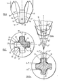
- Figure 1 is a side elevation of a driver for use in the present invention; Figure 1a is a view corresponding to Figure 1 with some angles exaggerated for the purposes of illustration, also showing the profile of a recess.
- Figure 2 is a plan view of a recess, showing a driver in cross section within the recess and Figure 2a is a corresponding view with some angles exaggerated;
- Figure 3 is an illustration of how one basic recess size can be used for a range of sizes of screw head; and
- Figure 4 is a section on line III-III of Figure 2;
- Figure 5 is a view corresponding to Figure 4 but using a recess of the same nominal size recessed more deeply into a larger screw head.
- The driver shown in Figure 1 is a conventional driver as has been sold for many years under the registered trade mark POZIDRIV with the exception that the nose of the driver has been shortened slightly. The driver has a shank 11 which terminates in a
nib 12 which is formed to engage in a cruciform recess. The shank 11 may be secured to a conventional screwdriver handle or the shank may be hexagonal for engagement in a driving head of a power driver. In the latter case the driver could perhaps be described strictly as a driver bit but throughout this specification and the claims any reference to a driver is intended to include such reference to a driver bit. - Reference should be made to the cross section of the driver shown in Figure 2 as well as to Figure 1 to understand the nature of the driver. The driver nib incorporates four
wings 13 which extend radially from a central core 14 at equally spaced angles around the core. Between each adjacent pair ofwings 13 there is arib 15 which is best seen in Figure 2 and which tends to strengthen the driver by increasing the dimensions of the central core and increasing the size of the roots of the wings. - The driver is used primarily for tightening screws with right hand threads and the
faces 16 of the wings which perform this driving function are known as driving faces. Theopposite face 17 of each wing is known as the back face. The driving faces 16 andback faces 17 of each wing are approximately parallel to each other and to aradial plane 18 through theaxis 19 of the driver and the centre of awing 13. However, there are slight but important deviations from this parallel relationship. Some angles in the drawings have been exaggerated to illustrate these tapers. As illustrated in Figure 1a, the drivingface 16 tapers in a downward direction towards theplane 18 at an angle of 0.1°. Thecorresponding back face 17 also has a downward and inward taper and in this case the angle is 1.70. As illustrated in Figure 2a, both the drivingface 16 andback face 17 taper in an outward direction towards theplane 18 at an angle of 1.3°. Also as illustrated in Figures 1 and 1a, the outer edge faces of thewings 13 taper in a downward direction. These outer faces lie on the surface of a cone which has a total included angle at its apex of 52°. - The recess shown primarily in Figure 2 but also in Figure 4 has four
radial grooves 21 radiating from acentral cavity 20 at equally spaced angles around the periphery of the recess.Valleys 22 are provided at the junctions of adjacent radial grooves and these provide space with a clearance for theribs 15 of the driver. The outer faces of thegrooves 21 are tapered in a downward and inward direction at a total included cone angle of 40° measured in the same way as the 52° angle of the driver. Although 40° has been chosen in this example, the feature of fundamental importance for the present invention is that the cone angle of the recess should not be more than the cone angle of the driver. It is preferable to use an angle in the range of 40° to 45° for the recess, that is substantially less than the cone angle of the driver. - Each
groove 21 has a drivenface 23 for engagement with a drivingface 16 of a driver, and aback face 24. As with the driving and back faces of the driver, the driven and back faces of the grooves of the recess are almost parallel with each other and with a central radial plane such as theplane 18. However, in a downward direction, the driven and back faces each taper inwardly at an angle of 1.7°. In plan, as illustrated clearly in Figure 2a, there is a reverse taper in the outward direction so that the outer edges of the grooves are wider than the inner edges of the grooves. The angle of this reverse taper is 0.2° on each face. - In accordance with the invention, the relative width of the grooves and the wings have to be such that the lower part of the driver is confined by and preferably wedges in the lower part of the recess. Once the basic angles of the faces have been selected, and a standard shortened POZIDRIV driver has been selected, it is a simple matter to select the appropriate width for a recess wing to just achieve wedging or a small clearance resulting in a confined fit at the correct depth of the driver in the recess.
- It is common practice to match one size of driver against a large number of screw heads which use the same nominal size of recess as the driver. For example, the most common size of driver is known as a Number 2 size driver and Number 2 size recesses are used in a range of different screws. With POZIDRIV and SUPADRIV, the only difference between one recess and another when both are of the same nominal size, has been the depth of penetration of a tapered punch with a standard shape and size of nose into the recess. This results in the lower end of all recesses of the same nominal size being identical, the total width and the groove width at the upper end of the recess depending on the depth of the recess. However, with the present invention, the depth of penetration of the driver into the recess which is determined by interengagement of the top outer edge of the grooves engaging with the outer conical faces of the wings, depends on the maximum diameter of the recess at its upper edge and thus on the depth of penetration of a punch into the head of the screw when forming the recess. This is best illustrated by reference to Figure 3. This shows the
outline 31 of the outer edges of the wings of a punch for forming the grooves in a recess intersected by two curved lines AB and CD. These lines AB and CD represent the top surface of two screw heads into which the punch has been driven to different depths. In relation to surface AB, the punch has produced a deep recess and this is wider at its upper edge than the width of the top of the recess represented by CD. Figure 4 illustrates the recess with top surface CD of Figure 3 engaged by the driver of Figure 1. Similarly Figure 5 represents the recess in surface AB of Figure 3 penetrated by the driver of Figure 1. It is clear from a comparison of Figures 4 and 5 that the driver penetrates nearer to the bottom of the recess of Figure 4 than that of Figure 5. - This difference in depth of penetration causes some difficulty in achieving a wedging action for all recesses because of the constant width at the base for the grooves chosen for a range of recesses. If the recess width is selected to produce the appropriate wedge fit in Figure 4, there is a small clearance in the arrangement of Figure 5 at the depth of penetration achieved. However, it has been found that in practice, it is possible to achieve a compromise groove width at the base of the groove which in practice allows complete insertion of the driver and provides for all depths of penetration of the punch an appropriate confined fit with only a small clearance, typically 0.02mm up to 0.05mm. This compromise is assisted by the fact that the effective angle of taper producing a wedging action is only 1.6°. This wedging angle can be derived from the difference between the total taper in a vertical direction on the wing, namely 1.7° plus 0.1° and the total taper of the groove, namely 1.7° plus 1.7°. With this shallow wedging angle, and bearing in mind some flexibility in the materials employed, the wedging action does not occur simply at one single depth but wedging can be achieved over a small range of depths compatible with some of the different depths of recess of the same nominal size.
- One further feature which assists in establishing wedging over a range of depths is that the wedging occurs only at the inner edges of the wings and grooves and not over the whole width of the wings or grooves. This can be seen from the fact that there is an effective taper in an outward direction between the wing and its groove amounting to 2.8°. This angle is the sum of the two 1.2° tapers on the wing and of the two reverse 0.2° tapers in each recess. Thus as the wedging takes place only at the inner edges of the wings and recesses, a smaller metal deformation is required to increase depth of penetration once wedging has been achieved and so to allow wedging over a range of depths than would be the case with full edge contact at the bottom of the wings.
- This edge contact at the inner ends only of the grooves and wings has the advantage that the wedging action does not produce an effective rotary driving connection between driver and recess at the bottom of the wing. This in turn allows the driver to twist through a small angle within the recess despite the wedging action until the outer edges of the driver come into contact with the upper outer edges of the sides of the grooves to produce point driving contact as described in greater detail in Patent No.1,521,141 and as is now common practice with the SUPADRIV recess.
- When a driver is used in mass production to drive a large number of identical screws of a size to achieve wedging action, the wedging surfaces at the nose of the driver may tend to wear during the first few driving operations to the correct dimensions to achieve effective full depth wedging. This wear does not affect the driving capability of the driver because driving torque is transmitted by the upper parts of the wings, remote from the area which achieves the wedging action.
- For the deeper and thus wider recesses for which a wedging action may not be achieved, the greater length of driver which penetrates into the recess and the greater recess width in themselves provide some stability. This stability is assisted by the fact that the nose of the driver still comes very close to being a wedge fit in the grooves and so is confined by the grooves to have very little free movement. This degree of confinement can be increased when torque is applied to the driver because the nose parts of the wings, as well as the upper parts of the wings become angled in the grooves and thereby have less freedom for lateral movement.
Claims (6)
Priority Applications (1)
| Application Number | Priority Date | Filing Date | Title |
|---|---|---|---|
| AT81303152T ATE19138T1 (en) | 1980-07-23 | 1981-07-10 | SCREW AND SCREWDRIVER COMBINATION. |
Applications Claiming Priority (2)
| Application Number | Priority Date | Filing Date | Title |
|---|---|---|---|
| GB8024144 | 1980-07-23 | ||
| GB8024144 | 1980-07-23 |
Publications (2)
| Publication Number | Publication Date |
|---|---|
| EP0046010A1 true EP0046010A1 (en) | 1982-02-17 |
| EP0046010B1 EP0046010B1 (en) | 1986-04-09 |
Family
ID=10514986
Family Applications (1)
| Application Number | Title | Priority Date | Filing Date |
|---|---|---|---|
| EP81303152A Expired EP0046010B1 (en) | 1980-07-23 | 1981-07-10 | Fastener and driver combination |
Country Status (16)
| Country | Link |
|---|---|
| US (1) | US4464957A (en) |
| EP (1) | EP0046010B1 (en) |
| JP (1) | JPS5771777A (en) |
| KR (1) | KR850000880B1 (en) |
| AT (1) | ATE19138T1 (en) |
| AU (1) | AU7286581A (en) |
| BR (1) | BR8104708A (en) |
| DE (1) | DE3174306D1 (en) |
| DK (1) | DK326081A (en) |
| ES (1) | ES268197Y (en) |
| HK (1) | HK80387A (en) |
| NO (1) | NO812513L (en) |
| PT (1) | PT73379B (en) |
| SG (1) | SG51487G (en) |
| ZA (1) | ZA814701B (en) |
| ZW (1) | ZW17481A1 (en) |
Cited By (1)
| Publication number | Priority date | Publication date | Assignee | Title |
|---|---|---|---|---|
| EP0369655A2 (en) * | 1988-11-14 | 1990-05-23 | Black & Decker Inc. | Improved screwdriver bit for Phillips-head fasteners |
Families Citing this family (22)
| Publication number | Priority date | Publication date | Assignee | Title |
|---|---|---|---|---|
| US4998454A (en) * | 1988-11-14 | 1991-03-12 | Black & Decker Inc. | Screwdriver bit for phillips-head fasteners |
| US4970922A (en) * | 1989-03-23 | 1990-11-20 | Snap-On Tools Corporation | Torque driving tool and retainer for driven member |
| WO1999047820A1 (en) * | 1998-03-18 | 1999-09-23 | Francisco Casino Lorite | Assembly of screw and screwdriver which are mutually self-gripping |
| JP3050542B1 (en) * | 1998-12-18 | 2000-06-12 | 有限会社新城製作所 | Screws with holed heads and their driver bits |
| US6199455B1 (en) * | 1999-03-08 | 2001-03-13 | Jjct Enterprises, Inc. | Driver, fastener and forming tool |
| US20030000351A1 (en) * | 2001-06-28 | 2003-01-02 | Ortho Development Corporation | Interference fit screw driver |
| SE526887C2 (en) * | 2003-10-01 | 2005-11-15 | Nobel Biocare Ab | Device for implants with internal mounting for turning tools |
| US6988432B2 (en) * | 2003-11-06 | 2006-01-24 | Uniscrew Worldwide, Inc. | Multi-tiered-recess screws |
| AU2010210491B2 (en) * | 2009-02-05 | 2013-10-24 | Milwaukee Electric Tool Corporation | Screwdriver |
| CA2702372C (en) * | 2009-04-28 | 2017-04-18 | Milwaukee Electric Tool Corporation | Multi-purpose tool |
| USD754513S1 (en) | 2010-02-05 | 2016-04-26 | Milwaukee Electric Tool Corporation | Screwdriver head |
| US8291795B2 (en) * | 2010-03-02 | 2012-10-23 | Phillips Screw Company | Fastener system with stable engagement and stick fit |
| CA2846336C (en) * | 2011-08-25 | 2021-02-23 | Infastech Intellectual Properties Pte. Ltd. | Tapered lobular driver and fastener |
| US20130047797A1 (en) * | 2011-08-25 | 2013-02-28 | Infastech Intellectual Properties Pte. Ltd. | Negative drive angle |
| US10968939B2 (en) * | 2011-08-25 | 2021-04-06 | Infastech Intellectual Properties Pte. Ltd. | Tapered lobular driver and fastener |
| US8955418B2 (en) | 2013-03-08 | 2015-02-17 | Black & Decker Inc. | Threaded fastener driving tool |
| TW201420284A (en) * | 2013-09-06 | 2014-06-01 | Great Metal Production Co Ltd E | Structure and manufacturing method for screwdriver driving portion |
| DE102013113401A1 (en) * | 2013-12-03 | 2015-06-03 | Adolf Würth GmbH & Co. KG | Screw and drive element with chamfer |
| KR102432730B1 (en) * | 2014-09-11 | 2022-08-12 | 인파스텍 인텔렉츄얼 프로퍼티즈 피티이. 엘티디. | Tapered lobular driver and fastener |
| EP3234382A1 (en) | 2014-12-17 | 2017-10-25 | Research Engineering & Manufacturing Inc. | Recessed head fastener and driver combination |
| CN111941336B (en) * | 2015-08-18 | 2022-07-08 | 英法斯泰克知识产权私人有限公司 | Tapered blade driver and fastener |
| SG11201811606XA (en) * | 2016-07-11 | 2019-01-30 | Phillips Screw Co | Fastener system with stabilizer rib |
Citations (6)
| Publication number | Priority date | Publication date | Assignee | Title |
|---|---|---|---|---|
| US2058197A (en) * | 1935-12-12 | 1936-10-20 | Maxwell A West | Screw |
| DE2451373A1 (en) * | 1973-10-29 | 1975-05-07 | Yamamoto Byora Co Ltd | FASTENING ELEMENT |
| DE2538139A1 (en) * | 1974-09-12 | 1976-03-25 | Phillips Screw Co | SCREW |
| DE2631941A1 (en) * | 1975-07-19 | 1977-02-03 | Gkn Fasteners Ltd | PHILLIPS SCREW, SCREWDRIVER AND EMBOSS STAMP FOR FORMING A PHOTO SLOT IN THE HEAD OF THE PHILLIPS SCREW |
| US4126908A (en) * | 1975-07-19 | 1978-11-28 | Gill Peter J | Threaded fastener recess forming punch |
| US4151621A (en) * | 1974-09-12 | 1979-05-01 | Phillips Screw Company | Tools for punching fastener heads |
Family Cites Families (7)
| Publication number | Priority date | Publication date | Assignee | Title |
|---|---|---|---|---|
| CA487293A (en) * | 1952-10-14 | J. Tomalis Joseph | Screw socket | |
| NL42923C (en) * | 1934-07-03 | |||
| GB715163A (en) * | 1952-05-06 | 1954-09-08 | Res Eng & Mfg | Driving tool for socket head fasteners |
| US2859782A (en) * | 1955-07-01 | 1958-11-11 | Phillips Screw Co | Hy-torque drive tool |
| US3575080A (en) * | 1968-12-02 | 1971-04-13 | Patrick M Hannay | Fastener wrenching means |
| US3658105A (en) * | 1970-05-04 | 1972-04-25 | John Burt | Fastener driving arrangement |
| US4228723A (en) * | 1977-09-16 | 1980-10-21 | Cunningham Hilary H | Fastener recess |
-
1981
- 1981-07-10 EP EP81303152A patent/EP0046010B1/en not_active Expired
- 1981-07-10 ZA ZA814701A patent/ZA814701B/en unknown
- 1981-07-10 AT AT81303152T patent/ATE19138T1/en not_active IP Right Cessation
- 1981-07-10 DE DE8181303152T patent/DE3174306D1/en not_active Expired
- 1981-07-14 US US06/283,343 patent/US4464957A/en not_active Expired - Lifetime
- 1981-07-14 AU AU72865/81A patent/AU7286581A/en not_active Abandoned
- 1981-07-16 PT PT73379A patent/PT73379B/en not_active IP Right Cessation
- 1981-07-21 KR KR1019810002643A patent/KR850000880B1/en active
- 1981-07-22 DK DK326081A patent/DK326081A/en not_active Application Discontinuation
- 1981-07-22 NO NO812513A patent/NO812513L/en unknown
- 1981-07-22 BR BR8104708A patent/BR8104708A/en unknown
- 1981-07-22 ES ES1981268197U patent/ES268197Y/en not_active Expired
- 1981-07-22 ZW ZW174/81A patent/ZW17481A1/en unknown
- 1981-07-23 JP JP56115830A patent/JPS5771777A/en active Pending
-
1987
- 1987-06-12 SG SG514/87A patent/SG51487G/en unknown
- 1987-10-29 HK HK803/87A patent/HK80387A/en unknown
Patent Citations (6)
| Publication number | Priority date | Publication date | Assignee | Title |
|---|---|---|---|---|
| US2058197A (en) * | 1935-12-12 | 1936-10-20 | Maxwell A West | Screw |
| DE2451373A1 (en) * | 1973-10-29 | 1975-05-07 | Yamamoto Byora Co Ltd | FASTENING ELEMENT |
| DE2538139A1 (en) * | 1974-09-12 | 1976-03-25 | Phillips Screw Co | SCREW |
| US4151621A (en) * | 1974-09-12 | 1979-05-01 | Phillips Screw Company | Tools for punching fastener heads |
| DE2631941A1 (en) * | 1975-07-19 | 1977-02-03 | Gkn Fasteners Ltd | PHILLIPS SCREW, SCREWDRIVER AND EMBOSS STAMP FOR FORMING A PHOTO SLOT IN THE HEAD OF THE PHILLIPS SCREW |
| US4126908A (en) * | 1975-07-19 | 1978-11-28 | Gill Peter J | Threaded fastener recess forming punch |
Cited By (2)
| Publication number | Priority date | Publication date | Assignee | Title |
|---|---|---|---|---|
| EP0369655A2 (en) * | 1988-11-14 | 1990-05-23 | Black & Decker Inc. | Improved screwdriver bit for Phillips-head fasteners |
| EP0369655A3 (en) * | 1988-11-14 | 1990-07-11 | Black & Decker Inc. | Improved screwdriver bit for phillips-head fasteners |
Also Published As
| Publication number | Publication date |
|---|---|
| ZW17481A1 (en) | 1981-12-02 |
| KR830005972A (en) | 1983-09-14 |
| NO812513L (en) | 1982-01-25 |
| ATE19138T1 (en) | 1986-04-15 |
| SG51487G (en) | 1987-08-28 |
| DK326081A (en) | 1982-01-24 |
| HK80387A (en) | 1987-11-06 |
| BR8104708A (en) | 1982-04-06 |
| KR850000880B1 (en) | 1985-06-26 |
| AU7286581A (en) | 1982-01-28 |
| US4464957A (en) | 1984-08-14 |
| PT73379A (en) | 1981-08-01 |
| ES268197Y (en) | 1983-12-01 |
| ES268197U (en) | 1983-06-01 |
| PT73379B (en) | 1982-10-01 |
| EP0046010B1 (en) | 1986-04-09 |
| JPS5771777A (en) | 1982-05-04 |
| DE3174306D1 (en) | 1986-05-15 |
| ZA814701B (en) | 1982-07-28 |
Similar Documents
| Publication | Publication Date | Title |
|---|---|---|
| EP0046010B1 (en) | Fastener and driver combination | |
| US4089357A (en) | Threaded fastener | |
| AU2021225170B2 (en) | Tapered lobular driver and fastener | |
| US3985170A (en) | Screwdriver | |
| US6186718B1 (en) | Threaded fastener having a head with a triangle centerpost within a triangle recess | |
| US6988432B2 (en) | Multi-tiered-recess screws | |
| US4339971A (en) | Fastener and driving tool | |
| US2800829A (en) | Cruciform recessed screw | |
| US3891017A (en) | Combination screw and screwdriver with axial guide spigot | |
| US5277531A (en) | Device having socket with retention surfaces | |
| EP1230489B2 (en) | System comprising a screw and a tool therefor | |
| CA2496108C (en) | 3-point/5-point fastener,3-point/5-point bit | |
| US4429599A (en) | One way screwdriver | |
| US4480514A (en) | Driving tool for tamper resistant screw | |
| US4579477A (en) | Pin-key assembly | |
| US2268515A (en) | Screw driver | |
| US20150000479A1 (en) | Tapered lobular driver and fastener | |
| US6453781B1 (en) | System for holding and tightening screws | |
| US5765980A (en) | Loosening preventive screw | |
| EP3191260B1 (en) | Tapered lobular driver and fastener | |
| US6397710B1 (en) | Screwdriver with slotted blades | |
| US4126908A (en) | Threaded fastener recess forming punch | |
| JP4148475B2 (en) | Cross hole screw | |
| WO2007131730A1 (en) | Screw or bolt with a recess in their head and driver for engaging the recess and method for producing the head | |
| RU217080U1 (en) | Fastener |
Legal Events
| Date | Code | Title | Description |
|---|---|---|---|
| PUAI | Public reference made under article 153(3) epc to a published international application that has entered the european phase |
Free format text: ORIGINAL CODE: 0009012 |
|
| AK | Designated contracting states |
Designated state(s): AT BE CH DE FR GB IT LI LU NL SE |
|
| 17P | Request for examination filed |
Effective date: 19820506 |
|
| RAP1 | Party data changed (applicant data changed or rights of an application transferred) |
Owner name: GKN SCREWS & FASTENERS LIMITED |
|
| GRAA | (expected) grant |
Free format text: ORIGINAL CODE: 0009210 |
|
| AK | Designated contracting states |
Kind code of ref document: B1 Designated state(s): AT BE CH DE FR GB IT LI LU NL SE |
|
| REF | Corresponds to: |
Ref document number: 19138 Country of ref document: AT Date of ref document: 19860415 Kind code of ref document: T |
|
| ITF | It: translation for a ep patent filed |
Owner name: JACOBACCI & PERANI S.P.A. |
|
| REF | Corresponds to: |
Ref document number: 3174306 Country of ref document: DE Date of ref document: 19860515 |
|
| RAP2 | Party data changed (patent owner data changed or rights of a patent transferred) |
Owner name: EUROPEAN INDUSTRIAL SERVICES (FASTENERS) LIMITED |
|
| ET | Fr: translation filed | ||
| NLXE | Nl: other communications concerning ep-patents (part 3 heading xe) |
Free format text: IN PAT.BUL.18/86,PAGES 2231 AND 2248 SHOULD BE MODIFIED INTO:EUROPEAN INDUSTRIAL SERVICES (FASTENERS) LIMITED |
|
| BECN | Be: change of holder's name |
Effective date: 19860409 |
|
| PLBE | No opposition filed within time limit |
Free format text: ORIGINAL CODE: 0009261 |
|
| STAA | Information on the status of an ep patent application or granted ep patent |
Free format text: STATUS: NO OPPOSITION FILED WITHIN TIME LIMIT |
|
| 26N | No opposition filed | ||
| ITTA | It: last paid annual fee | ||
| PGFP | Annual fee paid to national office [announced via postgrant information from national office to epo] |
Ref country code: GB Payment date: 19920626 Year of fee payment: 12 |
|
| PGFP | Annual fee paid to national office [announced via postgrant information from national office to epo] |
Ref country code: FR Payment date: 19920707 Year of fee payment: 12 |
|
| PGFP | Annual fee paid to national office [announced via postgrant information from national office to epo] |
Ref country code: CH Payment date: 19920709 Year of fee payment: 12 |
|
| PGFP | Annual fee paid to national office [announced via postgrant information from national office to epo] |
Ref country code: SE Payment date: 19920713 Year of fee payment: 12 |
|
| PGFP | Annual fee paid to national office [announced via postgrant information from national office to epo] |
Ref country code: AT Payment date: 19920714 Year of fee payment: 12 |
|
| PGFP | Annual fee paid to national office [announced via postgrant information from national office to epo] |
Ref country code: DE Payment date: 19920727 Year of fee payment: 12 |
|
| PGFP | Annual fee paid to national office [announced via postgrant information from national office to epo] |
Ref country code: NL Payment date: 19920731 Year of fee payment: 12 |
|
| PGFP | Annual fee paid to national office [announced via postgrant information from national office to epo] |
Ref country code: LU Payment date: 19920811 Year of fee payment: 12 |
|
| PGFP | Annual fee paid to national office [announced via postgrant information from national office to epo] |
Ref country code: BE Payment date: 19920831 Year of fee payment: 12 |
|
| EPTA | Lu: last paid annual fee | ||
| PG25 | Lapsed in a contracting state [announced via postgrant information from national office to epo] |
Ref country code: LU Free format text: LAPSE BECAUSE OF NON-PAYMENT OF DUE FEES Effective date: 19930710 Ref country code: GB Effective date: 19930710 Ref country code: AT Effective date: 19930710 |
|
| PG25 | Lapsed in a contracting state [announced via postgrant information from national office to epo] |
Ref country code: SE Effective date: 19930711 |
|
| PG25 | Lapsed in a contracting state [announced via postgrant information from national office to epo] |
Ref country code: LI Effective date: 19930731 Ref country code: CH Effective date: 19930731 Ref country code: BE Effective date: 19930731 |
|
| BERE | Be: lapsed |
Owner name: EUROPEAN INDUSTRIAL SERVICES (FASTENERS) LTD Effective date: 19930731 |
|
| PG25 | Lapsed in a contracting state [announced via postgrant information from national office to epo] |
Ref country code: NL Effective date: 19940201 |
|
| GBPC | Gb: european patent ceased through non-payment of renewal fee |
Effective date: 19930710 |
|
| NLV4 | Nl: lapsed or anulled due to non-payment of the annual fee | ||
| PG25 | Lapsed in a contracting state [announced via postgrant information from national office to epo] |
Ref country code: FR Effective date: 19940331 |
|
| REG | Reference to a national code |
Ref country code: CH Ref legal event code: PL |
|
| PG25 | Lapsed in a contracting state [announced via postgrant information from national office to epo] |
Ref country code: DE Effective date: 19940401 |
|
| REG | Reference to a national code |
Ref country code: FR Ref legal event code: ST |
|
| EUG | Se: european patent has lapsed |
Ref document number: 81303152.3 Effective date: 19940210 |